Work2 House part2 - rising edge
I am trying to modify the code to use a rising edge, but if I do it just doesn't quite work. Set a breakpoint on the earpiece never hits so it's as if the trigger is never pulled.
Also when it does not work I tried a TRIGGER_HIGH_LEVEL. He crashed to the virtual machine.
Hmmm... You use the GPIOSwitchTest project?
It worked by using TRIGGER_BOTH_EDGES?
If so, first change the code for the following valueChanged method:
    public void valueChanged(PinEvent event) {
        GPIOPin pin = (GPIOPin) event.getPeripheral();

            if (pin == switchPin) {
                if (event.getValue() == true) {
                        System.out.println(" true");
                } else {
                        System.out.println(" false");
                }

            }
    }
So if you change the GPIOPinConfig to TRIGGER_BOTH_EDGES to TRIGGER_RISING_EDGE, you will see that real messages. See this post to explain why the change of the code is necessary.
As to why TRIGGER_HIGH_LEVEL "crash the virtual machine" - I think what you meant was, he threw an exception - specifically and IllegalArgumentException.
I'll add this as a note, but in the documentation of the Raspberry Pi in the GPIO section, it says: "the triggering modes TRIGGER_HIGH_LEVEL , TRIGGER_LOW_LEVEL , and TRIGGER_BOTH_LEVELS are not supported on the Raspberry Pi.»
Tom
Tags: Java
Similar Questions
-
Operating system: Windows XP
Hardware: PCI 6259
Terminals used: PFI0 and PFI2
Counters used: Ctr0 and Ctr1
IM developing an application for the acquisition of data where timed loop synchronization source comes from my PFI2 (using the string A of an encoder). IM basically trying to acquire data based on the number of ticks from my encoder. For the synchronization source, I use counter 1 to capture the rising edge and have the loop time-acquisition of data. At the same time, Im using the counter 0 to count the number of rising edges so I know exactly in what tick data was acquired. PFI0 and PFI2 are connect to channel A of the encoder.
Questions:
Timed loop acquires data at each tick, because when I discover the data (text) file is missing count of my encoder value. Is it because there is a limitation on the Windows operating system? I used a noculars to measure the frequency at the maximum rotation of the channel encoder and 6,757 kHz. All solutions?
Also, is there anyway I can route the source channel internally an encoder to generate synchronization source instead of using another counter? I have attached my VI.
Hello
All the samples that you acquire will be read by LabVIEW in a sequential manner. Figure 4-21 on the M-series on page 80 (4-34) shows that you will acquire all the samples you request all channels that you enjoy in sequentially.
-
Hello
I use a PXI-6251 data acquisition card.
On this one, I trigger a final signal on analog output.
I would like to launch a rising edge on the terminal where the analog output task is really run.
Actually I provoq a trigger output when the analog task is to start.
Is this possible?
Thanks for the reply.
Concerning
=========================
Hello
I has a PXI-6251
On this one I generated the United Nations end analog signal.
I wish every a rising edge on a PFIX output when the build task to start. Only then this output falls to 0 when the task is stopped...
Possible is it?
Thanks for your replies.
Hello __KB__,
I think you should start from this example: https://decibel.ni.com/content/docs/DOC-5374
Then, you have to adapt in order to define a model that generates a high level as soon as starts the analog task and which generates a low level at the end of the acquisition of finishes.
In order to know which digital line corresponds with your PFI line, you will need to look at the documentation of the PXI-6251 (http://www.ni.com/pdf/manuals/371291h.pdf, page 14). You can also get information from MAX.
Kind regards
-
6602: rising edge capture hardware interruption
I have this input signal:
I have to do something about rising as soon as possible.
My idea is to receive a break hw of the Board of Directors and write a Sri soubroutine.
I read about the callback function, so I write code.
But when I call:
DAQmxErrChk (DAQmxCfgChangeDetectionTiming (udpTaskHandle,
Dev1/Ctr0"."
Dev1/Ctr0"."
DAQmx_Val_ContSamps,
1)) ;I have an error for the ctr0, it seems that I can use the port0 onli.
Now... is my question on port0 a thread of software that continually read the value of the pins?
Or is it still a material interruption?
I think a software thread has a large latency for me, at this point useless 6602 jury,
I could read the signal on LPT port standard.
Thanks for the reply.
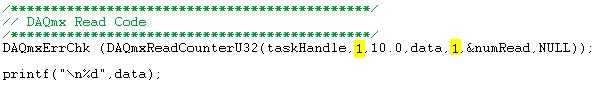
If you do not want to read the value of the counter, try replacing the code read what follows:
You currently ask 1000 samples to read so the Read function is blocked until 1000 samples are available. Reading is not necessary if all you want to do is raise the event to do something else (which is what it sounded like messages earlier).
Let me know how it goes!
Best regards
-
County rising edge specifier "10280" generates the error "-200220"»
Hello
I use the box USB-6008 with PFI 0 configured as a counter edge. Everything works fine when I use it to count the edges fall with the "10171" specifier, but .vi DAQmxBase Create Channel (CI-County edges) generates the above error if I simply replaces "10171" with "10280. This specifier is not recognized by the device?
Thank you
Tyler
Hey Tyler,
I've dug into this and found an internal report, and apparently only a falling edge can be used as a trigger of edge with patches of meter. The other problem is that, even if you can use both, there is that a single input pin for this meter and edge only one type can be detected at the time. The only solution I see would be to try to find a device with several counters, or take an another 6008 and use it to count the edges of the second switch.
-
Hello, I am designing a detector of negative edge using a d-type flip flop that gets a signal from two cascaded from the binary counters that are used to reset when the desired value is reached. The design should include a frequency of window, but I do not know how to implement it. I tried to implement but I could, but I don't know if it works. No idea?
Hello, thanks for the answer
Sorry, but I guess I'm not smart enough to digest your description.
I have-
We must build counter for 0.51 with reset - you did.
We must build flipflop (FF) with triggers on falling edge.
the possible solutions are-
-You can use rising edge FF if you could reverse the trigger signal.
Learn about the different types of FF, some of them work on edges falling
with it will be useful
Good luckMichael
-
Single channel match trigger speed model vs onset of edge on the PXI-6562
I think that my question boils down to this: what function does the edge of trigger plan that is not provided by the model match trigger?
As far as I know, the only differnece on the PXI-6562 is the edge trigger has its own pins dedicated (PFI pins and pins RSTI) to detect a trigger, while the model match trigger detects a rising edge or falling on a regular input pin.
Is there a difference in performance (for example, the time to rearm)?
Are both triggers synchronous types with the sample for dynamic acquisition clock?
On my application:
I acquire a signal off a SPI bus, triggering the CS line. I start to acquire data when the CS line going down and stops when the CS line is high. As I acquire data CS on a regular supply, it seems logical trigger on a pattern for this channel only match. I'm curious to know if there is any advantage to connect a PFI PIN to my CS of entry so that I can start using digital edge type.
Thanks in advance,
Arthur
Arthur,
There is no difference with regard to performance using a digital camera compared to a type of pattern match trigger. Specifications for rearm time reference to the trigger type (Start, reference, etc.) in the samples to rearm, and there is no difference with the performance when you use a digital advantage over a line/PFI line Trigger and a correspondence to the model used on the input signal. Change the source of the trigger itself will not change the performance of the material that occurs after the trigger is received. This behavior to sync with the clocks of acquisition regardless of the input source. We're just looking at different sources for the jury to look for a given trigger.
-
Digital output on two fronts and internal clock edge
Hola,
I use a PCIe-6537 and LabView 8.6 unit. This unit has an internal clock up to 50 MHz. I am trying to output a digital square wave at the maximum rate of 50 MHz I put my 50 MHz clock frequency, build my table of 1 and 0, convert it and the digital waveforms (on port0/$line0 if it makes a difference) output. During playback of the wave on a scope it shows a [very] good, but only 25 MHz square wave. The reason for which I believe is being only a sample of output (1 or 0) DAQ card for each rising edge of the clock and not fall. This is why the output wave will always be twice as slow as the clock frequency. Is there a way to power on the edge both amounts and descendants of the sample clock so that I can get a square of 50 MHz, wave or should I try a different technique?
I'm all ears...
~ JS
ISO
The ability to generate/acquire both the rising and falling clock edge is called double rate (DDR). We have an application on the use of DDR note with our instruments.
Of the advanced features of digital devices: Double data rate
The Board you use, however, is not capable of a double speed. The only devices capable of DDR at the moment are the NI 6561 and NI 6562, which were maps LVDS. You can get out on the forehead or the edge down, not both. You can use an external circuit to generate a signal of 50 Mbps. Basically, would need you an XOR gate and combine two different ways to create a signal 50 Mbit/s on a 50 MHz clock frequency.
Here is an example of how you can achieve. The white paper I mentioned above will guide you in this process.
On the other hand, we have boards of 100 MHz that will give you a square of 50 MHz, similar to the desired wave. The NI 6542, 6552, 6544 and 6545 are all 100 MHz or higher. The SMU-6545 is a 200 MHz Board. You can use one of these tips to generate higher frequency signals.
Hope that helps. I would like to know your opinion on this.
-
Measure the time of the rising edges of a digital stream using a USB-6341
I have a DAQ USB-6341 map.
I use Measurement Studio (writing code in c#) on a Windows 7 computer.
I'm relatively new to the DAQ cards, programming, so I could ask something that is obvious (sorry if this is the case).
I went out a stream of digital pulses to an analog output channel. I wired this channel to one input of the meter channel. I am able to measure the number of edges upward to the inlet of the meter channel (since the digial flow is continuous, the number of rising edges increases with time).
I would like a time stamp of each rising transition and I like to keep these timestamps in a table without ever growing (or maybe bin these timestamps in a histogram).
Set up the meter channel to provide the timestamp data? (rather than just count)
Thank you for your help.
WRB,
The meter must be able to measure the relative time between the different edges of your signal. To do this, you will take care to set the meter to measure time. It will measure how long a full period of your signal takes. You can configure edge that you want to start with. You'll want to set up your timed 'implied' measure. This sets up the meter to automatically take action whenever a period is over. While it's not exactly a timestamp, you can find the distance between two edges by adding the time periods between the banks in question.
I see another technique that you can use. This would put the counter to edges of County one of the basics of time of your device (it has 100 KHz, 20 MHz and 100 MHz bases long). Then configure the task to use your signal as a sample (configuration to use rising edge) clock. Whenever the song occurs, you will get the number of ticks ticks selected timebase that took place at that time. One thing to note here, however, is that the counters are 32-bit wide, so your code will have to manage the overthrow of this charge if you are using a fast time and base running for long periods of time.
Hope that helps,
Dan
-
PCI6120-acquire an analogue signal on each edge of a digital signal
Hello
I have the card PCI-6120 and Labview 7.1.
I have a digital signal of the encoder. Am interested in buying an analog voltage on each rising edge of the digital signal. In addition, I have another digital signal (index) between which I wish to make the acquisition.
I tried several options. But I can't get on the digital dashboard via the hardware. Please help urgently. Alternative, I migrated to the acquisitions acquisition high speed analog and two digital channels and deteting change in software programming and then find the analog voltage. Which is heavy and inefficient.
Kindly guide correct programming technique.
Concerning
Marie-Hélène
Hi, Maud.
Thanks for the update and I hope that your well today.
Sorry for the delay but it was the Easter holidays!
Thank you for your congratulations.
I put your sampling frequency at the maximum rate of the clock source (encoder). The DAQmx driver uses the sampling frequency (and the number of samples per channel) information to perform various calculations and set sizes for the buffer.
If you set it too high, nothing will happen-guests still just on each edge of the unit receive. If you set it too low, your stamp could be too small and you may lose data.
Hope this helps,
-
F-> T amounting to edge detection
Hello
I am trying to understand any way or somethink, which detects the rising edge and the output value will be true (when the state changes from 0 to 1).
So if the entry is 0, output is set to false. When the input is 1, output is set to false. Just the moment between 0 and 1 must be true to the exit.
Are you all plese advice?

Thank you, pelda
Feedback node, and superior service.
Or Boolean intersection Pt by Pt.

-
Using ChangeDetectionEvent with the NI USB-6259 housing
Hello
I am very new to labview and LabWindows, so maybe it's very trivial to solve.
I would like to perform an action (change some elements of the user interface) whenever I get a rising edge of a TTL signal.
I hoped to achieve by following the example of ReadDigChan-ChangeDetectionEvent, and by defining a DAQmxRegisterSignalEvent() front on one of the digital input lines, but I can't even use the example for my
USB-6259 (BNC).
When I try to perform detection of changes on the lines from the port 1 and 2 I get
Modalities indicated do not support change detection. Select the lines that support the detection of changes. Device: Dev1 physical Channel: port1/$line0 the task name: _unnamedTask<0> Code of State :-201020
I missunderstand something? Should the digital in ports on the detection of change of 6259 support?
When you try the same thing with port0 the application hangs for a long time and threw just a message saying that
DAQmxReadDigitalLines() timedout.
I hope this is enough information to answer the question. If not, what else do you need?
Thank you
Manual
Hello
It seems that the USB-6259 does not support the detection of changes.
Link:
In NOR-DAQmx digital change detection
-
has triggered the numerical sequence of read/write
Hello
I'm pretty sure it's impossible to do in Labview, but thought I would ask the question just in case:
On a digital falling edge I need to define a digital line on a highest PCI-6224 and a low, then read sixteen lines as a port. Output high and low lines should change status then and sixteen lines should be read again.
The process is repeated on the edges of successive falls. The time between edges may be as short as 11 microseconds (90kHz).
We have currently a program written in C++ to do this job, but I want to create something a little more friendly and have virtually no C++ experience myself.
Thank you.
Hi Simon,.
I have an idea how to do that using the DAQmx card. This has not been tested, but I think it should work with just a few tricks with DAQmx. There are three tasks that will be required:
Meter output
==============This should be a task redeclenchables meter. Take a look at the example in the example finder LabVIEW under Hardware Input/Ouput > DAQmx > generating digital pulses > Gen dig Pulse Train-finishes-redeclenchables.
1. This should generate two pulse whenever the external trigger is received so your 11us impulses are the trigger for this task.
2. these impulses are then for each reading of digital lines:Rising edge - changed lines to enable
Falling edge - read data.By making these large enough pulse (> 140ns) that will take care of the running lines.
3. the gap between pulses must be long enough for any delay required between the readings.
Digital output
==============It must be a regenerative continuous power - see example material entry and exit > DAQmx > digital generation > Cont writing Dig Ext Clock.vi - Port.
1. the clock source should be set by right-clicking on the source control. Select i/o filtering name and then check the box advanced terminals. You can then select him appropriates the in-house production of counters.
2. you need to set the clock for the front edge.
3. the entrepreneurs that the buffer with two outputs that we require for example 10 and 01 and then sending a pulse to the clock pass effectively between the two.
Digital input
=============This should be a task of standard continuous input as in the example of the input and output material > DAQmx > digital measures > Cont read Dig channel-Ext Clk.vi
1. set up the VI of timing almost identical to the output task. Same source, but this time on the front clock down.
2 do with the data you want!
Overall program
===============The main consideration is that you should start the meter output last as soon as it runs other can start synchronization of data.
I hope this helps and is clear enough. I would like to know if it makes sense or if you would like more information or even no matter what assistance this program construction.
Kind regards
-
How can I use two counters to capture a pulse ttl for a specified time
Configuration: Card counting 6062 PCI w / BNC 2121 Board running under LV 9.0 PerkinElmer Avanlance Photodiode (SPCM-AQRH-13)
I searched through the forums and fell on the theme of framing an image while collecting signals from a source for a specified time.
The example in terms of falkpl in 2005:
"
Dismal Hello,
I'll try to point you in the right
direction to start coding the application, but do not forget my
suggestions have to be modified to your specific request.For
the task output redeclenchables finished meter you need to
your counter seconds in this application, I suggest to take a look
in the Finder example in LabVIEW ('Help' are examples) and less
DAQmx hardware entry & exit"" generating digital impulses. Here,
you will find some Gen dig Pulse - Retriggerable.vi. You can use this for
Create your door 4 pulses ms it's over (not a pulse train) and
redeclenchables (for each time you go to the next step.In
regards to the configuration of the first counter, there are several things to
consider, and I can offer initial help to get set up. You
in-house allows to route internal CTR1 (4ms of pulse) output for your CTR0
Door to measure only during the time. Here are additional
Info to do this in LabVIEW. The source of your task of edges ABOVE County
will be the TTL signal you are measuring and counting. It comes
on the PFI line that corresponds with CTR0 Source.When
you make a measurement finished with CTR0, you will take only heads while
the door is high and your source has a rising edge. You can set the
measure over to start on a trigger, which is not clear in this
for example, that you have identified. Since you know that you have a finished 4ms pulse
time to measure, you can set the duration of your measure
as a result.I found this
Forum which may help some, but the coding is
textual. I hope this can give you a good starting point for
programming. -
PXI SFP 5105 configured Vs Acquisition VI
Hello
I recently started to use the NI PXI-5105 cards, I need to capture (noise level<20KHz) on="" top="" of="" my="" dc="" signal,="" i="" used="" software="" front="" panel="" to="" capture rising="" edge="" of="" an="" analog="" signal i="" was="" able="" to="" capture="" signal="" when="" it="" meets="" my="" trigger="" requirements="" same="" as="" configured="" acguisition="" example="" vi="" also="" vi="" recommended="" input="" signal freq="" ="" is="" 100khz,="" what="" changes="" i="" need="" to="" do="" in="" order="" to="" make="" this="" vi="" to="" trigger="" when="" the="" noise="" level="" on="" my="" dc="" signal="" exceeds="" certain="" point="" can="" anyone="" please="" help="" me="" with="" this="">
Thanks in advance!
Hey djo.
If I understand your description, the best sounds of relaxation as it can be a trigger of hysteresis with coupling AC trigger in order to eliminate the effects of your DC signal. You will then be able to adjust the amplitude of the noise that you are looking for as the level to which you want to trigger off. You can find information about the options available with the help of scanners trigger high speed OR under Fundamentals > trigger.

Maybe you are looking for
-
Equium U400-145, recover data from HARD drive
Hi all My Toshiba Equium U400-145 is eventually died after a number of evidence of years of hard work! I bought a disc docking sata hard and recovered a number of data on my new computer.The problem is that it is only about half of the data, and espe
-
It is an Acer Aspire 5315 that my mom gave to my daughter. She says that she has never created a system restore point that requires a password so how to do this? Oh, and I have no disc as it came preloaded.
-
Hard Drive C full disk cleanup does not
My hard drive C has been fine for a long time. Then all of a sudden in a period of about a year he started fill by itself. I would deal with the problem with the disk cleaning and remove programs and files is no longer needed, but every time I did
-
I have windows 7 Professional to the high grade
I put windows 7 professional for my computer windows 7 I also got at best buy on the same day. I tried to install the top grade, but I get a message saying invaled product key, I have 30 days to valadate the product key code why? All the numbers and
-
Impossible to compile Adobe AIR for Android TV
HelloWe try to compile the AIR with the flags are:< android >< manifestAdditions > <! [CDATA]< manifest android: installLocation = "auto" >...< / manifesto >[]] > < / manifestAdditions >< supportsAndroidTV > true < / supportsAndroidTV >< banner > "pa