Rising edge on AO Start
Hello
I use a PXI-6251 data acquisition card.
On this one, I trigger a final signal on analog output.
I would like to launch a rising edge on the terminal where the analog output task is really run.
Actually I provoq a trigger output when the analog task is to start.
Is this possible?
Thanks for the reply.
Concerning
=========================
Hello
I has a PXI-6251
On this one I generated the United Nations end analog signal.
I wish every a rising edge on a PFIX output when the build task to start. Only then this output falls to 0 when the task is stopped...
Possible is it?
Thanks for your replies.
Hello __KB__,
I think you should start from this example: https://decibel.ni.com/content/docs/DOC-5374
Then, you have to adapt in order to define a model that generates a high level as soon as starts the analog task and which generates a low level at the end of the acquisition of finishes.
In order to know which digital line corresponds with your PFI line, you will need to look at the documentation of the PXI-6251 (http://www.ni.com/pdf/manuals/371291h.pdf, page 14). You can also get information from MAX.
Kind regards
Tags: NI Software
Similar Questions
-
Operating system: Windows XP
Hardware: PCI 6259
Terminals used: PFI0 and PFI2
Counters used: Ctr0 and Ctr1
IM developing an application for the acquisition of data where timed loop synchronization source comes from my PFI2 (using the string A of an encoder). IM basically trying to acquire data based on the number of ticks from my encoder. For the synchronization source, I use counter 1 to capture the rising edge and have the loop time-acquisition of data. At the same time, Im using the counter 0 to count the number of rising edges so I know exactly in what tick data was acquired. PFI0 and PFI2 are connect to channel A of the encoder.
Questions:
Timed loop acquires data at each tick, because when I discover the data (text) file is missing count of my encoder value. Is it because there is a limitation on the Windows operating system? I used a noculars to measure the frequency at the maximum rotation of the channel encoder and 6,757 kHz. All solutions?
Also, is there anyway I can route the source channel internally an encoder to generate synchronization source instead of using another counter? I have attached my VI.
Hello
All the samples that you acquire will be read by LabVIEW in a sequential manner. Figure 4-21 on the M-series on page 80 (4-34) shows that you will acquire all the samples you request all channels that you enjoy in sequentially.
-
Work2 House part2 - rising edge
I am trying to modify the code to use a rising edge, but if I do it just doesn't quite work. Set a breakpoint on the earpiece never hits so it's as if the trigger is never pulled.
Also when it does not work I tried a TRIGGER_HIGH_LEVEL. He crashed to the virtual machine.
Hmmm... You use the GPIOSwitchTest project?
It worked by using TRIGGER_BOTH_EDGES?
If so, first change the code for the following valueChanged method:
    public void valueChanged(PinEvent event) {
        GPIOPin pin = (GPIOPin) event.getPeripheral();

            if (pin == switchPin) {
                if (event.getValue() == true) {
                        System.out.println(" true");
                } else {
                        System.out.println(" false");
                }

            }
    }
So if you change the GPIOPinConfig to TRIGGER_BOTH_EDGES to TRIGGER_RISING_EDGE, you will see that real messages. See this post to explain why the change of the code is necessary.
As to why TRIGGER_HIGH_LEVEL "crash the virtual machine" - I think what you meant was, he threw an exception - specifically and IllegalArgumentException.
I'll add this as a note, but in the documentation of the Raspberry Pi in the GPIO section, it says: "the triggering modes
TRIGGER_HIGH_LEVEL,TRIGGER_LOW_LEVEL, andTRIGGER_BOTH_LEVELSare not supported on the Raspberry Pi.»Tom
-
6602: rising edge capture hardware interruption
I have this input signal:
I have to do something about rising as soon as possible.
My idea is to receive a break hw of the Board of Directors and write a Sri soubroutine.
I read about the callback function, so I write code.
But when I call:
DAQmxErrChk (DAQmxCfgChangeDetectionTiming (udpTaskHandle,
Dev1/Ctr0"."
Dev1/Ctr0"."
DAQmx_Val_ContSamps,
1)) ;I have an error for the ctr0, it seems that I can use the port0 onli.
Now... is my question on port0 a thread of software that continually read the value of the pins?
Or is it still a material interruption?
I think a software thread has a large latency for me, at this point useless 6602 jury,
I could read the signal on LPT port standard.
Thanks for the reply.
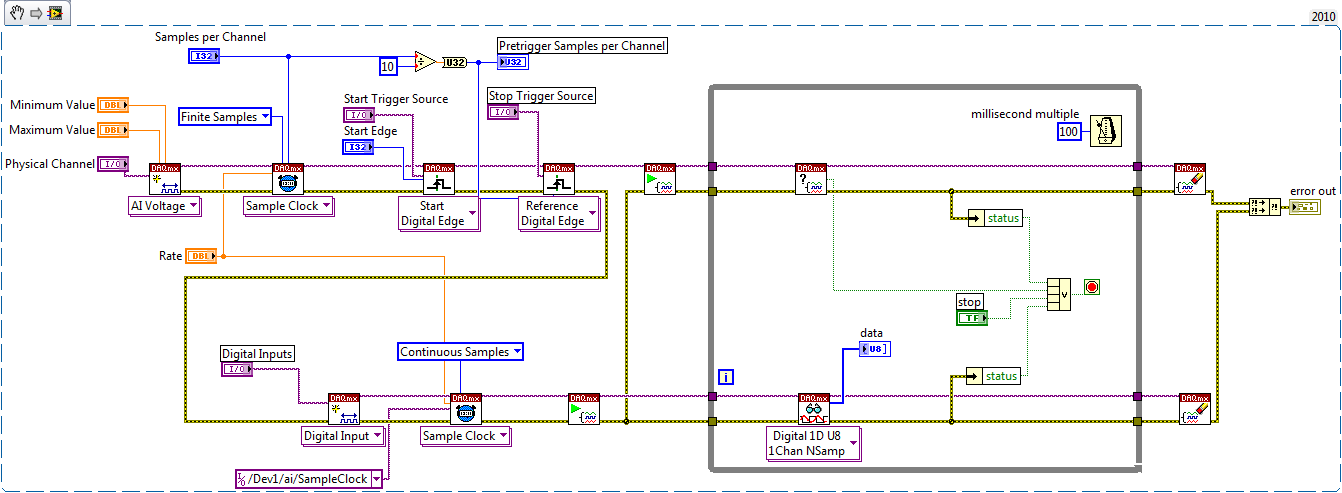
If you do not want to read the value of the counter, try replacing the code read what follows:
You currently ask 1000 samples to read so the Read function is blocked until 1000 samples are available. Reading is not necessary if all you want to do is raise the event to do something else (which is what it sounded like messages earlier).
Let me know how it goes!
Best regards
-
County rising edge specifier "10280" generates the error "-200220"»
Hello
I use the box USB-6008 with PFI 0 configured as a counter edge. Everything works fine when I use it to count the edges fall with the "10171" specifier, but .vi DAQmxBase Create Channel (CI-County edges) generates the above error if I simply replaces "10171" with "10280. This specifier is not recognized by the device?
Thank you
Tyler
Hey Tyler,
I've dug into this and found an internal report, and apparently only a falling edge can be used as a trigger of edge with patches of meter. The other problem is that, even if you can use both, there is that a single input pin for this meter and edge only one type can be detected at the time. The only solution I see would be to try to find a device with several counters, or take an another 6008 and use it to count the edges of the second switch.
-
Animation animate edge does not start the first time I load the page. But the second time.
Hi all
I have problems with animation of edge on a web page. It does not load the first time the page is loaded, but charge very well the second time or at any time after that. To test I empty my cache, then reload the page. It seams to work in Internet Explorer, the first time, but not Firefox or chrome.
I have a temporary copy of the page here... http://emiwip.com/Monique-Mathieu/landing-page-WIP.html
Can someone tell me what is happening?
Thank you.
Dan
I found the answer here... Publication is no longer works in the latest edge
It seems that you need to load the last jQuery in the head of the pag. That suits him.
Dan
-
Edge animate not starting corectly 8.1 Win
It comes to the screen on startup of edge animate after that I tried to set the stage size that initially appear without all dimensions!

Sometimes I get only the following:

I have re-installed and the same thing happens. I install this through the Adobe Creative Cloud application. I have other Adobe products installed in the same way and have had no other problems.
Any ideas what can cause this behavior?
I completely uninstalled the ESET Smart Security and restarted Windows.
Adobe Edge animate now works correctly, so he seems to have been a conflict with ESET.
NOTE: I have re-installed ESET Smart Security and Adobe Edge animate still works! It must have been a parameter in the old installation that was causing a problem.
-
Can I get an animation of edge for automatic start without user intervention?
I have an animation loop edge that I placed in my DPS document. In the overlays of Folio I have Auto Play checked with a delay deuxieme.125 and transparent background. When I saw it if the animation begins after that I have the touch. I looked at this thread and there was some talk about possibly adding code to the animation of the edge? Is there another way? Thank you!
Thanks, I finally recreate the design from scratch and it works now. I don't have a chance to test in the browser but. I appreciate the help!
-
How to synchronize the start of IT and relaxation the Scan list (DAQmx Switch)
Hello
I want to measure samples of N to the AI0 of Council NI PXI 4461. The measurement starts on a rising edge of a digital triggering provided to the PFI0 of the same Board. The measure is configured with samples of N/2 pretrigged. So far, everything is under control...
Using an NI PXI 2567 Board, the signal applied at the entrance the 4461 (AI0) switches between a V2 and V1 signal. I would like to synchronize the switch between the two signals with the trigger signal applied to the input of the PFI0 Governing Council 4461. In order to obtain samples of N/2 of V1 and V2 samples N/2. Synchronization of 1 to 5 ms would suffice!
My question is how to synchronize the start of acquisition of AI pretrigged of 4461 with the switch control given by the Council of 2567?
Thank you in advance for your help...
PS: the configuration of the system is:
-LabView 8.5
-Chassis PXI-1044
PXI-4461 on slot 2
Module 4-slot PXI-2567
Hi Frederic,.
I came back to this recently and used the following examples to run the desired synchronization.
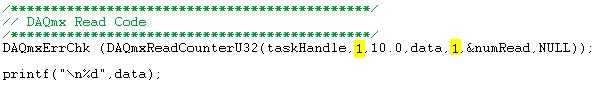
PXI-4461: Acq & graph tension-Int Clk - dig Start & Ref .vi
Samples per channel = 1000
Rate (Hz) = 10000.00
Start the trigger Source = / [name of the instrument DAQmx] / PXI_Trig0
Onboard start = fall
Reference Source Trigger = DAQmx Device Name] / PXI_Trig0
Reference edge = fall
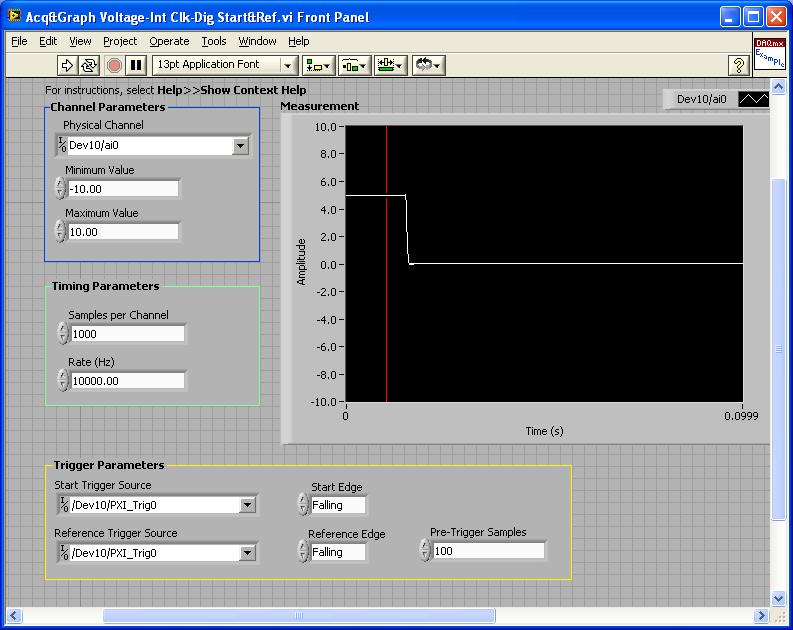
Trigger samples = Variable (100, 500, 900)
PXI-2567: Switch Scaning-SW Trigger.vi
Advance the output terminal full = / [name of the instrument DAQmx] / PXI_Trig0
Scan list = / [name of the instrument DAQmx] / ch0-> com0.
Scan list = / [name of the instrument DAQmx] / ch1-> com1;
Hardware configuration:
The PXI-2567 module controls an external relay that switches between the voltage of 5 V on ch0 and ch1 0 V.
The PXI-4461 connects to the COM of the external relay and therefore reads 5V when ch0 is connected; 0 v when ch1 is connected.
Procedure: The above examples are used in the following procedure.
1. run the PXI-4461 VI. A start trigger (falling edge) is necessary to start collecting samples before firing.
2. launch the module, PXI - 2567 VI. When ch0 is initially (and immediately) on com0, a trigger is sent to PXI_Trig0. The PXI-4461 will begin to acquire samples before firing.
3. - click on the "Connect to the next" button on the front of the PXI - 2567 VI module. This sends a trigger to entry software for the PXI-2567 module and the transitions of the scan for ch1-> com1 list. Once the PXI-2567 module remains (debounced), advanced complete relaxation is sent on PXI_Trig0 for the PXI-4461. The PXI-4461 will begin to acquire samples after outbreak.
Note: Instead of the trigger of the software entry, an external input trigger can be used (e.g. PXI_Trig1).
Results:
> Before instant release of samples = 100
Delay is caused by the time of actuation of external relay.
> Before instant release of samples = 500
Delay is caused by the time of actuation of external relay.
> Before instant release of samples = 900
Delay is caused by the time of actuation of external relay.
I hope that the attached screws and the explanation above helps you and/or other customers who have this problem.
Best regards
Chad Erickson
Switch Product Support Engineer
NOR - USA
-
How to set a start and a trigger digital stop conting number trigger signals
Dear all,
This is an application for the acquisition of data that I don't know how to set triggers. The trigger signal is a sequence of rectangular pulses. A plot of X - is necessary. The interval between signals start of X are the same. So, I need to count signals trigger to know the value of X. And the value is analog signal. If the trigger interval corresponds to dx, my range of measurement is lying will begin with the rise of the m trigger signal - th with X = m * dx, then it stop at the rising edge of the signal trigger of the n - th with X = n * dx.
But I don't know hot to make this trigger + counter. The attachment shows a schematic representation of the measure. Can anyone help?
Thanks in advance.
Best,
Jiangjun
Set the meter to measure the pulse in continuous or over mode according to your requirement.
Use the source of synchronization as the trigger pulses & configure rates at least 100 times rate of relaxation. Then compare the value count against'm & n' & generate the impulse on the PFI lines or the port pins.
I guess you know m & n values.
The other way is to configure to tell it to count the no. rising edges. Then compare this number with'm & n' bones & generate the impulse on the PFI lines or the port pins.
-
Single channel match trigger speed model vs onset of edge on the PXI-6562
I think that my question boils down to this: what function does the edge of trigger plan that is not provided by the model match trigger?
As far as I know, the only differnece on the PXI-6562 is the edge trigger has its own pins dedicated (PFI pins and pins RSTI) to detect a trigger, while the model match trigger detects a rising edge or falling on a regular input pin.
Is there a difference in performance (for example, the time to rearm)?
Are both triggers synchronous types with the sample for dynamic acquisition clock?
On my application:
I acquire a signal off a SPI bus, triggering the CS line. I start to acquire data when the CS line going down and stops when the CS line is high. As I acquire data CS on a regular supply, it seems logical trigger on a pattern for this channel only match. I'm curious to know if there is any advantage to connect a PFI PIN to my CS of entry so that I can start using digital edge type.
Thanks in advance,
Arthur
Arthur,
There is no difference with regard to performance using a digital camera compared to a type of pattern match trigger. Specifications for rearm time reference to the trigger type (Start, reference, etc.) in the samples to rearm, and there is no difference with the performance when you use a digital advantage over a line/PFI line Trigger and a correspondence to the model used on the input signal. Change the source of the trigger itself will not change the performance of the material that occurs after the trigger is received. This behavior to sync with the clocks of acquisition regardless of the input source. We're just looking at different sources for the jury to look for a given trigger.
-
DAQmx: set up a digital acquisition continues with start and stop trigger
Hi all
I write because I can not find a solution to my problem.
As written in the title, I just want to do an continuous (continuous sampling) a digital line. The fact that it's a digital line instead of an analog is no big deal, I guess. I want to start the acquisition on a rising edge of digital trigger (PFI0 for example) and stop acquisition on a trigger too (forehead down on the same signal (PFI0 even then) or a new front amount). This way I could precisely control the time of acquisition or of the start or stop other devices.
Since this is a digital acquisition, you need to do first "something": create a fictitious analog input task and get the clock back to the digital input. I setting this analogue of the task to start on a trigger. It works but I can't find a way to stop it on another trigger.
Do u hav no idea how to implement it?
Finally I have not found an easy way to break cautiously the VI to wait for a trigger (in case you want to start an acquisition with different settings for example). Do you use the task to Abort or is it better to set a deadline to playback digital channel VI until the outbreak occurs?
Any help would be appreciated!
Thank you
Config: LV 2010, latest version Daqmx and USB card or 6251.
Hi Chris,
One way is to use counters as Kevin described. For me, it's usually easier to create the dummy task that has the timing engine (as I HAVE), but it depends on what resource you have on your board you will not need
 .
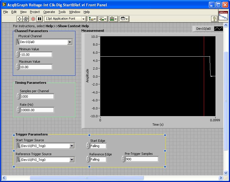
.In fact, the example is the same thing that you need to measure continues - just what you need to do is remove the counter part and replace the trigger reference to be external (your stop trigger).
with this approach, you should be able to do the continuous measurement - I noticed that you need DI - in fact with few changes you should be able to use this example. DI does not have its own timing engine, that's why you should use the external sample clock. If we use the example to create dummy HAVE to provide the sample clock, and we start DI task until we start to HAVE fake, then we can get pretty much continuous clock which begins start trigger and stop the trigger of reference.
Take a look in the change - once again, I have not tested, but logic seems to be OK.
with sincere friendships.
s9ali
-
Measure the time of the rising edges of a digital stream using a USB-6341
I have a DAQ USB-6341 map.
I use Measurement Studio (writing code in c#) on a Windows 7 computer.
I'm relatively new to the DAQ cards, programming, so I could ask something that is obvious (sorry if this is the case).
I went out a stream of digital pulses to an analog output channel. I wired this channel to one input of the meter channel. I am able to measure the number of edges upward to the inlet of the meter channel (since the digial flow is continuous, the number of rising edges increases with time).
I would like a time stamp of each rising transition and I like to keep these timestamps in a table without ever growing (or maybe bin these timestamps in a histogram).
Set up the meter channel to provide the timestamp data? (rather than just count)
Thank you for your help.
WRB,
The meter must be able to measure the relative time between the different edges of your signal. To do this, you will take care to set the meter to measure time. It will measure how long a full period of your signal takes. You can configure edge that you want to start with. You'll want to set up your timed 'implied' measure. This sets up the meter to automatically take action whenever a period is over. While it's not exactly a timestamp, you can find the distance between two edges by adding the time periods between the banks in question.
I see another technique that you can use. This would put the counter to edges of County one of the basics of time of your device (it has 100 KHz, 20 MHz and 100 MHz bases long). Then configure the task to use your signal as a sample (configuration to use rising edge) clock. Whenever the song occurs, you will get the number of ticks ticks selected timebase that took place at that time. One thing to note here, however, is that the counters are 32-bit wide, so your code will have to manage the overthrow of this charge if you are using a fast time and base running for long periods of time.
Hope that helps,
Dan
-
Meter output that uses as AO start
Hello everyone,
I am currently using a PCI-6120 with a BNC-2120. In VI I have attached to this post, I have an analog output channel that generates a predefined signal stored in the memory of the Commission. Regeneration is activated so that the signal is emitted continuously.
The generation can be stopped and (re-) started at any time using a switch on the front panel.
Outside this AO channel, there is a counter. I would use this counter as the trigger to start for the AO, so that, when the switch on the front panel is set on WE, the AO task waits for the next rising edge of meter output to start the build.
Here's my problem.
When I run the VI, the first beginning of the AO is in fact triggered by the meter. The two generated signals are perfectly synchronized (AO and Ctr). BUT! After putting the switch to OFF and then back on, the signals are not synchronized more. AO task starts generating right samples after the start of the task, without waiting for the next rising edge of the output of the counter.
Could someone help me understand what is happening, please?
Why it works just after the execution of the VI, but not after using the switch on the front panel?
Thank you very much.
P.S.: when the switch is off, the AO job is not completely stopped. The OD begins to generate a constant value of 0 Volt. It's normal. I want to check the value generated by the Board at any time to avoid damage to the unit that I send the signal. So I force the generation 0 Volt, rather than simply stop the task.
LucG,
According to the S-series user's Guide, the time will be two impulses of your time base clock sample. So, it is expected.
The delay of the 2 tick must be for an internal sample clock. There should be no delay if you use an external sample clock.
You can check whether this delay appears when the sample clock is also used as the trigger for the start. I didn't realize this test.
If it doesn't, I think that your solution will be to buy another Board because I have already spent time yesterday to try something else like using the counter of seconds for example, but it really seems that there is no work around except buy a Board with a more recent technology.
Kind regards
-
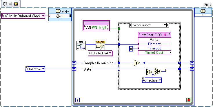
[FlexRIO] Start-up to synchronize several clocks sample
Hello
I tried before, two different (SMU-7962R + OR-5734) FlexRIO card reading in the '40 MHz Onboard Clock' or 'PXI_Clk10' areas of clock. Trigger has been achieved by simply looking for a rising edge on PXI_Trig0:
This produces seeds, but there has no inclination (or constantly tilt at least) between the two FlexRIOs - I sent a pulse train duplicated in the two cards, and the triggered-acquired waveforms were still at the stage:
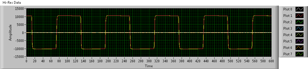
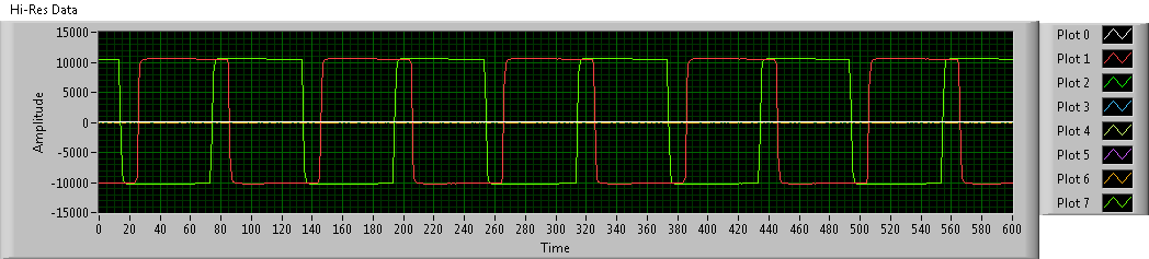
To avoid problems, I went to examples of clock (IO Module clock 0). Unfortunately, the clocks of the sample between the two FlexRIOs had nothing in common, so the acquired waveforms have been is out of phase. Worse still, the phase difference changes with each release:
Looking at the implementation of the library of the synchronization of the FIDL, the classic technique for synchronization of multiple cards FlexRIO seems to be built around synchronization master-slave (my observation is correct?). I was wondering: is there a way to simply share a sample clock shared between cards (like what the 40 MHz embedded clock was doing before), as described in http://www.ni.com/white-paper/11369/en/ ? (I think I understand the disadvantages associated with sample clock synchronization, but I'm willing to try for now).
Thanks in advance!
Hi JKSH,
Page 9 of the Manual 5734 described the different synchronized methods that can be used the 5734. You can synchronize either sample clock of each module to a clock available through your chassis backplane (for example, DStar_A) by allowing the IOModSynClk in 5734 properties (available the Details category) or use an external clock through the Clk port on the module. Activation of IOModSyncClk is probably the best approach and will lead by examples of clock on each module e/s being PLLed on the clock of the town - which must synchronize the clocks of the two sample together.
Let me know if you have follow-up questions.
Kind regards


Maybe you are looking for
-
How can I request the Blocksite add-on to all users at the same time?
I have the Blocksite add-on but I need to change each separated from sweat. Why? is it possible, or he must make each user at a time?
-
Output port headphone jack damaged.
MY helmet was damaged recently or a long time ago, and my apple headphones will not change the audio volume of the right atrium is weird. My other headphones that have two metal strips, not three Jack, still work fine with it. I tested my apple earbu
-
How do activate you the alphanumeric keys?
the numbers are located on the keys alpha e.g. u/4, i / 5, etc.
-
Hi, I found a few good suggestions on how to increase the UDP buffer size in the Windows here, but I could not find all these suggestions for RT - is - does anyone know how to LabVIEW RT? Thank you.
-
Windows Vista can be upgraded directly to Windows 1?
I wanted to know if my Version of Windows Vista, can be improved 'straight' to Windows 10.