9402 internal counters/timers?
Hello
The NI 9402 has an internal counter/timer?
The description of the product on the web page says that's, however the manual so that it does not mention a counter/timer.
Other web searches only refer to a counter/timer, when it is installed in a chassis.
If not, can anyone recommend a USB DAQ for monitor 4 streams (5V, up to 100 kHz) pulse rate?
Thank you
Erik
Hi Erik,
The documentation is a bit difficult - the important thing to note is that the 9402 cannot be used with a USB socket: NI C Series Module compatibility chart. I recommend to visit the DAQ homepage and search by bus and meter number. It seems to me that you can possibly use USB 6501 which has 24 DIO lines, 1 counter and can read in at a rate of up to 5 MHz (and it is a mere $99). If you need a little more which is always close to your price range, you can upgrade to the swankier USB 6210. Hope that helps!
Tags: NI Software
Similar Questions
-
Council of low profile counters/timers
NOR (or someone else) made a profile Board low counter/timer? Perhaps with similar to 6602 record? If no, are there other options I could look in (I think that sampling rate may be too high to use USB)?
Hi greatgrandpadog,
Unfortunately, NEITHER has no counters/timers who are discreet about PCI solutions.
Our location simple cDAQ-9171 chassis USB has 4 32-bit counters/timers can be used by a clock of 80 MHz to edge (detailed specifications). For external signals, you can use one of our module of digital I/o that have different characteristics. You can find a list of them here. This will be the best way to go for a compact USB counters/timers. If you have additional IO, take a look at our CompactDAQ Advisor, where you can use a chassis 4 or 8 locations to develop your e/s in a single system. For a more sophisticated control, CompactRIO offers a similar platform but with FPGA and real-time for greater customization and reliability. There is a line for this even, consultant here.
Kind regards
-
Problem with the generation of two internal counters pulse trains
Hello
I do a control of temperature for two heaters, OR 9472 (output module digital), NI 9271 (RTD for measuring temperatures) and cDAQ-9174 chassis. So, I use the internal meter NI 9174 to generate two pulse train on the outputs (I tried with both cases-> pulse continuous and finite). Before that, I have two separate PID.vi, in which each sent the percentage of cycle of obligation for the two tasks of pulse generation (I configured these tasks with the physical channel cDAQ1Mod1/ctr0 and cDAQ1Mod1/ctr1). The problem is when I run the program, because the application initially worked fine, but after a few seconds the communication between the chassis and the application is not respected (no error message, but the external LEDs on the NI 9472 module had been disabled and stopped too NI 9271 module temperature readings). Then I tried to stop it with a 'Stop' button, but nothing happens. After, I abandoned the race and still nothing happened. So, I finished the Labview program with the Task Manager and a message appeared "reset VI: xxxxx". Finally, I have to restart my computer to run the program again. Can anyone help with this please? If you need more information, let me know.
Kind regards
Hi Luis,.
I have the error cluster connected. But I solved my problem in a different way. I don't know why, but when I configured my RTD module with the DAQ assistant to test some of my design in a new file in VI, the RTD module works fine, but if I copy the entire program logic (include my DAQ assistant) back to my main VI folder and run the application, only for communication between my DAQ hardware and my software works there shortly. So I solved my problem set up any device or module in the same file from the application again and problem disappears.
Thanks for your help.
Luis C.
-
Hello
I use the entrance of counter/timer on a map of 6040E for counting of events.
I use CTR0 and have specified the clock 20 MHz as my source and connected my event at the door (PFI9). I has a finite number of impulses and I am configuration of the buffer using the DAmx Timing (example of clock) vi.
My question concerns the entry of 'rate. ' Counter source is positioned at 20 MHz is not the rate? Can anyone advise as to how to choose a reasonable value and what effect it has.
I usually use the rate for analog I/o buffers in order to fix the rate of buffer - I can't quite see its use in this case.
Thank you
I forgot to go to the part of rates, for counting of events, the rate is how many times buffering you your edge counter value.
IE I count photons a PMT, I would like to see the cumulative number every 1ms so I plug the source on the PMT and run continious at 1 kHz, every second, I read 1000pts and plot. I think that this is how the rate. For measurements, the clock is implied, there is no price since the edges of ascnchronous determines the time to write to the buffer.
-
Amnesty International and counter sync + USB signal stream (USB-6210 vs USB-6341)
Hi all
I'm at a stage of identification of a material suitable for the following tasks:
- 5 analog inputs (AIs) of reading at the same time, tensions at a rate of kSps (at least) 10,
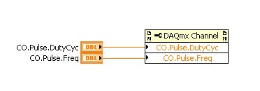
- application captures 2 inputs using timers (detection of contours with timestamps), square wave entry with duty ratio of 50 percent and about 1.5 kHz frequency and variable pulse width / frequency (from 2 sensors hall, representative of the DC motor rotation speed and direction, quadrature signals), resolution of timestamps should be (at least) 50 ns,
- AIs and counters should behave in a deterministic way, and must be synchronized in a way,
- data to be transferred via the USB port of a host computer with Matlab Data Acquisition Toolbox (unfortunately not LabVIEW).
I've identified the long USB-6210 USB-6341 and potential candidates of material to accomplish the above tasks, but after reviewing several documentation and the topics of the forum, I'm still a bit confused, if both are fully working and my approach described below is not working properly.
Counters: I intend to use the internal time base available 20 MHz as being the source of meter to get into account the resolution of timestamp 50 ns. External impulses hall are used as sample clock (about 1.5 kHz, see above). As the pulse width varies, the sample clock is not constant.
AIs: Using a 10 kHz internal clock signal derived from the time base of 20 MHz for timing and analog inputs (trigger) start-up and counters simultaneously material should translate into the required synchronization and deterministic behavior.
It work? Other recommendations?
Next is the USB data transfer: all HAVE 5 and 2 data entry of the meter must be correctly transferred to the host computer (the corresponding rates are shown above). USB-6210 is capable of 4 USB signal flow, device USB X range (6341) offers 8 of them. Unfortunately, I could not understand the exact meaning of the expression "signal flow" still. Do I need 1 flow of input signals (would be 7 for my application described) or 1 stream for all analog inputs and 1 for counter inputs (lead 2 streams for my request). Is there no further details on this approach (more than Streaming of signals of NOR) USB signal flow?
Any challenge to the described application that I might have forgotten? 6210 USB seems to a very limited number of entry PFI, maybe even too low for my meter participate application?
Looking forward to your comments and advice.
Concerning
jAwA
1. I recommend the X-6341 series on the M-series 6210 sake of counters/timers. It is more of them, and each of them is more capable. It can also have a great FIFO embarked for meters that may be important in certain tasks, although I don't think that you currently deal with one of them.
2. your general concepts on timing & sync are satisfactory. You will be able to share and to route signals that help ensure synchronization and determinism between the timestamps for your various tasks. Note that for meter entry tasks, you need set up the trigger 'Arm Start' rather than the regular start trigger.
3 is not authoritarian, but I believe that the flow of signal # will correspond to the tasks #. For you, it would be 1 task of HAVE and tasks CI 1 or 2. (Not clear if you have 1 Encoder with 2-channel quad that would require 1 task of CI, or if you have 2 encoders with 4-way quad).
4. pay attention to the hall effect signals that are not virgins. Digital filtering is available and probably better on the X-series, the series M.
5. strictly speaking, edge detection is a type of digital input task that produces samples but no timestamps. Ideally, I would like to parallel wires on the two digital inputs for the entries of detection and counter change to position quadrature decoding. Then I would sample the counters Encoder 1 or 2 using the internal pulse 'event of detection of change '. I would create another counter timestamp change detects pulses as well.
-Kevin P
-
How to speed up loop DAQ triggered using NOR cDAQ-9174 with NOR-9215 and NOR-9402
Hello
I use LV2010 and NOR-DAQmx 9.2.2. I have a NOR cDAQ-9174 with a NEITHER-9215 4 channel 100 k simultaneous ADC and NOR-9402 4 channel DIO module trigger and reset.
We run WinXP sp3 on a Dell M4400 core 2 duo @2. 26 Ghz.
I used the code example NI DAQmx for acquisition of tension with trigger HW. My goal is to try all 4 channels on the 9215 simultaneously when a trigger is received on channel 0 of the 9402, after data is read, I use channel 1 on the 9402 to reset the trigger of the target material. I have a version of this work, however the maximum event rate is ~ 16/second. I have the Setup 9215 for finite samples / 10 samples per channel which is ~ 400uSec of conversion time and I realize he is above in the appeal of vi, but ~ 50mSeconds worth?
The target detector can put out up to 1 k / event triggers / seconds. Only, I received a rate of 8 per second and I added the NOR-DAQmx control vi driver and chose "commit" this did double the rate.
My question is what is the maximum rate of loop for these devices (trigger/conversion/reading device / reset) and start over? I noticed that just let free the 9215, carried out using the 'Acq & chart internal strain Clk' raised only the rate of events up to 20 Hz.
Thank you
normbo663
Hi normbo663,
You can get this works far better assuming you have an available counter (there are 4 on the backplane of the 9174).
DAQ Compact supports the tasks of meter output "redeclenchables" that can be used to generate a finite pulse train. You can set a task of finished meter redeclenchables output to be used as sample for your task of analog clock. The task of the meter output will be re-Army (less than 12, 5-25 ns) as soon as it's finished out the last pulse. The task of analog input would be configured to run continuously, but it would only sample based on the output of the meter triggered. For an example, see here.
You can reference the internal counters on the cDAQ without signals through a routing module using: cDAQ1/_ctr0 (right click on the chain counter control, then select i/o name of filtering and check channels internal to add these options to the drop down).
Thus, with the tips above, you should be able to immediately re - arming your analog acquisition on the 9215 using one background basket counters. It seems that the second half of the application is to use a second channel on the 9402 to reset the trigger of your DUT. You can deterministically generate this signal so by configuring a 2nd redeclenchables meter out task (single pulse, but this time). All you need to do is the initial delay on the appropriate value for your analog acquisition. Trigger this counter on the same PFI line that trigger you your analog task from.
Using counters to generate the signals you need in a deterministic way, the loop becomes is no longer a problem (as long as your input buffer does not overflow). You may need to re-read several triggers at the same time for the loop to keep (for example to read 1000 samples each, which would correspond to 100 triggers 10 samples).
Best regards
-
Hello
I've created a dll com in VC ++ using performance counters/timers to less than a millisecond.
This is useful when you send a message to very high speed. (say 10 or more)
This is done by the dll.
When I use CVI to create a user interface, this dll runs at a fixed rate of 1ms.
This slows down the application.
I tried to use the same dll with VC ++ host and it works well.
I need to check the registry setting to see if the useDefaultTimer is set to false or TRUE.
(I'm not near the development PC) However, by default, it should be FALSE and I have no fidle with it.
Veuileez post any suggestions you might have.
Thank you!
This problem is now solved for me.
Just the highest thread priority in the dll.
Thank you if you had the answer.
-
How to use an internal counter of the cDAQ-9172 for measure PWM and generate the frequency?
Hello
Requirement of my project is to measure 6-channel PWM and generate 5 frequency channels.
Suggestion of engineer OR bought cDAQ-9172 chassis and NI 9423 (8 DI correlated) and NI 9474 (8 correlated DO) for this requirement. I have a few questions
Article:
1 > what should I know to customize my CompactDaq 9172 chassis
http://zone.NI.com/DevZone/CDA/tut/p/ID/9367
I know that this way to synchronize the physical support 32 correlation system pin o for housing 1-4.
=> I'm not really sure how to use these channels synchronization support.
2 > using internal counters on one NOR cDAQ-9172 as a sample for other tasks clock
http://digital.NI.com/public.nsf/allkb/ADFC4DD8C9690232862575B70079FBD4
I know that I can change the ownership of the physical channel so I can get 2 meter outside the frame 6 and 7.
=> I do not think that this solution will be me because I can use only 2 counters with this method.
Could someone tell me please how to fix my project requirement? How to choose the setting for DAQmx screws?
I have experience with measure the PWM and generate the frequency, but with separated against only.
Best regards
Thang Nguyen
Hey Thang.
AHA... for this, you can use the channel property node.
See you soon
Lab
-
source timebase external meter in the task of separation of two edges
Hi all
I use a Board OR 6220 and want to make something very similar to what is described in the knowledge base article "how I count Digital edges between Start and Stop relaxing on a NI 6602 Council of counters/timers?
Anyone know how I change the example program "TwoEdgeSep.c" do not use the internal time base but to use an external source (that I want to count the edges?)
Thank you for for your time.
ULI
Hi Uli,
You must add a call to DAQmxSetCICtrTimebaseSrc before starts the task to configure the hardware to use an external time base. You also probably want to change the DAQmx_Val_Seconds
DAQmx_Val_Ticks parameter in
the DAQmxCreateCITwoEdgeSepChan
function assuming you want your result measured in terms of the external clock ticks.Best regards
-
[HP Photosmart C4480] Reset NVM
Hello
I have always been satisfied of this printer, simple to install and to truly "plug and play".
I recently started to print more often and all of a sudden the printer complained "Incompatible cartridge".
It was very strange because I have a 50 page document printing and the error occurred in the 9th or 10th page without no reason.
I tried changing the cartridge with another, their cleaning and restart the printer: no change.
I googled the error message and found to be a "semi-Full Reset" could help... without success.
I tried all the combinations to enter "special Key Combo" and found several menus.
I found a few jokes like 'Underware' and ' Fix me! " (I love Easter eggs) but also some very promising elements as 'clear the nvm,' several 'disp ID xXx', 'test', 'against', 'enter serial number... "
As my title, my last attempt to fix my problem is to reset the permanent memory.
Do is to reset all parameters to their default value and the printer should return to the same State when I bought it.
The fact is that when I "erase the NVM", the printer displays the following message: "it is not the default serial number. Cannot reset NVM. "
I checked the serial number printed on the back of the printer and compared to what "serial number" (information menu) displays.
They match, but the latter is longer and I do not know where the last 4 digits.
I found the menu I want to change the serial number, but as I do not know what series 'default' to enter, I'm stuck.
So I would like to know what serial number of entry or, more generally, how to reset my printer's nonvolatile memory.
If the instructions depends on the serial number of my printer, you can send me a PM.
I hope that my message is quite clear and perhaps help others solve this infamous error "Incompatible cartridge".
If you need more information, let me know.
Kind regards
I finally found an easy way to reset the permanent memory.
I put an SD card in the printer, which is held on the Cancel (red X) and the power button and press the blue, gray and green (in that order) to have access to the menu 'Underware '.
There, I went into the menu "photo" and pressed OK the "dump nvm = > file ' point.
I put the SD card in my laptop and edited the NVM_0001.DMP file (in the NVM2 folder) with a hex editor.
I replaced every value of 0 for the emptying of the NVM was filled with zeros.
I renamed the file NVM_RAW. DMP and put the map SD card in the printer.
I did the same thing as above to access the menu "photo", but instead of dumping the NVM in a file, I did the opposite with ' file dump = > nvm.
I rebooted the printer and that is!
NB: It does not solve the issue of the "Incompatible cartridge", but at least, the internal counters are now at 0!
-
Photon counting using Photon unique cash Module and PCI-6602
Hi all
I am currently working on program couting of photons using a single (Excelitas) and PCI-6602 photon counting module connected to the BNC-2121.
I took a glance at other positions, but I still couldn't solve my problem (or, again, I'm not sure if yes or no, the problem is the specification of the material).
In the program, I'm generates a trigger to 1 MHz pulse using a trigger in a separate loop.
Other than that, I have loops of the producer-consumer model to get data and do a simple subtraction to calculate the number of photons in 1 microsecond.
According to the values connected to 'Input.BufSize' of buffer DAQmx and "Samples per channel" DAQmx calendar, I could change the loop number that the program has done its job correctly.
With the values, the program acquires photon 1 MHz with signls for 139 times.
After that, the program stops and the loopback number increases very quickly.
When I forcifully took stop the program, while the loop number increases very quickly, the program appears "error-200141".»
The error that says "data has been replaced before it can be read by the system." Mechanism of data transfer is interrupted, try to use DMA or USB in bulk. Otherwise, divide the input signal before taking the action. "even if the meter explicitly works in DMA mode by using the sample clock.
I wonder there is nothing that can solve my problem or even the only solution will buy a better Board of counters/timers.
Thank you all for reading this.
I will be very happy with any index

Kind regards
Myeongsu
Yes, the same thing happens on my system.
It does not happen with PCIe-6612.
I found more strange things:
When I start to reduce the frequency at a time given (800kHz) can fill the buffer, it will not start since the beginning of the buffer. He can go to the beginning of the buffer only at 100 kHz for my PC.
Options to fix:
(1) PCIe-6612. Seems to work. I tried streaming at 10 MHz, 5 min - fine.
(2) reduce the frequency of the pulse. If your laser supports 100 kHz, you're fine.
(3) put in place additional synchronous counter at 100 kHz. Basically, it's material average number of photons by 10 pulses.
(4) read 2 adjacent pulses each 1/50 kHz - then your data transfer will be 100 kHz and you will get the number of photons of this impulse of the 20 - th.
Programming issues:
(1) remove the display of the received picture, make only the processing of data and show results if you really need it.
(2) clock.vi sample sets the buffer size, if you specify the size of the buffer, do this after this vi.
(3) I deleted unnecessary "loop generation." He is running on the hardware and stops when you stop it - after reading the loop ends.
-
Implement a timer on an SMU-6361
I need to implement a timer by using one of the counters/Timers on a SMU-6361 Multifunction DAQ module. I don't find any help on the web view OR to implement the timers. I guess to study the manual of the X series that I would use the single pulse generation with trigger function. I need assign a clock shipped as SOURCE, assign an entry PFI as the DOOR (Start Trigger), set the value of the impulse for my timing delay, define the pulse width and assign a PFI as the OUTPUT Terminal. However, I can't find any information about what nidaqmx functions I would use to perform this action.
Can anyone address this operation?
wkesling3 wrote:
All examples of OR are for the meter entry tasks. Everyone says to use the example of counting digital event that needs to be changed to make it work.
It of weird, is it some sort of filtering option in CVI? I have examples of ANSI C meter output to:
C:\Users\Public\Documents\National Instruments\NI-DAQ\Examples\DAQmx ANSI C\Counter\Generate Pulse
I took out the DAQmx calls from the code you have written so that they are easier to see on the forum:
DAQmxCreateCOPulseChanTicks (EchoTaskHandle, chan, "", "/ PXI1Slot3/20MHzRefClock", idleState, initialDelay, lowTicks, highTicks);

DAQmxExportSignal (EchoTaskHandle, DAQmx_Val_CounterOutputEvent, "/ PXI1Slot3/PFI3");

DAQmxCfgDigEdgeStartTrig (EchoTaskHandle, "/ PXI1Slot3/PFI4", DAQmx_Val_Rising ");

DAQmxStartTask (EchoTaskHandle);
I see only a few small changes to make:
20MHzRefClock is not a valid terminal, you probably want to use 20 MHztime base.
Instead of DAQmxExportSignal, I use DAQmxSetCOPulseTerm. The output is already on one of the default PFI lines (depending on the meter) and setting the output of an explicit PFI line will change the output terminal. Export the output event counter I think sends the output of a second terminal (I'm not positive if flippant... calls might actually be equivalent, but DAQmxSetCOPulseTerm is most commonly used).
You define the task to be redeclenchables if you intend to trigger the exit several times (DAQmxSetStartTrigRetriggerable). You could alternatively, you can restart the task after each trigger in software, but this is inefficient and you will have several ms downtime compared to the redeclenchables task which will be immediately re-army after the release completed (within 10 seconds of ns anyway).
wkesling3 wrote:
Hi John,.
When (or why) would be the next function call used when the output is already

    defined in the DAQmxCreateCOPulseChanTicks()   function call.

//

  DAQmxErrChk (DAQmxSetExportedSignalAttribute (taskHandleDist,

                                                                    DAQmx_Exported_CtrOutEvent_OutputBehavior, DAQmx_Val_Pulse));
The meter has in fact two different modes.
"Toggle" is the default value for the tasks of the meter output, in which the output of the meter will switch to the opposite value when it reached number of terminals (how a new value is loaded into the account register and the meter begins to count down). So in your case, 'Initial period' will be loaded first, then when the meter lorsque le compteur atteint reached TC output will rise to high and "High Ticks" is then loaded into the registry. When the counter reaches TC again the output will switch down (and in your example pulse, the output will stop - in the generation of pulses multiple 'Low Ticks"would be then responsible).
"Pulse" mode the meter emits only a short pulse (I think 2 ticks long timebase) when it reached TC. It is used by default on meter entry tasks (for example the meter output can serve as an event to detect overview for the tasks of entry conditions). Exit tasks can be configured to "Pulse" too, but in this case the names 'high ticks' and the ' weak ' are unsuitable because the output signal is high only for a very short time (they would be more appropriately called "interval 1" and "interval 2" or something like that).
Most people just use the default behavior and explicitly set the output behavior unless they have a reason to change the default (which is rare).
Best regards
-
Limitation of routing PCI-6602
I'm trying to use 4 counters to generate 4 signals, synchronized with external trigger (PFI, 38). If I use 0 to 3 meters, it fails to build a road linking the counter 0 internal output with the outbreak of departure of 1 meter. - like on the extract attached.
If I use any other counter (4 to 7) instead of counter 0, it works fine.
I couldn't find anything by banning the first NI Max table of routes of the devices configuration. It shows only ArmStart trigger connections, they are directly connected to the outputs internal counters if in the same half (0-3 or 4-7) and through trigger when the other bus.
Is there a way to establish a configuration like that without trying? Me read something wrong, is he full routing documentation somewhere?
Mx 9.3, MAX 5.0 data acquisition
An output meter task finished (at least 2 pulses) requires 2 counters on the 6602 (a counter to generate a signal square output) and the second counter to her door exactly when he finishes the last pulse. Consecutive meters are matched together to this effect (ctr4-ctr5, ctr0-ctr1, ctr2-ctr3, ctr6-ctr7). You run problems because ctr1 generates 2 impulses and therefore requires the use of ctr0 to achieve (if ctr0 is used for your other tasks it will not work).
New hardware STC3 as series X and CompactDAQ a paired internal counters (not accessible by the user), which makes the camera seem to be able to generate an output meter finished with a single meter.
Best regards
-
Rotary decoder in real-time and 'pulse shifter '.
Hello world
I'm putting in place a rotating decoder for use as a shifter of pulsation by labview real-time.
Basically, this means I have two input channels (ttl-legumes, ~ high 20us) rotary engine. A channel contains a pulse at each CA (angle cranc) ° up to 12 kHz (increment). The other channel contains a pulse every 720 ° CA (the charge cycle, BDC_cc low break-even point). With this information a pulse to be generated on an output also channel ttl (high), which triggers my setup of measurement. This impulse must be moved in a programmable relationship to the entrance of BDC_cc, which aims at a table of regular measure.
I got it running by streaming the channel of BDC_cc until a rising edge is detected, then count the edges of increment to the designated trigger point and then generate a pulse on the output channel. The problem is that the late 70-120us exit trigger. In short it's too; a maximum error of ~ 20 is acceptable. Digital channels appear to work faster, so I put discarded Counter-based acquisition.
I'm quite new to LabView, so I'm sorry if the answer is obvious...
My purchase setup consists of:
PCI-MIO-16-1
BNC-2120
LabView 12.0
Max 5.3.1f0Widows XP
This configuration seems to exclude some options Labview offer, such as the external digital acquisition sampled or externally triggered by the acquisition in the base. A manual interpretation of analog inputs is way to slow.
I have attached my working version.
Any input appreciated woud...
John,
I only have a minute right now, but think I can play with a device simulated tonight or tomorrow.
I'm quite sure that there would be a clean solution clocked by material if you use a series M or X-series
Council MIO, but the older generation counters timers on the set of the E series do support everything which
You need. It's been a while since I had to rely on this generation of hardware.
I think the basic approach is to use the lunatics of angle as the clock pulse train that defines the
delay time of the pulse you want to generate. You could be "Timer" the pulse based on the real
angular position, helping you synchronize to a specific angle of crank. The question is whether and how E-series
counters of takes to support the generation of pulses triggered (or redeclenchables). If they are not, I would say that you consider
get new hardware DAQ which support this kind of trigger and you give a very precise pulse
implementation.
-Kevin P
-
buffering overflow of FIFO County edge even at very low rates
Dear Forum,
I try to use a PXI-6608 timestamp clock of a PXI-4498 for the analog input sampling. Because the sampling frequency will be the order of 20 KHz, I want to use a task of impulse generation on a counter to divide down by a factor of 1000, then use this pulse the door and the clock 10 MHz on the 6608 as source contour buffer - I wait about 20 edges per second, which should be handy to collect more DMA.
The result is that I get the error-200279 ("attempt to read samples is no longer available") immediately after the beginning of the vi, before that I extracted an indictment.
This is my first shot of dagger to using DAQmx for counters/timers rather than the old drivers for data acquisition, so I do not know I did something wrong, but I can't understand that.
I have attached the vi if that helps.
Thank you!
Case No.
It seems that you have your door and source to the rear. The sample clock should be ctr0internaloutput and the Terminal count edges should be 10 MHz clock. You get the buffer overflow error because the FIFO on the map is only 2 samples and 10 MHz, these are rewritten was faster that a computer could possible pull out of the map.
Maybe you are looking for
-
Greetings, As a beginner of logic, I'm not find logic "Helps" to be very useful. So, I am looking to buy a book that might be more useful. I found a few on Amazon, all very expensive, so I would like to be sure I understand. So I hope I could meet
-
How one manually associate the file with an application types?
I recently installed the Adobe Digital Editions software to download an e-book I bought. It will not open in ADE, and the manual of the ADE advises me to "manually associate the" types with the application of the EPUB files and the subsidies agreemen
-
Hi all I have a mixed environment with os / x 10.4 and windows. Connecting from os / x to windows via microsoft remote desktop no problem, but can I connect from my windows machine to os / x? Greetings from the Germany Chris added: Oops, wrong forum,
-
ProBook 450 G3 (T3L12UT #ABA): you can add video card for G3 450 Probook?
Hello I am looking to buy a Probook 450 G3, a model that only comes with the integrated graphics card. I see that in the manual a dedicated graphics card (if I read correctly) is an option for the laptop. I wonder if anyone knows if this can be add
-
Windows xp on startup does not complete startup.
When starting the pc with windows XP, when the screen appears, there not all icons showing and no cursor. After the stop and start several times, I'll get a full desktop with all icons and a slider screen. then the pc works normally after that.