A signal generated on NI USB-6211 is appearing to the analog input. This is a fault?
OI Luciano,
com respeito a interferência don't do sinal gerado (saida analogica) no sinal lido (entrada analogica) hoje não houve interferência.
Apliquei o sinal gerado e lido em um oscilocopio e ambos are corretos...
Any assunto you mandarei novas questoes. Obrigado...
Tags: NI Hardware
Similar Questions
-
How do I get the analog input signal and send it to output analog (real time)
Hello world
I do a simple task in Visual C++ and I use PCI-6221(37 pin).
Basically, I want to send the same signal of "analog input" to the "analog output".
at the same time (or almost), to make real-time application.
Can someone provide me with sample program please.
I would be grateful if you could provide me with the great tutorial that explains
step by step everything about NOR-DAQmx for C/C++ programming.
Best regards
Khassan
This is my code in C++, you can optimize it if that seems too messy. This code reads the analog input signals and exports it through the analog outputs.
To make this code additional work of the directories include and library directories must be added to OR.
I hope it helps someone.
#include
#include
#include "NIDAQmx.h".
#include#define DAQmxErrChk (functionCall) {if (DAQmxFailed (error = (functionCall))) {goto error ;}}
int main (int argc, char * argv [])
{
Int32 error = 0;
TaskHandle taskHandleRead = 0, taskHandleWrite = 0;
Read Int32 = 0;
float64 context [1000];
char errBuffRead [2048] = {'\0'};
char errBuffWrite [2048] = {'\0'};
bool32 done = 0;
Int32 wrote;DAQmxErrChk (DAQmxCreateTask("",&taskHandleRead));
DAQmxErrChk (DAQmxCreateAIVoltageChan(taskHandleRead,"Dev1/ai0","",DAQmx_Val_Cfg_Default,-10.0,10.0,DAQmx_Val_Volts,NULL));
DAQmxErrChk (DAQmxCfgSampClkTiming(taskHandleRead,"",100.0,DAQmx_Val_Rising,DAQmx_Val_ContSamps,0));
DAQmxErrChk (DAQmxCreateTask("",&taskHandleWrite));
DAQmxErrChk (DAQmxCreateAOVoltageChan(taskHandleWrite,"Dev1/ao0","",-10.0,10.0,DAQmx_Val_Volts,NULL));
DAQmxErrChk (DAQmxCfgSampClkTiming(taskHandleWrite,"ai/SampleClock",100.0,DAQmx_Val_Rising,DAQmx_Val_ContSamps,1000));DAQmxErrChk (DAQmxStartTask (taskHandleRead));
DAQmxErrChk (DAQmxStartTask (taskHandleWrite));While (! fact &! _kbhit())
{
DAQmxErrChk (DAQmxReadAnalogF64(taskHandleRead,1,10,DAQmx_Val_GroupByScanNumber,dataRead,1000,&read,));
DAQmxErrChk (DAQmxWriteAnalogF64(taskHandleWrite,read,0,10.0,DAQmx_Val_GroupByChannel,dataRead,&written,));
}
_getch();Error:
If (DAQmxFailed (error)){
DAQmxGetExtendedErrorInfo (errBuffRead, 2048);
DAQmxGetExtendedErrorInfo (errBuffWrite, 2048);
}
If (taskHandleRead! = 0){
DAQmxStopTask (taskHandleRead);
DAQmxClearTask (taskHandleRead);
}
If (taskHandleWrite! = 0){
DAQmxStopTask (taskHandleWrite);
DAQmxClearTask (taskHandleWrite);
}
If {(DAQmxFailed (error))
printf ("error DAQmx: %s\n",errBuffRead); ")
printf ("error DAQmx: %s\n",errBuffWrite); ")
}
printf ("end of the program, press the Enter key to quit\n");
GetChar ();
return 0;
} -
How to synchronize the analog input and the output of two different USB data acquisition boards
Hi all
I have two tips very different USB NI USB 6008 case, which I use to acquire the data (analog input) and a USB of NI 9263 is a output analog only site I use to route a signal (in this case a square pulse). The reason why I use the outputs analog 6008 is because I need to deliver negative tension and need the full +/-10 v range.
Looking at similar positions, I'm pretty sure that I can't use an external trigger or a common clock, I also tried to use the timed synchronization of the structures but no cigar.
I'm including a quick vi I whipped showing how the jitters because of the lack of synchronization signal. The OD of the 9263 connects to AI in the 6008 in this example.
I talked to a specialist in the phone and tols me that's not possible.

-
diving USB hard drive appears on the Control Panel, but not on MY computer
Drive hard USB part on the Contrlol Panel but not on my computer.
Hi Frank,.
Thanks for posting your query in Microsoft Community.
If I understand you correctly, the external USB hard drive (HDD) appears in the control panel but does not seem to be detected in my computer screen. I will certainly help you to question, however, I would be grateful if you could answer a few questions to refine the question in order to provide you with better assistance.
(a) what is the brand and model number. the USB HDD?
(b) has detected before HARD drive in my computer screen? If so, did you do changes on the computer before this problem?
(c) that you get an unrecognized USB device notification error message?
The unit is probably go up at the same point one of the partitions and thus becoming "invisible". In
in order to further diagnose the issue, I would suggest trying the following methods and check if the problem persists.
Method 1:
Try running the Fixit tool from the link below.
Hardware devices do not work or are not detected in Windows
Also, run the next fixit to solve common problems with USB devices.
Diagnose and automatically fix the Windows USB problems
If the problem persists, try the following method.
Method 2:
Remove and reinstall all USB controllers.
- Open Manager devices by clicking the Start button, click Control Panel, click system and security, and then, under System, clicking Device Manager. If you are prompted for an administrator password or a confirmation, type the password or provide confirmation.
- In the list of the categories of equipment, locate and expand Bus USB controllers.
- Right-click every device under the Bus USB controllers node and then click Uninstall to remove them one at a time.
- Restart the computer and let the USB controllers get reinstalled.
Plug in the removable USB device and perform a test to ensure that the problem is solved
Also, refer to:
Updated a hardware driver that is not working properly
Hope this information is useful. Let us know if you need more help, we will be happy to help you.
-
USBs will not appear in the virtual memory
I have a 16 GB Sandisk usb, now the drive letter is 'H', which is very well and is in fat32 format. This usb does not show in this tab advanced virtual memory for windows 7 x64bit. Just my c, d, e, which is a HHD.
You cannot use virtual memory on removable media. However, you can use ReadyBoost. Open the folder on your computer, click the drive and go to properties, and then use the ReadyBoost tab to activate the additional memory of this flash drive.
-
USB-6211: analog input signal affecting another of the same map AI
Hello
I use the DAQ-nor-6211 map and DAQmx features to read a hammer and a signal of the accelerometer and then use other LabView functions to make the FFT of these analog input signals. However, it seems that the analog inputs where the hammer and the accelerometer are connected generate a kind of noise or influence in other entries of this data that is not connected to any other sensor acquisition board.
I've had different experiences in order to check if the problem is with reading the card: put the accelerometer and hit the dog in another table where the DAQ card table was located (to avoid the vibrations on the map and a possible noise), ai1 entry was logged on the differential mode on the dog and the ai4 of entry is connected to the output (z axis) of the accelerometer. The other 2 ai2 and ai3, entries that can also be read by my LabView program, are open (i. e., any other sensor is connected to the card). When the structure where the accelerometer is located is struck by the hammer, the signal of ai2 ("x axis" seen in the first attached document) has a curve (on the time domain) which initialize almost at the same time that the hammer and the a3 of entry has a weak signal, but with the swing as well as the signal of ai4. The document "hammer ai1 + z_axis connected_ _x_axis disconnected ai2 + y_axis ai3 ai4" images that I captured the chart created in LabView. On these graphs, it is possible to check on the FFT the ai3 signal and ai4 has the same behavior (with different intensities), and enlarged figure of time domain image, we can see that the signal of ai2 increase almost at the same time of the signal of the hammer (ai1). The signal picked up by the sensors are probably creating a sort of noise on open entries ai2 and ai3.
Another experiment was conducted to check if the signal from a single entry that may affect the signal read from each other near the entrances: the DAQmx task Create channel had a physical channel has changed: ai3 entry has been modified by ai7 (maintain the same connection mode: differential), and the results are visible on the second attached document. In the graphs obtained in this experiment, it seems that the entrance of the hammer (ai1) affects the signal of input ai2 and ai7, which are not connected. And the ai4 signal does not seem to influence the other inputs, because he has a different curve on the graph of the FFT.
The same experiment was conducted using the CSR connection (change threads and create the DAQmx Channel Configuration), but the results were the same as those found using differential connection.
Finally, if the output of the accelerometer is connected on the ai2, the signal of the other open entries ai4 and ai7 seem to be affected by the signal of the accelerometer on ai2 (last document attached).
Could you tell me if the problem I encounter is caused by the DAQ card with this information that I gave to you? And if the answer is Yes, do you know if there is a way to avoid this noise create in one entry on the other hand, it please?
Thank you
Maybe Ghosting or crosstalk? Just an idea.
-
NEITHER USB-6211 signal to noise
While using the analog inputs of the device USB-6211 (Labview 8.5 / Win 7) signal become noisier. By surprise, I got a signal perfect after you have disconnected and reconnected the USB card to the system. This behavior is reproducible for the cards (n = 4) that we use in our laboratory. Is this a known issue with the 6211 card and if so is there a method to reset the map using labview?
Thank you!
Christian
Christian,
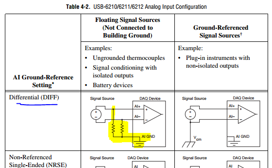
I'm glad that you have solved your problem. Manuals for most of the DAQ cards NOR recommend resistance of two entries to HAVE to AI GND to ensure that a path suitable for polarization currents exist when it is used in differential mode.
Lynn
-
Strange analog output of USB-6211
I just got USB-6211 to replace USB-6001 to set the clock to external sampling on analog output for LED lighting control. The part of external clock example works fine, but the analog output voltage is strange. To do self-monitoring, I connected control pin LED to AO0 & AI0 of surveillance in the NI MAX test panel and LED control on the ground at AO - GND & GND HAVE since I have both USB-6001 and USB-6211, I conducted tests on two of them with the same setting of wire. When I generate sine wave - 5V to 5V to AO0 (from NI MAX test panel), USB-6001 can monitor the same signal AI0, but watch USB-6211 - 3, 4V to 3.4V voltage truncated. I did the test separately (wiring one device at a time), so there is no interference between the two devices. USB-6211 past self-calibration and self-monitoring. Also, I did reset devices. I don't know why they would behave differently with the same configuration, and I hope that someone could help with this question. Thank you.
Hi skuo1008,
The USB-6001 can support + / 5 output current my from terminals to analog output, while the USB-6211 box can provide only +/-2 my current output. It is likely that the load impedance is too low, causing the 6211 to hit its current compliance and thus cut the tension. If you try to exchange your load with a resistance of at least 5 v/.002A = 2500 Ohms, you should be able to see the full +/-5V sine wave. I suspect that your DUT has a words 3.4V/.002A = 1700 Ohms impedance. You could use a device with higher output current or use a more current source buffer circuit. If you do not need a bipolar output, you might also consider using digital lines to control the LEDs.
Kind regards
-
Hello
I use an NI USB-6211 device, Windows XP, and I have the problem of blood (photo attached).My analog differential signal (signal DC to DC power supply) is connected to an analog input in box usb-6211 (AI1 and AI9 ports).
The signal I get is evolving between 0V the Volt of entry (in the attached photo - 4V) instead of 4 v DC.
It might be a good idea to test it with a 9V battery using a differential connection with wiring configuration described in the manual (photo and link below). I know it sounds Basic, but re-seats black connector of i/o to the device might help. Make sure you reference GND AI as well.
-
The sampling frequency is divided between channels USB-6211
I use a USB-6211 DAQ card. The jury is announced with a rate of 250 kech. / s. I started to take action with 2 channels and could not get the frequency of sampling of 125kHz, then when I tried to make measurements on 5 channels, I could get a maximum of 50 kHz sampling frequency. This figure of 250 kech. / s is really the sum on all channels, or is there a way to get that channel?
I have only a simple Laview program with a while loop, 1 assistant DAQ entry with 5 channels, assistant DAQ 1 exit with 1 output channel, box 'Relaxation and door' to catch a progressive input signal, a smoothing filter and graphics.
250 kech. / s is an aggregation rate as shown on the first page of the document specifications. This means that the device has a single A/D converter that is shared by all channels under analysis. According to th etime to the multiplexer and all time for the internal amplifier, your maximum rate may be slightly less than 250,000 / N where N is the number of channels.
Lynn
-
Ive got an acquisition of data USB-6211 (and LabView 2009) and Im trying to get the output (5v) device to run a relay on and outside. IM using a tutorial I found on Internet to make the diagram Labview (http://www.pages.drexel.edu/~pyo22/mem639/lab-usb6211DigitalInputOutput/lab-usbDigitalInputOutput082...) and the circuit is simple. I tried to run the DAQ Assistant to test if my output was working, and it is not. I'm not sure if my connections for data acquisition are correct or not. Any help would be useful.
Thank you.
Hello NT_Mech,
Indeed, it is possible that you do not drive enough current for the relay. You can check the specifications of your USB-6211 and see that the digital line will result in a maximum of 16mA. That being said, your relay control current that is needed, you may need to run the two outputs in parallel to offer twice more common provided. Recently, I drove a Soviet Socialist Republic of a Luminary Micro Prototype Board that did not provide enough current as well. In the case of the tat, I was driving the relay by running two lines in parallel.
You can always simplify the software side of things by opening the measurement and Automation Explorer (MAX) and right click on your device and select test panels. "" ' Start ' programs ' National Instruments ' Measurement & Automation then expand devices and Interfaces. Right-click and select Test panels. You can then configure a digital output for your USB-6211 and toggle On / Off and check out.
Best,
-
Input signal is set to +/-0 .5V when it is connected to an analog input
Hello
I have a difficulty connect an analog source to the analog inputs of my acquisition of data (USB-6215). The analog signal is output operational amplifier through a 10 k resistor. I wore the signal out of the amplifiers is 10V peak, I then move the probe across the 10 k (the analog input terminal) and the signal is clipped to +/-0 .5V. If I reduce the amplitude of the signals of source less than 0, 5V Ridge there is no clipping.
Maybe the analog input range the value +/-0 .5V which is causing this as a form of protection? I don't have a LabView to try to change the input range as I do just the wiring.
Analog source is connected to him HAVE 0 and the ground of the analog source is connected to the GND AI.
Thanks in advance.
J
Joel-
Have you tried to read the data through the data acquisition device? If that's what you try to do, I'm curious about what we read.
If you have measurement and Automation Explorer, go ahead and open a Panel to test for the unit and see what are your tensions.
Let us know how it goes.
-
NI USB - 6212 BNC analog input impedance matching
I just ordered a case NOR USB - 6212 BNC DAQ (should be delivered soon). I want to use to measure HV signals using a probe of high voltage of 1/1000 I have.
Now, datasheet of the probe (not a lot of info) says it has an impedance imput 100MOhm. I suppose that it consists of a simple resisitve divider, and if the ratio is 1/1000, I wait so to have a 99.9MOhm resistance in series with a 0.1MOhm resistance. However, the data sheet also specify that the probe is designed to be connected to an oscilloscope with an impedance of 1MOhm. As this input impedance is very low compared to the low value of the separator of resistance resistance, so I guess that the real resistance at the level of the sensor values 99.9MOhm and 0.11MOhm (to obtain the 0.99 and 0.1MOhm when it is connected to the oscilloscope for 1mW).
Therefore, given that the impedance of the USB-6212 according to the datasheet, the analog input is > 10GOhm, I expect to measure higher to true alternative voltages when connected to the acquisition of data from 10%. This assumption has a meaning?
What would be the best way to get around this? Do a calibration and correct the values acquired in LabVIEW code? Or should I add precision 1MOhm resistance at the same time to the acquisition of input data to decrease its resistance to entry to the value expected by the probe?
Thanks for your help!
Since you have a range of 1000: 1 I guess you also need bandwidth (I have a TEK 6015 A
 ), so you need based on the impedance input, a complex value, means he must not only watch but also the ability to input resistance (1 M). demarcation of the field probes have usually some elements of toppings to match the probe and the input scope. RTFM of the help of the probe
BUT a more serious point is that with your probe, you have a very high resistance. And if you look in the specification of the 6212 you will find on page 2 by mistake ppm in logarithmic scale graph! and even 100 k source impedance it not shown.
So I'm afraid that a simple 1 M on the DAQ entry can work if you're only measuring DC, and only if you use a channel on the acquisition of data. A workaround is an amplifier separate buffer with an impedance of good entry corresponding to the specification of your probe and a low output impedance.
-
USB stick not recognized by the computer. Have tried all the options I can think about.
Very well. I have a S-Mini Patriot 32 GB flash drive that does not recognize my HP Slimline 400-434 Windows 8.1. In my view, he acknowledged once and has refused to do since. My laptop (Windows 7 Toshiba) recognizes very well.
All other devices USB function perfectly on this computer. USB hub mouse, keyboard, USB, cable Apple iPhone.
1. I tried to unplug all other USB devices before trying this one. IN CASE OF FAILURE
2. I went to device management and the USB does not appear in the list. IN CASE OF FAILURE
3. I uninstalled the USB root hubs and restarted the computer. IN CASE OF FAILURE
4. I tried to plug in the USB ports on the back that plug directly into the motherboard. IN CASE OF FAILURE
5. I have updated the drivers, and have been unable to find a update of the BIOS as the link on the HP download site and told that it is incompatible to my computer. IN CASE OF FAILURE
.. then what the hell gorram bloody I do now?
Good and the most ridiculous way, I never solved a technical problem...
Failed to insert the USB flash in the port. She has to insert slowly, so that the contacts are aligned.
I found it trying to connect to it in my USB hub and noting that the witness red light was going on and outside that I inserted the USB key, flicker on as I inserted it there and then off once it is all the way in.
Weird. But good. It works now.
-
How to compare analog input signals?
Hi all
I use PCIe6363 DAQ to collect the analog input signals. Mode of input signal is continuous and single channel several example. The sampling frequency is 2 ms/s, number of sample 100KS or less. This means DAQ 100KS of collect and draw a line/curve. I want to compare the two curves. The problem is DAQ continuously collects data and plot also continuously. Would you please is it possible to compare the curves of this operation continuous operation. The main goal is to justify whether or not the signal of incomeing maintain consistency.
Thank you very much
Azim
You can store a waveform in a shift register. Then you have in memory compared to the new waveform.
Maybe you are looking for
-
Satellite Pro L300 - webcam driver open failed Please restart camera
I have a Satellite Pro L300.Ive had my laptop for 6 months and tried to get my webcam doesn't work since. When I try to start it, it says "webcm driver open in case of failure please restart computer camera".Ive tried everything, did someone knows so
-
HP Stream: Boot for HP stream order
Cannot change the boot order. When I f5 - 6, it shifts the order, but the little black arrow never passes the initial boot sequence? I have the USB on the top line, but will not boot from a stick? Thank you Nick
-
Hi, I'm new to LabView so I know that the thing I'm doing is relatively easy, however, I'm stuck. I made a small program that gets 5 steps (for now replaced with random numbers) and as well as the date and time data in the text file. I intend to run
-
USB 3.0 port select the pen drive, but does not allow to load mobile
Hello I have acer Aspire V3 - 471G laptop with usb 3.0 port. In this port, it says usb charging device the manual also says it can charge when connected to the laptop via a usb port. If I insert the USB key, it allows to use, but when I connect the m
-
Acer Aspire EasyStore H341 SAAS McAfee not supported
Hello I have an Acer Aspire EasyStore H341 with Windows Home Server build 5.2.3790 software version 1.50 (0953.005). I used it without fail until this week where it is said that McAfee SAAS is not taken in charge on this server more (beginning June 2