Acquisition of analog camera field.
I'm trying to shoot maximum performance of my analog camera. I have a capture card 1405 and the camera is monochrome RS 170 NTSC. In time real LV 2009 SP1. Unfortunately, I have to use to track movement and there is no way at this point to upgrade the hardware. I want to have the minimum image with the blur and as fast as I can get.
Until I can questions, a little intro. RS 170 transfers to each 1/60 s, the odd field (odd lines) and then after the next 1/60 s the same field. Then the framegrabber combines the two to make a complete picture frame providing 30 frames per second and so on. When the movement occurs, because of different time of acquisition, the odd and even fields are once acquired and different and the looks of photo blurred (combing effect). Someone correct me please if none of this is wrong.
Now, why not look the same and off fields and have a 60 fps at 640 x 240? I'm pretty sure that my framegrabber won't let me enter the domain as soon as they come separately. Is this true?
While is simply looking at a field? Odd or even? I don't know how the framegrabber used it for me. Let's say that I have set the mode to the only odd fields. Do the odd field immediately after it happens to the acquisition card or after he gets two odd and even and then it gives me the strange field? In this case, I would get the ground with the delay of 1/60 s, which is bad for me. The start field is the odd field.
I watched an old program that uses analog video. I am sure that the 1405 was supported by the latter, but not positive. The only thing I had to do to enter field mode 60 Hz has been change the 'Interlaced Mode' property to the field.
I understand your pain. Good luck.
Bruce
Tags: NI Hardware
Similar Questions
-
Acquisition of analog and video synchronized
Hello experts tiara,.
I am curious about this example Diadem DAC:
http://zone.NI.com/reference/en-XX/help/370858M-01/explonl/explonl/explonl_dac_video/
He claims to be able to acquire analog and video synchronized. Anyone can determine how to properly synchronize these two data flows are? Because it is a desk, probably Windows machine and no trigger material between video and analog devices, I'm guessing that the two are, at best, on +-1 second.
Can anyone solve this problem? I see in the manual use tiara (here) that NEITHER has done some work in order to study how the clocks are accurate in Diadem. And they even mention a few points of 100 msec. But I don't really trust this number when it comes to acquiring analog and video data simultaneously.
Thank you, John
Hi John,.
You ask an interesting question, and I had contact with the developer of R & D responsible for this service and received an explanation on his part on the works of this feature.
The target application for this specific feature is not for use cases where the exact synchronization between the measurement and data acquisition are required (i.e. a crash test of vehicles with more than 1000 frames / second video recording). This feature is implemented for users who wish to have the possibility to use webcams to get insight into what their machine or test do any recoding data at the same time. We should ask this 'parallel acquisition data and video' and not 'synchronous acquisition' - which suggests that it is a way to ensure that the data and the video are actually synchronized during the acquisition process. The original entered German aid system speaks 'parallel' instead of 'synchronous' acquisition, the English translation incorrectly uses the word 'synchronous' instead of 'parallel '. I contacted our documentation team to clarify this part of the help system.
Accurate synchronization to achieve, especially between multiple streams of data acquisition and a camera, the application must use frame grabber hardware - hardware specifically designed to support the capture video or image.
This is how DIAdem DAC addresses this type of application, I hope this information is helpful to you and others to this feature:
Tiara DAC is a top priority on the acquisition and the release of the data to and from data acquisition equipment. The video recording feature is less of a priority and is not controlled by tiara constantly. The video recording process is triggered as closely as possible to the data acquisition process. The current local time stamps of two triggers (data and video) is registered allows us to determine the exact time for the two signals of reading according to DIAdem, i.e. If there is a delay in the start of video recording, is considered for reading in MODE of DIAdem.
Our tests with made with a camera (not multiple, which is supported by MODE of DIAdem) and data acquisition equipment NOR (not several devices, which is also supported by DIAdem). In these tests, that we have seen the video and data were generally synchronous within some frameworks (no real 100% synchronicity) - which was quite thin which this solution based on USB low-cost camera technology was designed for. It is generally better than +/-1 second depending on the application, but also synchronized to the millisecond like material systems would be able to achieve.
There are several factors that influence the results of the tests carried out in this area of application: PC hardware (CPU, RAM, disk system), the tasks of measures, other software running on the computer chassis, the camera and the framework, software drivers, etc.. There are too many variables beyond the control of tiara that can influence the synchronicity of the acquisition of data and images based on the software only, so true synchronicity can be achieved using equipment designed for this purpose.
I hope that clarifies the DIAdem DAC functionality a little better. Thank your for having pointed out the misuse of the book 'synchronous' in the help system, going as fixed for the next release of DIAdem. Please let us know if you have any other questions.
Best regards
Otmar
-
Watch a video on Qosmio G30 of Hi8 (analog) camera.
One of my reasons to buy Qosmio was to use a TV - to be able to view videos from my analog camera and scan them. But I can't do Qosmio works correctly with my camera. I tried to connect the camera through the video and S-video, but I get a very bad quality image (not color!). Why is this? When I connect my camera to a TV, it shows very good image. I thought that with the Qosmio, it will be the same. I was wrong? In addition, the manual says you should use WinDVR software, but it was not installed (I had to buy it and install it). Can someone help me to connect my camera to Qosmio and operate well (please, instructions step by step)?
> can't do Qosmio works correctly with my camera
First of all, I think that you can't do your camera works properly with your Qosmio. For me, it's a very important difference. I connected my digital camera for Qosmio G20 and saved material recorded everything on the HARD drive. Later, I used Ulead Movie Maker to create a DVD.
I have also the same tested with VHS recorder connected to my Qosmio. I was able to copy all the old movies on the HARD drive. Connect your external device on port antenna Qosmio (VCR VHS). You can watch the material recorded on Qosmioplayer or using Media Center Edition. Cam switch to play mode and at the same time start scanning on Qosmioplayer or Media Center edition channels (your choice what you want to use). In my case, MCE has based the image on channel 33, and image quality was very good.
To connect the digital camera I used the firewire port. Can you do the same? My Cam is recognized automatically and also shown Ulead Movie Maker as signal source. Copy and video editing was a piece of cake.
Please try all possible options. I also tested record with Qosmioplayer. It works well, but I think that the image quality is not very good.
-
Acquisition of multi camera (USB)
I make attempts to acquire data of Sentech twice camera using USB. By program, I was not able to do this in Labview 8.6 since the two devices share the same name. Pleasee the attached screen shot. Does anyone know of a work around or a solution to this? Acquisition of a camera works fine, the passage from one camera to the other is the problem.
Hey gisele,.
For more information, see this KB: to access multiple USB cameras that have the same name.
-
How to change the acquisition on GigE Camera settings in VBAI
I have a line scan application where I need to control the rate of the line depending on the speed of the machine. I use Vision Builder (Vbai) 2009 and I have Labview, but not the Module's development of Vision. I use a custom Labview User Interface for VI. The camera is a camera of IRLS Basler Runner RUL2048 - 30 GM GigE. I created a Labview VI, who wrote the price of line and it works, however when Vbai executes the step of acquiring Image GigE she ignores everything I wrote to the camera and use the parameters that are defined in the step to Aquire Image itself.
I tried to create an Image Acquisition VI in labview, but when I run it in Vbai, there is no image output to be processed.
How do I
(a) make the Image of Aquire GigE "keeps" do not overwrite certain perameters or
(b) acquire an image in Labview and "transmit" to Vbai for treatment
It seems to me that the ability to control the settings of the camera of the user interface is a basic function, but I can't seem to find a way to make it work. Any help would be appreciated. Thank you.
There should be no problem switching between inspections that have the stages of acquisition. Looks like you had an inspection that set the rate of line using a run a LabVIEW VI and I would bet that the session didn't get cleaned properly in the VI you run so when you changed an inspection which attempted to use this camera, the camera was still in use in the LabVIEW that does not have the session closes correctly. I would recommend standard VBAI doing to interact with cameras and then it won't be a problem. When the new step comes out, it will be much easier / cleaner to fix in VBAI.
Thank you
Brad
-
Acquisition of multi camera (IMAQdx)
Hello
I failed to enter two cameras with the IMAQdx driver. For example, download the sample of "enter and select Mode.vi ', copy and paste a second loop for my second camera (see example).
But the second call to 'IMAQdx Grab.vi' returns an error:
"The error 1074360296 occurred at: IMAQdx configuration Acquisition.vi.
Possible reasons:
NOR-IMAQdx: resources for insufficient transfer (Hex 0xBFF69018) engine. »Sorry for the newbie question, but can someone help?
Thank you very much.
PS: I had this problem with the pilot "IMAQ for 1394", but it is no longer supported... I've improved the Vision Acquisition software to version VASAugust2010, do not know if my problem is caused by this upgrade.
PetitOhu
Must be a problem of bandwidth and you may need to reduce the size of packages.
Looking for support OR with the term "inadequate transfer engine resources", you will find a lot of threads (I hope so).
If this is not the case, let us know here.
Guenter -
Retrigger encoder and acquisition of analog input on the spur of Z?
I have a card PCI-6232 and use THIS angular Encoder on the counter 1 to provide a base mean angle for Internet high speed (50-100 kHz) measures the analog voltage. I use a period of CI on counter 2 to measure the duration of the impulse of Z to determine the length of each measure. It kinda works, but the result is somewhat contradictory. I get about 1 in three cycles without encoder data. I need to find a way to trigger the acquisition to record data for each cycle trigger on the pulse of Z. If you know another way to do this I'd be open to that as well. Thank you, Steve
Hi Sara,.
Thanks for your reply. What I wanted to do was to trigger an analysis of the encoder and an entry at the same time triggering the pulse of z analog encoder. It took a lot of digging through similar samples and after a week of fighting, I thought about it tonight. I'll post this once I clean up the mess. Problem solved thanks to dozens of you ad info and samples!
-
Transfer video from an analog camera
Hi all
I have a Sony TRV418E analog camcorder. It has an A / V out connection & login video S. How to connect the camera on my laptop Dell Insperon that has an IEEE 1394 connection. I have MS Movie maker. Y at - it a connector that would go from the camera to the computer. Would this work?
Thank you... Brims
-
Generation and acquisition of analog signals simultaneously on USB-6212
Hello, I am novice programmer DAQ trying to create (what I think is) something very simple.
I use a box NI USB-6212 and LabVIEW 8.5 is trying to generate a pulse train analog while recording a simultaneous analog input.
My first question is, is it possible?
Since I'm new to this, I use the DAQ assistant in LabVIEW. I can acquire a signal, I can also generate the desired signal, but I can't seem to operate simultaneously.
I have been successful in obtaining my program to work with both USB-6212, but I have to be able to do this with a single.
I have attached the block diagram and vi, I hope that's easy to answer the question, even if my research so far has left me empty handed.
Any help would be greatly appreciated!
Jon L
Hi Jon,
Well, first of all welcome to the DAQ programming! I took a peek at your code and published it with a device simulation very well, so I ran with the PCI 6251 card in my computer and he did not also get errors. Could you post the error code you get?
If I could figure out what is your error, I would say you encounter errors of buffer because it is too much overhead in the DAQ to wizards in the face of data rates. My suggestion would be to use the example called "Multi-Function Synch AI - AO.vi. This program can be found in the Finder for example of NOR (see Help"find examples in LabVIEW). "" It appears in the input and output material"DAQmx ' synchronization ' Multi-Function.
Can you give that a try and let me know how it goes? Thank you!
-
Qosmio G10 video capture analog.
Help, please!
Is someone can help me find a way to run analog video capture on a Qosmio?
I need to transfer a lot of analog video from a camcorder, I tried winDvd, Moviemaker, I installed Magic Video Deluxe Pinnacle Studio 9 version complete, but it seems that no one of these software is able to recognize and capture the video source. Only the digital acquisition is OK. It's very frustrating!Thank you very much
MassimoHi, I have also just spent the last two hours trying to capture video from my analog camera. I can't understand how to do that either. I can watch the video on my screen to switch signals with Fn + 4, but I can't access the video signal via any software.
Has anyone else got this yet understood problem?
-
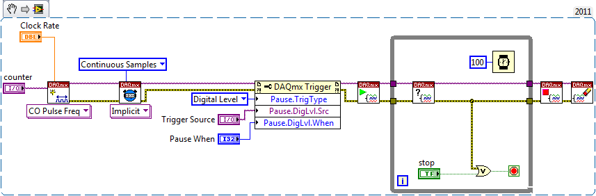
Continually acquire analog input, internal clock, break, Multiple device
I have a PXI chassis with 6 cards SMU-6363. I want to acquire data on the channels of each SMU-6363 map continuous AI, using the internal clock for timing. I need to use a trigger to pause reading of a DI on one of the cards SMU-6363 for a break and to reactivate the acquisition. I came across this example: https://decibel.ni.com/content/docs/DOC-12256/ , but keep getting error-201019 DAQmx start task "trigger break is not supported in a task to more devices. To configure the start of break in a multi-device configuration, you must use no more than one device per task and route manually clock in demand signals. »
The problem is that the configuration of I is made during execution by the operator. Sometimes they want to acquire data on one HERE through all 6 cards SMU-6363, sometimes they want to acquire data on each channel of AI through all 6 cards SMU-6363. What makes the task definition until manually route clock signals between devices for each rather difficult task.
Is there a simpler way to solve this problem?
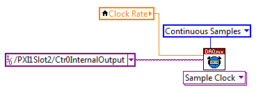
Set a task to output counter - something like this:
Next, configure your task of analog input to use the sample clock output of the meter:
Best regards
-
NI USB - 6259 BNC DAQ: analog input signal cross on the question
Hello
I use the NI USB-6259 BNC DAQ unit to acquire a four-channel analog signal, and I'm having a problem with a signal that affect others. The circuit, I am running is:
I have a wire connected to a battery (two AA batteries at ~1.5V), which then feeds the signal cable to a BNC cable, which feeds an analog BNC of data acquisition channel. The field of NBC feeds to another wire, which is attached to a conductive plate. The idea is this: when I touch the wire connected to the battery for the metal plate, I complete the circuit and thus get a binary not anything at all about 3V. When I tested with an osciloscope using two channels (each earth connection to the metal plate) I get independent steps whenever I touch any of the sons of the respective batteries to the metal plate (i.e. it works as expected). However, when I use it with data acquisition, whenever I touch a wire, I get a response in all other channels (3 others), even if their respective sons does not touch the metal plate.
No one knows why this happens, and how I might be able to stop this 'cross-talk '?
Thank you
Veritas
I see, and you're right. This request will have trouble with crosstalk. Luckily the ground channel thing should help you.
Configure your DAQ to collect twice as many channels as you need. Connect your wires in the odd channels and short circuit (ground) the entries of those even.
Now when you scan the channels it will always technically crosstalk, but it will come from a channel to the ground so that there will be nothing to interfere with your measurements.
At least that's the theory.

-
Acquisition of IMAQdx - synchronization problems
Hi all
I built a code a VI in which I put in place a camera IMAQdx acquisition in a loop of producer-consumer (see attached VI). The code also controls the camera exposure time.
I would like to record images at 10 frames per second, the camera is set up to acquire NI Max 10 fps, but surprisingly, the code saves more than 10 frames per second, even if I inserted a synchronization feature in the loop of the producer.
Any ideas on what does not work?
Thank you.
Kind regards
E.S.
There are three modes of acquisition of the camera: Snap, sequence and Grab based on parameters that you set:
Wink (single image acquisition): continuous = 0; Buffer Count = 1
Sequence (fixed number of frames): continuous = 0; County of buffer > 1
Enter (Continuous Acquisition): Continuous = 1; County of buffer > 1
- So I guess you want continuous acquisition, which means that you must set the buffer has more than 1 (usually more than 3) that the driver uses internally to avoid overwriting images.
-You can check The Grab and configuration example VI attributes that lets the user view the current attributes and settings, update the attribute parameters, acquire images continuously and display images in an image control.
-From the example above, you can also see the framerate that acquire and then proceed to the backup of images.
-To access the example help-> find examples--> search for Grab.
-
medium-sized images of the camera with IMAQdx
Hello
I need through the images acquisition of a camera and subtract the average of an acquisition of background image.
Although I use an ethernet connection, the program is REALLY slow.
I'm new with Labview so any suggestions is very welcome... I have attached the program
This is not my best work, but take a look a this. The same code acquires the two images, you just choose what image control stores the updated average image. the Analyze button then processes what is in control of the two images (reference and absolute).
Your problem is that you initialize constantly every time as an image. Just do it once.
-
analog and digital data synchronization
Hi all
I would like to help with what I seek to accomplish, if you don't mind much.
I'm trying to synchronize the acquisition of analog and digital modes using a common trigger that launches both types of data collection at the same time. What I've done so far, is wasting his time trying different combinations to gather examples of LabVIEW 2011 on the synchronization of data - namely the 'Multi-multifunction-Synch AI lu Dig Chan.vi' and 'Multi-Device Synch-Analog Input-Finite Acq-Analog Start.vi.
I tried to combine the two, because one contains digital and analog, the other contains the trigger for multiple tasks.
I guess I should place the trigger (either digital or analog-eventually I will want to choose) then call the "Get Terminal name with device Prefix.vi. But from there I'm not sure wheter to connect the name of the terminal of the sample clock digital channel or a digital leading edge of the digital chain trigger.
Also, the way it is wired now I get errors at the local terminal name, so I don't know exactly where this terminal must come from.
I try my best, I could use a little help, I have attached my attempt with the examples that I speak to you.
Thank you.
Hi beefcake.
The CtrInternalOutput internal output line is used as sample for your digital output sample clock source clock. If you change the settings for your CO Pulse Time is Dev1 and your digital output is Dev2, you will notice that the name of the product terminal would give Dev2/CtrInternalOutput. So what you get here, it's as well as the digital output device sees his sample clock, instead of the clock itself.
If you just want to use a digital/analog input as your trigger, you should do something more as in the example above. Do you use multiple devices, or are all your lines on the same device? This example is more complicated because it is synchronization of signals on several devices.
Looking at how this VI is wired, you can see that the digital signal triggers the analog signal. You want the analogue signal must be started first, so that when the digital signal triggers the analog task is already running and can trigger immediately. If the digital task started first, it can trigger until the similar task had started, and they do not exactly trigger at the same time.
I hope that clarifies things. Kind regards
Maybe you are looking for
-
25.0 Firefox for Linux 64 - x 86 is more judge Flashplayer
I had to update Firefox manually to 25.0 21.0, because he told me that it was up-to-date. probably a problem with all versions x 86-64 versions of Linux and not i386. I also updated to the new x 86-64 Linux Flashplayer (2013-08-20 V11.2.202.310) and
-
HP DesignJet T120: Hp Designjet T120 editor blank posters printing
I have a client who is trying to print posters made in Microsoft Publisher for this printer, but whenever it goes to print, the pages are completely empty. Although the test pages are works very well. Any suggestions?
-
Are the current models for sale on Lenovo web site "WWAN Ready"? By that I mean that they include the housing of SIM card and antenna WWAN and are simply missing the WWAN modem card? I am interested to buy one now and then add the WWAN card later. Th
-
Convert binary data into data across the
Hello If I got DAQmx Read.VI binary data (analog 2D I16 Nchan Nsamp), how can I convert these data to scale? Best, Jay
-
Oracle of the MAF error ' cannot read the DataControl uses on loadDataControl for the id:
Need help!I created a simple SOAP web service for a remote database that works very well in 12 c WebLogic Server and also in the Jdeveloper HTTP Analyzer. When I use the same web service in the attached code, I get the following error (I've included