Acquisition of Digital Data Output: generate a pulse with a specific width (depending on time)
How can I generate a digital pulse with a specific width? I was not able to find examples online. Thank you!
With the USB-6000 - essentially none. He has only digital software programmed according to i/o. on your system, you may be able to generate impulses at speeds up to a few hundred Hertz, but there will be a considerable amount of timing jitter. Tens of milliseconds can be common and even longer variations may occur occasionally.
Please indicate which are the times for your impulses, so someone may be able to provide recommendations specific to your needs.
Lynn
Tags: NI Software
Similar Questions
-
I want to integrate the ANSI C sample program ReadDigPort - ExtClk.c in my own big package.
I want to use the internal clock of the BNC NI USB-6259 (.. 80 kHz 120 kHz).
In the document:
High speed M: Series Multifunction DAQ for USB - 16-bit, up to 1.25 MECH built-in BNC connectivity. / s,.
is written:
Or sample DI source clock: Any PFI, RTSI, HAVE sample or convert clock, AO, Ctr n out internal and many other signals sample clock
The digital subsystem doesn't have its own dedicated internal synchronization engine. Therefore, a sample clock must be provided another subsystem on the device or from an external source.How can I use internal clock case OR USB - 6259 BNC for the acquisition of digital data in my own big software?
With what other subsystem on the device can generate a source of the clock? How?It is possible to set a clock on an internal counter (for example ' Dev1/ctr0"):
Creates channels to generate digital impulses that define the freq and dutyCycle and adds the channel of the task that you specify with taskHandle.
DAQmxCreateCOPulseChanFreq (taskHandle, "Dev1/ctr0" units, clockName, idleState,
initialDelay, freq, the duty cycle); worksBut it is not possible to drive this internal clock to a terminal (for example "/ PFI0/Dev1"):
DAQmxErrChk (DAQmxCreateCOPulseChanFreq (taskHandle, "/ PFI0/Dev1", clockName, units, idleState, '))
initialDelay, freq, the duty cycle); does not work: error DAQmx: measurements: type I/O of the physical channel does not match the type of I/O required for the virtual channel you create. Name of the physical channel: PFI0. Name of the virtual channel: clockThe sample clock source can be derived from an external terminal (for example "/ PFI0/Dev1"):
Sets the source of the sample clock, the sample clock rate and the number of samples to acquire or generate.
DAQmxCfgSampClkTiming (taskHandle, "/ PFI0/Dev1", maximumExpectedSamplingRate, DAQmx_Val_Rising, ")
DAQmx_Val_ContSamps, bufferSize); works. Acquire or generate samples until you stop the taskBut it is not possible to derive the internal counter of the clock (for example ' Dev1/ctr0"):
DAQmxCfgSampClkTiming (taskHandle, "Dev1/ctr0", maximumExpectedSamplingRate, DAQmx_Val_Rising,
DAQmx_Val_ContSamps, bufferSize); does not work. Error: Acquire or generate samples until you stop the task: make sure that the name of the terminal is valid for the specified device. See Measurement & Automation explore valid names of terminals. Property: Property of DAQmx_SampClk_Src: DAQmx_SampClk_ActiveEdgeSource device: Terminal Source Dev1: Dev1/ctr0Hi datafriend,
using what it says is correct:
Or sample DI source clock: Any PFI, RTSI, HAVE sample or convert clock, AO, Ctr n out internal and many other signals sample clock
The digital subsystem doesn't have its own dedicated internal synchronization engine. Therefore, a sample clock must be provided another subsystem on the device or from an external source.This means that if you do not use an external signal as clock you can use the sample clock to HAVE it on board or at the output of the internal counter.
There are also 2 ANSI C examples in this regard:
http://zone.NI.com/DevZone/CDA/EPD/p/ID/4485
http://zone.NI.com/DevZone/CDA/EPD/p/ID/4488
So in both cases you have to use a fictitious task you need only for the generation of the internal clock (HAVE or CTR)
-
Scrambled data LPMS GENERATING-B sensor with Bluetooth
Hello
I'm working on a program of live-stream the LPMS GENERATING B-accelerometer, gyroscope and the magnetometer. (http://www.lp-research.com/9-axis-imu-with-bluetooth-wireless-connectivity/)
So far I managed to connect the sensor and to obtain its data. However, the data are very blurred.
Is there a way to decode scrambled data, or I'm doing something wrong with the release of the data from the sensor?
Please find attached a scrambled data image and I use the VI
Thank you!
From the manual, it looks like data is passed as hex then do a right click on the indicator and select hexadecimal display.
-
How to generate a pulse with the signal generator?
Hello
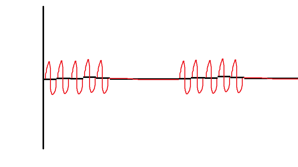
I would like to ask if anyone knows how to use the Elvis platform to generate a regulated pulse wave?
It should look roughly like the picture above. A sine wave with the regulation.
Anyone who can answer my question please respond to my post.
Thank you.
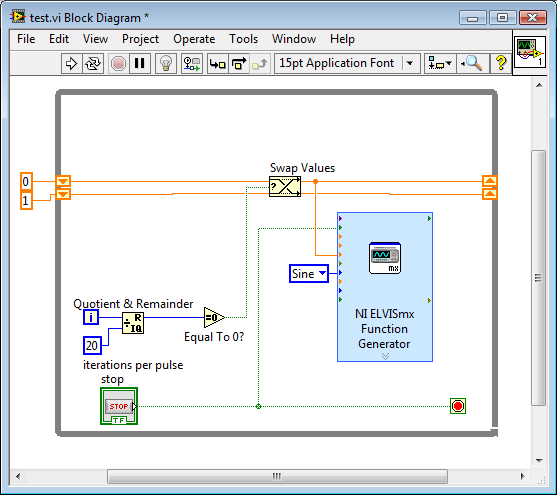
You are using LabVIEW to generate the waveform or using the Soft front panels? In LabVIEW, you can use the express VI generator function and specify the Type as "Sine". Then, simply change the amplitude of the sine wave. During the actual pulse, the amplitude would be what you want (i.e. 1 V) and while the pulse is idle, set the amplitude to 0.
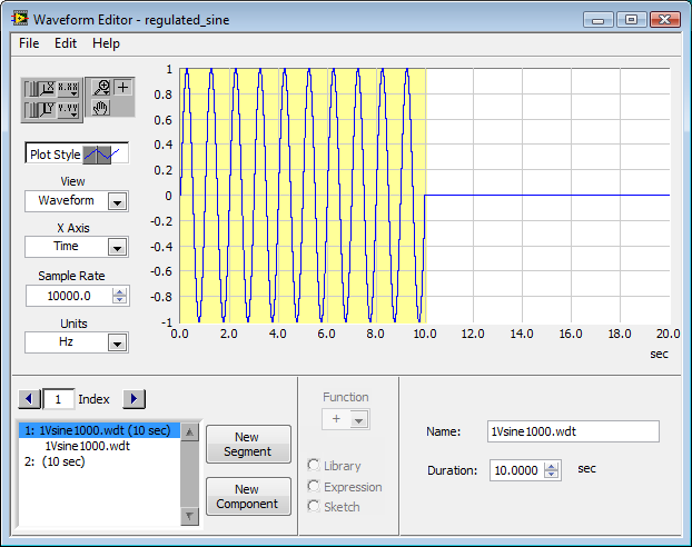
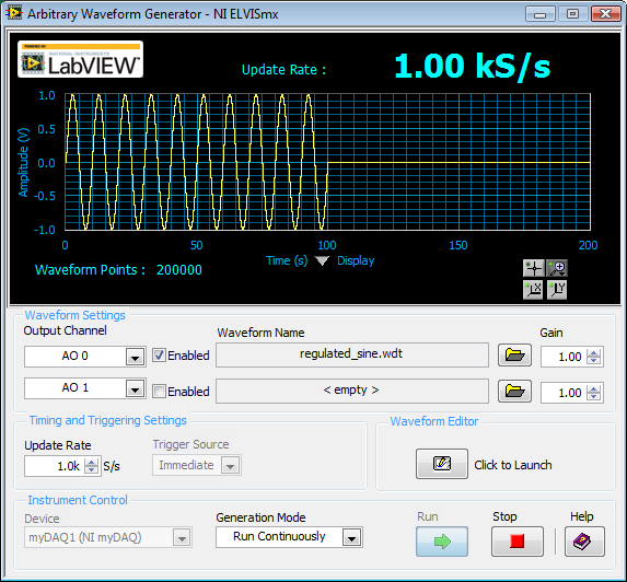
If you use the soft front panels, you can use the Waveform Editor to create a waveform that includes a sine wave for the length of your pulse and then the values of '0' for the rest of the time. Then use this waveform in the flexible front of the arbitrary signal generator. Simply create a component of sine as the first part of the wave and then add another element to a level DC '0' for the rest.
-
SSRS 2012 export to CSV with no data by generating coma separated with an empty value
I have a report that have no data due to parameter motor (both have true noheader configuration).
In SSRS 2005 its generate empty csv file and for SSRS 2012 his record still generate with coma and an empty value, something like this:
,,,,
Those that were generated by Server (SSRS 2005 and 2012 SSRS), tnot different heres in the rsreportserver.config file to make segment.
If I exported the csv file to SQL Server Data Tools for Visual Studio 2012, it generated an empty file (which is correct).
Anything I missed here?
Just realized, its due to my 2012 SSRS is the RTM version and its due to SSRS bugs has been fixed on SP2 + CU3
https://support.Microsoft.com/en-us/KB/3002049
-
How can I determine what digital data was issued last with the regeneration?
Is there a way to determine the last digital data output if you are running a quick revival and regeneration? Right now I use a digital channel not used by the channel with the same clock that I use for other data capture. It works very well and I know that the data I receive are correct, but there is something wrong with burning a channel for that. The data I am regenerating changes several times during the trial for counting samples to determine where I was in the buffer would make my code more complex and the chances of a mistake to increase.
I have a mixture of material that I use for a cDAQ-9172, a box of series M and a PXI-1033 USB.
Hello Tom,
There is absolutely something wrong with having to use one of your channels to monitor what you're out, however, it's the best we can right now. The problem is, when you set a buffer until the release, the access card to this memory stream location it will regulate. It's speed leaving and overall card design. There is no way back on the material for do what you are looking for and no software to interact directly with the location of the buffer.
-
How can I more easily generate a pulse of digital output of finite length?
Hello
I need to open and close the two pneumatic valves using a TTL output (without load current or the output power) using a PCI-6280 or PCI-6601. The valves must open almost simultaneously and closing after different amounts of time elapsed (millisecond level timing, maybe 100 microseconds-level timing at worst). My current plan is as follows:
-Create a task with two digital outputs (type of waveform) and another task with a counter that generates a frequency set by the user (I know I can use the generator frequencies on one of these cards, but I would have preferred a counter - the best selection of frequencies).
-Wire the output of the counter at the entrance to clock two digital outputs.
-Output of the meter is digitally triggered by another digital channel which I use to control if the pulse goes out. Through its counter node, it is programmed to be redeclenchables.
-Two digital waveforms are drafted who have both consist of unique active high pulse (i.e. signals go ' down (for the amount of time user-defined) - low ".")
-These signals is written to their respective ports and their tasks have started, as is the task of the meter.
-Whenever the user wants to open taps, digital triggering is sent up and then back to low (this can be done with synchronization software, because it is not exactly when the fire valves). Whenever the user wants the valves open for a different period, different digital waveforms are generated and written in the buffers of the digital output channels.
My problem is that it looks like a lot of effort for me to go and I wonder if there is a much simpler solution, that I don't know everything. You can program a computer to produce a pulse of finite length? Is there a faster way to program a digital output for that channel?
Thanks to anyone who responds to their help.
It is certainly instructive. Thank you.
The thing is, I have only six total counters to work with and I have a lot of time to do things. To use these solutions, I would need to use 4 or 6 account counters required to my needs.also that I would need to synchronize their departures.
Overall, I stick to my method for now - less system resources and synchronization can be don by using the same meter of finished output clock and not to use a trigger to all.
Once again, thank you for your help so far.
-
I need to generate 3.3 V logic level Digital train of pulses with the NI PCI-6221. Can I change the level of 6221 OR logic output?
The output cannot be changed. 5V to 3, 3V level controllers are readily available (Maxim, I think). As long as the scanning speed (etc.) is fast enough for your pulse train, even 3, 3V regulator would work. I don't know if NEITHER offers a module to condition TTL levels.
-
I hope someone can point me in the right direction and also to clarify some concepts!
Background: I am currently using the box USB-6009 and labview on a laptop to output 2 analog waves. It acts as a waveform(0.5-2Hz) of speed (periodic) for an engine step by step (with a driver) to execute a loop of traffic, and the other waveform acts as a signal short 5V to trigger some imaging equipment. The ability to move or to delay the start time of the wave of 'trigger' compared to the waveform of speed in steps of hail (ms) became a requirement for my experiments. Given the time where the USB-6009 case, software based accuracy was not good enough because I need, and the way I wrote the VI limits my delay/travel at the speed of wave deltaT(30-40ms). I started to look at the USB - M series (portability is an obligation) since some have calendar based on the material, and I could send the signal to a buffer rather than iteratively having read every value of the wave in. It also seems that a digital short "pulse" works better than an analog wave form creating any. Where I ran into some confusion is to determine the requirements of a deterministic way sync the two. I am looking for new hardware. I started by looking at the box USB-6211. However, I ran across a few posts talking about the digital I/o correlated being required to perform vaguely similar configurations, which would require something more like the USB-6221. Since I have probably to the digital output to be on a time scale different analog output, is i/o digital correlated required? If not, would the 6211 work?
Just to be clear, I need the periodic waveform and relaxation to be constantly in phase (anywhere, 10 minutes to several hours). Then be able to move the pulse +/-1ms (minimum) and repeat. I can justify the most expensive device if necessary, but I don't want to get something I don't need.
I have attached a figure (not not to scale) of what I am after, in the likely event that my explanation was not too clear.
Thank you
Gabe
Hi Gabe,
The 6211 did not buffer IO digital as some of our other devices. However, there are two complete meters on the 6211 which can be used to perform a generation of pulses (pulse or continuous pulse train - you can output a pulse train using two counters finished). You can take a look at the section Applications of meter output x 621 manual for more information.
What it sounds like, the 6211 will do what you need for the following reasons:
1. the AO of the 6211 lines are buffered and can be clocked up to 250 kHz per channel (in contrast to the 6009 using AO NI by SW).
2 the 6211 counters can be used to generate two pulse based on a basis of time of 80 MHz (12.5 ns pulse width and resolution time). The 6009 does not output meter.
(a) if the two pulses must be on the same line, you must configure a task of generation of pulses finished' (this example uses two meters behind the scenes).
(b) if both impulses are on separate lines, then you can use a task to counter separated for each line with a different initial delay.
The 6211 does not supported clocked generation of digital signals (e.g. 100010101110100) but if you just need to generate impulses so that's precisely what the counters can be used to. I think that's where all the confusion, but seems like the generation of digital signals should not be necessary for your application. Trigger the counter outputs out of the trigger to start AO and adjusting the parameter 'Initial period' should give you what you are looking for. Don't forget to start the tasks of meter in the software before the tasks of the AO (if they are armed and ready to go before the start AO is sent).
I hope this helps, don't forget to post if you have any questions!
Best regards
-
DAQ USB 6363 - generate digital data series through the single DIO line
Hello
I'm new with Labview, currently, I bought NI DAQ USB 6363 for generating control signals and signals analog accquire. I would like to send digital data series through one of the digital IOs with throughput of 30 kbps. Please see the attachment for the data frame. Could someone comment the feasibility of this? Y at - it codes for the example that I can refer to? Most of the examples I've looked at so far deals to generate several line instead of 1 single line. How can I achieve this?
Thank you
Diem
Hey diem.
After looking on your code, I understand what you were trying to do. Here's how I'd do. Usually we do not write code to clients, but you peaked my curiosity of! I hope this helps. Good luck!
~ kgarrett
-
Using CC of Muse, I want to generate a survey in order to process digital data.
Hi all
Very new to web design and Muse. I'm currently looking through tutorials for basic usage.
My question is, can I generate a survey that will collect digital data based on questions such as:
"How many times a week do you...." »
I so want the data to be processed based on the parameters and weightings etc. which I stated, and gives the user a rating based on their responses.
This kind of thing is possible in the Muse? Or do I need a design software web based code?
See you soon
James.
Hi James
Yes it is possible if you host your site with Business Catalyst.
Web Forms can be used to collect data with custom fields, and then you can filter using the generation of reports.
Data collection and rating submitted data are 2 separate process, for example, I have a field in my booking form "how many seats" and boxes option to select numbers. This process will allow to save user data submitted. On another page, I have a blog/forum where user submits its history and then people can comment on, and note the element, which is a separate process.
Both can be carried out on the end of BC.
and in case you want to all the functions to be put on the same form, you must use Web applications, with which it is possible.
For example, I create a web application and an application form for comments and same time I configure to display presentations on my web page where viewers can rate/comment on submissions.
Please go through these documents for more details:
http://helpx.Adobe.com/business-catalyst/using/create-insert-form.html
http://helpx.Adobe.com/business-catalyst/partner/add-Forum.html
http://helpx.Adobe.com/business-catalyst/using/add-blog.html
http://helpx.Adobe.com/business-catalyst/partner/Web-apps-module-create-custom.html
Thank you
Sanjit
-
Generation of digital signals through external trigger pulse on PCI 6251
Sir I want by NI 6251 because I read it has the ability to generate and acquire digital signals on port 0. I want to know that can I generate external clock wave triggering (providing impulses to a line on the acquisition of data)?
Hi Ali211,
Yes, you can use a source of sample for the digital input/output clock external clock. You can connect the external clock source to one of the lines PFI (PFI0-PFI15) and specify the source clock sample like this outer line of PFI.
There are some shipping DAQmx examples that you can start with. Find the examples by clicking Help > find examples in LabVIEW.
DAQmx continually reading digital channel with External Clock
DAQmx channel External digital writing Clock
Hope this helps.
Chris G
-
static/digital waveform output and low frequency measurement of voltage - SMU-6358
Hello
1. I have an attached VI [digital_voltage_output] who must generate a logical true or false static state in the output of the device/port0/line1 Word to say. When the VI works I click the button several times, but nothing happens to the port0/lines1.
2 such a thing [digital_voltage_waveform_output_square] if I'm trying to generate a digital waveform to pin the same with the waveform generating VI. If I connect a waveform chart to the output of the generator function VI, then the chart will show me the good waveform I want, but still nothing is written to the text file.
3. I have read the manual for the X series cards, but it remains unclear for me a little how to things of the road in LV I have a measure of the frequency measurement VI low frequency that I downloaded. It offers me the ports for the supply frequency - ctr0, 1, 2, etc. As far as I'm concerned the PFI ports are responsible for these types of actions. How can I find out the LV that I want to connect say ctr0 and pfi0? »
I use LV 8.6.
Thank you
Kriváň
Hi Kriváň,
The problem you had with the choice of a specific digital line as a physical channel, is that the control that was previously used in this example was created for a data acquisition task that uses a whole port rather than a specific line. I was able to overcome this problem by removing the control and recreate. The control now gives you the option to choose the specific digital lines e.g. port0/PXI1Slot2/$line0.
I was also able to overcome the error of-200802 you mentioned. I was able to do this in a real constant of wiring at the entrance to auto-start the VI DAQmx writing then remove the DAQmx beginning the subsequent code VI. The modified code is attached.
I hope this helps.
Best regards
Christian Hartshorne
NIUK
-
Generate the train of pulses with counters
Hello
IAM using PCI6023E data acquisition in labview 7.0. I need to generate a continuous 5 kHz 1usec pulse train and I have exhausted my two counter/timers. Can someone proposes how to generate a pulse train without using timers? I/O maybe?
Thanks in advance
HV
voh720 wrote:
Yes, I have outputs analog left. Can analog get the kind of resolution that I mentioned?
Thank you
According to the specifications, the 6023 has not all analog outpts. Quite difficult to use what you don't have.
-
How can I specify a delay generates a pulse meter?
Hi all
I have a question on the use of the meter to generate the pulse train. I did not how to program but I try the test panel in MAX and I see that it generates pulse train to certain rates and with a pulse duration. I think if it is possible to generate only a single pulse with given the duration of the impulse to sometimes after I start the job? I have a code to generate an analogue waveform, waveform of 35ms. I wonder if it is possible to synchronize the output of the analog waveform and counter such to 12.5ms after that the output waveform has started, I send this unique pulse from the meter port on. I have no idea how to do that, I think to use a delay but it is difficult to accurately control the time exactly 12.5ms.
Well, assuming DAQmx_Val_Low for the resting State, fires the meter will wait the initial delay and then generate a pulse at the time you request. Little time is not actually used in this example simple impulse.
From what you described, you must add a trigger to start your task of meter output (DAQmxCfgDigEdgeStartTrig) to you can set the meter to trigger off the beginning of analog output trigger. Set the initial delay on the counter for 12.5 ms. Start the task of counter in front of the task of the analog output. You should get your pulse 12.5 ms after you have started the task of the AO.
Best regards
Maybe you are looking for
-
490 error code when you try to install service pack 2 with vista
I have service pack 1 installed on my computer but I get an error message when you try to install service pack 2
-
You can use a HP 2500 CM on a home network printer
I try to install my HP 2500 CM on my home network instead of using from the LPT1 port to a single computer. It is equipped with a Jetdirect J4100a card. Is it possible to attach it in the LAN router so that I can use it on other computers in the Hous
-
Windows 7 Edition home premium download sony vaio
I have laptop sony vaio VPCSB16FG series. Without knowing it, I formatted the C drive and I lost all my backups. I wanted to download the windows 7 Home premium for sony vaio since I was the real key. How can I download operating system. Its 64-bit
-
I have set up a cisco 861 as a vpn server. Could I help you if someone can tell what is the problem? Clients can connect, but cannot access local resources from lan for subnet 10.0.10.0 Building configuration... Current configuration: 9770 bytes!vers
-
Impossible to select and move the letters while playing 'Word with friends' through facebook
Original title: play games During playback "words with friends" through face book... I can't select and move the letters on the touch screen without the screen, scrolling up and down.I need the touch screen to allow the movement of the letters c A C