acquisition of voltage compactRIO 9025
Hello world
I just got a new compactRIO 9014, I plugged a tension to the channel 0 of the series C 9205 with differential input card (pin 1 + and pin 20-). I get the ok on the front panel voltage, but if I drag the other channels on the same module in the block diagram, I read the same value of voltage on these channels I have no input voltage connected. I wonder what is the origin of this
I also of integrating acceleration of problem I get ok from 9234 on compactRIO c series card. I tried to use integral.vi and point to point full x (t). I don't seem to get good results for speed. Using the same card 9234 via my USB connection with the traditional DAQ assistant, get the speed by integrating ok.
I'm only using module time real 3.5.1 for my application. I do not wish to use FPGA.
I'd be happy to help with this
Jide
First-, you should consider using the cRIO Waveform reference library for your FPGA, this will release most of the 9014 for analysis:
http://sine.NI.com/NIPs/CDs/view/p/lang/en/NID/209114
Second, you should consider the following Sound and Vibration Measurement for your vibration analysis routines. We have optimized the measures to work embedded in CompactRIO
http://zone.NI.com/DevZone/CDA/tut/p/ID/12196
Here are some of the tools of audio measurement and vibration
http://www.NI.com/soundandvibration/software.htm#software
Tags: NI Hardware
Similar Questions
-
Signal acquisition of voltage AC using NI 9206 9205 and cRIO
Hello. I have difficulties accurately acquire a signal voltage AC using a module OR 9206 and cRIO. I'm looking to acquire signals of tension of the two types of current transformers Magnelab: divide the rope and the base. In Labview, I first fill out an array of size 2 500 with the signal of the sensor (DIFF mode), and then calculate the RMS of the table. For the core of split CTs, I'm able to acquire exactly reading the correct voltage (verified by measuring the match on the line using a power Analyzer Fluke 434 amp. For the CT string, however, using the same method of table/RMS, I am unable to gain precisely the correct voltage reading. Measure the amp on the line using the Fluke 434 PA, good the CT string tension should be 0.05v. Using the 9206 (DIFF mode), the RMS of the array gives a reading of 0.071 voltage. Now the interesting part is when I measure the voltage by using two different True RMS DMM, I get two different readings. A multimeter, a Klein CL2000, reads the voltage in 0.05v. Other multi meter, a Fluke 189 reads wrong to 0.071, the same that I get using LabView and NI 9206 release. I guess the question is how the Klein interprets the signal differently Fluke 189 and the NI 9206 via LabView module. A difference between the split-core and rope CTs, is that the rope CTs require a power external power supply 12-30 v AC or DC. I'm providing 12v DC. I tried several AC and DC voltages and still get the same wrong result. I am quite sure that it is not a question of power supply, although perhaps the integrator in the rope is the creation of a single signal. Any ideas? I appreciate any input.
Thank you
J.Grant
AK2DM:
Update - found solution
-
Acquisition of the voltage with the NI 9206 module
Hello
I use a module NI 9206 with a CRIO-9081 to get 14 acquisition of voltage from 0.4V to 5.8V using the mode of CSR.
Then I plug the 14 to the module of the AI0 of entry I 15. When I connect the first 12 pins, I get the good acquisition but when I connect the two last pole, the tension of the first two (pin AI0 and AI8) traditionally of 0.4V and that's what I don't understand.
I tried to remove the two first entry, but then the two following voltage increase of 0.4V.
That's why I wonder if I forgot something, why the first entry increase and if someone already has mett something similar.
Tahnk you

Sounds like you see a form of ghost for me.
-
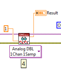
Measure the voltage and the temperature simultaneously with PCI-6281
Measure the voltage and the temperature at the same time at the same time. However, when I put the voltage and temperature in a loop, the acquisition of voltage is significantly delayed. When I put the voltage and temperature in two different loop, none of them works. There is an example in aid of Labview as shown. This structure works fairly quickly? In addition, how a volgate get and temperature Analog DBL 1Chan 1Samp? I check the exported excel, the first column is 0, 1 the second column contains the value of the voltage, temperature value. I wonder how can I get these two values for each scan.
,
Assuming that the DAQ cards can handle it, you can set an analog trigger for the channel of the tension. Then you just X samples to get your 100us data value. Keep the last sample.
-
Data acquisition and video acquisition
Hi all
I am a new user of Labview. I am trying to build a VI that synchronize acquisition DAQ voltage of one or more channels to an AVI video acquisition (IMAQ) (including a bayer encoding process), recorderd by a digital camera.
I built this VI which I attach.
The problem I have right now is that I am able to do a video and a signal, but the duration of the video is always different from the signal, I can read the time in the file LVM vector.
Could you please tell me how I can solve this problem?
Perhaps this question may seem easy, but. As a new user, I know very well how to use Labview in the most effective way.
Thank you all for your time.
Emanuele
Thank you very much, I am modifying the program, but I do not understand how you linked the son two error, I can't find the box you put just before the other 'error' box, please let me know hat it's and what is used.
Thank you very much four alos your patience.
Emanuele
-
NOR-USB 9229: How audio signal acquisition?
Hello
It's one of those stupid beginner questions
I use a module OR 9229 USB to capture the audio output of my computer line as follows:-left line-out goes to AI0 +.
-right line output goes to AI1 +.
-land line out of is divided into two and goes to AI0 - and AI1 -.
What is the correct way of wiring?
In case it is, I have (I think) have problems audio signal acquisition. In the Measurement & Automation Explore, I creates a task for the acquisition of voltage AI0 (44100 Hz, etc.) -nothing is displayed on the graph when I run the task! (I have music running on the computer during the measurement) Otherwise, the 9229 flashes green, seems to be ok, auto test work, etc..
Someone has an idea what I am doing wrong?
Thank you!
Hi acgrama,
That sounds like it should give you a signal any (not an empty graph or a flat line at 0 V), but the USB-9229 is not very suitable for audio:
- The USB-9229 to entry level is of +/-60 V. A line level audio signal will use a small fraction of that. Of the USB-9229 precision and plug noise are adequate for your application?
- The USB-9229 can't acquire them exactly 44.1 kech. / s. It supports some 50 kech sampling frequencies. / s divided by a number between 1 and 31, as 50 kech. / s, 25 kech. / s, 16.7 kech. / s and so on. When you specify a sampling clock DAQmx not taking in charge, he is forced to the top supported next, which in this case is 50 kech. / s. (you can read back the SampClk.Rate property to see what DAQmx forced the rate to.) For 44.1 kHz audio to USB-9229, you will need to re - sample the acquired data (which are specific to the programming environment).
Assuming that you're just trying to do it for learning or experimentation, here are a few ideas:
- Is the line connector configured as an output line? Many mothers today have reassignables audio connectors.
- The volume of the source (wave, CD, whatever) high enough?
- On the graph, is scaling auto turned on? If you display data in a table instead, are the numbers exactly 0 or any close?
- The output of the line works if you are connecting to another device that is designed to handle signals to line level?
- If you connect a battery (AA, 9V, whatever) for the USB-9229 instead, read the Max supply voltage?
Brad
-
Problem of reliability data acquisition PXI-4071
Hello
I'm having a problem of reliability using my 4071 Pxi digitizer mode.
I have a number of tests that use the SMU-6363 (usually configured for DC) analog output to provide a stimulus for our own device, which has a number of a/d converters. We use the PXI system for calibration and testing.
1. I select a voltage ranging from tensions.
2. program the PXI-6363 to drive this tension
3 TIME about 10ms to settle. Note there no discrete capacitors or resistors in the circuit. Everything is parasitic and would generally be under the nF mark and less than 10 ohms
3. configure and Initiate() acquisition of data with the PXI-4071. In general, I use a sample rate of 1000 s/s and get about 30 samples (worth 30 ms). Activation is immediate and I used the default a queue time, 0, set the time and it doesn't seem to make a difference.
4. measure the voltage with the CDA. For debugging purposes I have sometimes made twice once before calling Initiate() and once after. The after is normal. The time required to measure the ADC is shorter than the acquisition time, but regardless of stimulation by the SMU-6363 is constant
5. extract the waveform.
6. the average waveform and compare the value of ADC measured by applying tolerances etc.
Here's the problem: it works well most of the time. But only 0.1% of the time (1 on an acquisition of 1000), I get 8-12 samples that are close to 0. It sounds like a problem of time settling (on the surface), but no matter the amount of wait time data, I always get this behavior. Not only that, but the tension before the call to Initiate() in height CDA, it always confirms that the motor voltage is already set to the programmed value. Nevertheless the acquisition presents near data 0.
So far our independent ADC always reports the expected before and during acquisition (100%) voltage. It's like the DMM input is disconnected during the acquisition during a period of time, because we have confirmed that the voltage is already present prior to the acquisition (component can). I have no errors the insider or FetchWaveForm calls. I still have all my samples. And 99.9% of the time that everything works as expected.
The DMM and ADC are connected to the same point and both are referenced to ground, and as I said before only the parasitic capacitance and resistance (cable). We use a matrix of switching (PXI-2530 (b) to make these connections. We almost always use 51/2 digits and 10V range for data acquisition.
Hello
I thought about it and was going to repost but am distracted.
The device with the ADC also has a mux and switches the mux to an internal node. It only switches when measuring and is open at other times. There is a race condition where the acquisition starts too early and maintains the acquisition after that the switch is open. Unfortunately I don't have the option to trigger.
I forgot the internal mux that I had designed the test years ago and I did some updates to improve the stability of the test. That's why we start the ADC measurement when acquiring.
I just added a routine to reject samples below a threshold
-
My computer recognizes my cRIO-9002 but not the analog input NI 9205
Hello
I work with a unit 9002 cRIO and a NI 9205-analog inputs. When I check if my computer recognizes cRIO in Measurement & Automation Explorer, everything is OK, I have the cRIO with all its software and ports.
But when I am using the wizard DAQ in LabVIEW, I click on "data acquisition-> entries-> voltage->...» "and he said:"no supported device found ".
I searched through the forum, I installed all the new versions of the software and drivers, and I tried with real-time or labView with nothing.
Do you know where is the problem?
Thank you!
Hi xavgu
You won't be able to use the DAQ Assistant to acquire the data of your cRIO. Try to do is like trying to flyfish with a bottle opener, which is totally different things.
To get data in the cRIO you must first program the FPGA to read data in the module and then transmit data to the real time controller, which can either logg data or send it in turn via TCP/IP to you Windows host. Unfortunately the 9002 cannot manage Mode Scan, which would have made it easier for you.
Please take a look at these links:
Getting Started with CompactRIO and LabVIEW
Getting Started With LabVIEW FPGA 8.x
Best regards
David
NISW
-
Wrong time file Express with NI9361 medium Freq dynamics of the signal
I have an interesting problem with recoding of the frequency to a file with SignalExpress measures and a NI9361. I was able to find a workaround, but here's the question:
As in the attached SignalExpress project, I'm analog acquisition of voltage using a NI9234. In this case, the module is in place only for the/cDAQsim/I/SampleClock channel exist for my next step to reference. I'm also acquisition of previous frequency with the NI9361 in dynamic mode with an average using the reference to external clock of the analog input stage. Then I have a backup at the ASCII stage where I want to write a file leave ASCII, comma with absolute time.
That's the problem. In this case, I cared only to save the frequency to the file. But, when I did the absolute time would count per second for 100 points, then loop back at once and County place again. (See attached Test01.csv.) This is the same behavior that if I tried to record data using just the NI9361 without an external sample clock.
If instead, the save operation I take FIRST entry then the frequency I will get a file with the correct absolute time as Test02.csv analog, attached. Even if I save the frequency as the first entry and then return to tension the problem at the time scale.
Anyone know why that would happen? Is there a simpler way for the frequency measures stamped recored with the NI9361 and SignalExpress without analog data recording? without using an analog input module at all?
Hello
This question looks better suited for the Signal Express community forum page. Please ask your question here.
Thank you
-
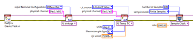
NEITHER 9870 on 9144 using EtherCAT: unsupported?
Hello
I have a Setup very similar to that illustrated in this post. That is to say:
. A CompactRIO 9025 (instead of the target of industrial controller)
. A chassis 9144 connected for CompactRIO with EtherCAT
. A NI 9870 plugged on the 9144
The post linked above seems to imply that this setting could work. However, when I add the C Series modules to the 9144 I get an error message saying something like "the 9870 is not supported by this version of the industrial communications for EtherCAT driver.
. I use version 2.5 of the EtherCAT driver that seems to be the latest version.
. Other modules are recognized correctly, some of them with a warning in case I want to use the SCAN mode (but I didn't). A NI 9213, for example.
. Two modules from a 3 rd-party seller where it is.
. Move the NI 9870 for CompactRIO itself is not an option, it is full as an egg.
Any suggestion is welcome.
DLB
-
Application using Signal Express RTSI
Hello
I am interested in recording of analog signal synchronization (start time, acquisition of the sample, 3 cards PCI-6289 stop time) and possibly their synchronization with 3 to 5 more cards NI PXI-6221, that are connected to the same host PC via a PCIe-8361 interface PXI-8360. For now, I will focus on the 3 cards PCI-6289. I used a RTSI cable with VI recorder is no longer supported and guess that it works well with Signal Express. I've set up a device cable RTSI NOR able & Automation, which includes 3 PCI cards. 3 PCI cards are the only devices connected to the RTSI cable. When you check the properties of the RTSI cable device, I left all the boxes unchecked, that seems to be the right setting for my application. In Signal Express, when you add a device in the Panel on the left of data acquisition (analog voltage signals), I always see each individual card (Dev1, Dev2, Dev3, etc.), but there is no device RTSI. If I look into the advanced features of synchronization of each of the three panels DAQAcquire, I can apparently use a card as a master clock and the two other cards will have master card sync signals (is it automatically via the RTSI cable, or do I need to connect external clock out on the master card to the clock on the slave cards?) but once again There is no mention of the cable RTSI, or configuration of device RTSI in MAX. Using the clock of a card in a situation of master/slave help, but it starts and stops all three cards at the same time, or no apparent synchronization between maps will simply be a coincidence?
Any suggestions are appreciated.
Kind regards
Brian
You really need your question to the SignalExpress Commission. Few people here use it.
-
How can I write snapshot of my data to the file measured every 5 seconds
Hello
I try to take a snapshot of my stream once every 5 seconds and write it to a. File LVM. I have problems with the VI "write to a measurement file. The pace at which it writes data to the file seems to be dictated by the 'Samples to Read' parameter in the DAQ assistant. I tried placing the VI 'Write in a file measure' within a business structure and the launch of the structure to deal with a "time up" VI. As a result only in a delay of 5 seconds before the insiders 'Write in a file as' VI. Once the VI 'Write in a file as' is launched, it starts writing at 20 x per second. Is there a way to change it or dictate how fast the exicutes VI 'Write in a file measure'?
My reason for slowing down the write speed are, 1) reduce space occupied by my data file. (2) reduce the cycles of CPU use and disk access.
The reason why I can't increase the value of 'Samples to Read' in the DAQ Assistant (to match my requirement to write data), it's that my VI will start to Miss events and triggers.
I don't know I can't be the only person who needs high-frequency data acquisition and low-frequency writing data on the disk? However, I see a straight road to key in before that.
The equipment I use is a NI USB DAQ 6008, data acquisition analog voltage to 100 Hz.
Thanks in advance for your help
See you soon
Kim
Dohhh!
The re - set feature has not been put in time elapsed VI!
Thank you very much!
See you soon
Kim
-
Newbie - waveform graph axis graduation issue
Hi all
I'm new to studio of measure (v8.0 with .net c# 2005) sorry if this question has been answered 10 times more, please feel free to point me to a previous thread.
I have a request to:
drive voltage analog sampling at 10 Hz reading 1 sample per tick.
standard waveform graph axis X and Y and a plot as a collection of doubles.
So far, it's something pretty simple and I can get all this work in the code example.
My problem is that I want for my X axis to read between 0 and 1800 with the major divisions of 100 and minor divisions = 50. I would like for my actual graph however contain 10-point increments, so that would mean that there will be 500 points between each minor division.
I looked down through the properties of the axis and I can't enough find the properties that I need to set.
Can someone help me please.
Thanks in advance.
Steve
Hi Jamie.
Thanks for the reply. I spent all the update yesterday my system of measurement studio 2012 + Dev Studio 2010.
I put these settings, looking more closely at my data, I have a problem with my data acquisition analog voltage so I'll search through my solution and start a new thread, as I'm getting 3 times more data that I need, so it is causing my chart to be wrong.
Thanks again.
Steve
-
Hai
adxl330 accelerometer is compatible with dac-usb6008, usb6009, usb6221, usb6229, compaqdac. Could someone please help me wid this...
What do you mean by "compatible". An accelerometer (even the one you mention) simply generates a differential voltage based on acceleration, so almost none of the DAQ devices will work. The real question is to know if you need software or calendar based on the material for your acquisition of voltage and this will have an impact on what hardware DAQ for. How many times do you need to read the tensions? What is your sampling rate? What you do with values? These affect what DAQ device for more real accelerometer. I would say from here: to start with OR-DAQmx: Home Page
-
NOR USB6210, problem to trigger on a PowerPlay with measurement and automation
Hello
I use Labview version NIDAqmx 8.7 driver version 8.5.1,, Measurement & Automation explorer 4.4.1 and a device OR USB6210.
I create a task with Measurement & Automation to make an acquisition of voltage on the AI0 channel.
I want to use the function of digital triggering with the channel PFI0. I connect a signal square on the AI0, and PFI0 channels. I put the edge on the RISE, for example. When I make several acquisitions, and I notice on the curve that the USB6210 device does not fire correctly, sometimes used trigger edge is on the RISE and sometimes FALL.
Could you help me? Is it a driver problem?...
Thanks in advance, Daniel.
OK, nice to hear that everything works as expected.
Good luck,
Maybe you are looking for
-
I have problems with the App Store, when Ive reset the password already, but still no change, I made sure everything was up-to-date of security/account wise as well. Help, please
-
I removed the check mark to "Accept cookies from sites" in the Privacy tab, but when I restart Firefox the check mark is back! This problem started with version 3.6 and so I upgraded to version 5, but the problem remains. Any suggestions?
-
Laptop Toshiba computers have serial port (COMM.)?
Hello Is it true that Satellite phones have no serial port COMM? I am very surprised by this. All others is OK, but I need COMM port. Maybe I should buy another Toshiba notebook? Ivan
-
How do I know all of origin built into my HP HW?
I have a HP Pavilion dv7 Notebook, PN FV807EA #UUW. I installed a new operating system: Windows7 Ultimate, I had a lot of trouble with the previous version (a HP service person installed a beta version of the operating system by mistake and I learned
-
Get ' High Definition Audio Driver Package - KB835221 [WXP]. "
For stupid reasons to list, I uninstalled the so-called 'High Definition Audio Driver Package - KB835221 [WXP]' using Add/Remove programs of Control Panel under Win XP utility. So now (DUHH!) none of my audio works. I searched the site for a replacem