Agilent a54845a scope configuration
Hi all
I am configuring the Agilent 54845 a scope in LabView. I installed the necessary driver (hhttp://sine.ni.com/apps/utf8/niid_web_display.download_page?p_id_guid=E3B19B3E9118659CE034080020E74861) and placed the instrument on LAN. Successfully NI MAX sees the instrument, and I can send commands to the range through the NI VISA test.
When I try the test "put hp54xx started.vi" LabVIEW present with the driver, then problems arise. I put the correct entry of the IVI (the name of scope recognized by NI MAX) successfully but I can't set option string (the VI runs only in Simulation = 1 mode); If I try to put the Simulation = 0, I get different types of errors, such as:
1073807339 error has occurred hp548xx read Waveform.vi
Possible reasons:
Driver status: (Hex 0xBFFF0015) timeout expired before the operation is complete.
Otherwise, same with the predefined settings:
1074135024 error has occurred in hp548xx configuration Channel.vi
Possible reasons:
Driver status: (Hex 0xBFFA0010) invalid value for the parameter or property.
Secondary error: (Hex 0xBFFC0003) parameter 3 out of reach, or an error occurred when setting setting 3.
Development: range
Am I facing some known problems? Can it be linked to the fact that I connect via LAN, while the pilot only mentions GPIB?
Thanks in advance.
The alternatives are to write your own driver or make changes to existing ones. The others are very viable if you have an understanding of the manual instrument and LabVIEW experience. The query id in the initialize function is a simple string comparison. Have you even looked at the block diagram?
Tags: NI Software
Similar Questions
-
Agilent 33500 B configuration of duty cycle
I use the function generator to Agilent/Keysigt 33511 B to produce a square wave with offset, amplitude and frequency specified. However, I'm unable to set the duty cycle. Is there a VI to control this setting?
Hi jmountney
If you use this driver , I think that there is a function named .vi configures signals Standard Advanced (square) and it has an entry for the duty Cycle, so I think this could help you.
-
Hi all
I would order the generator functions, using Agilent 33220 attached A vi. But it takes a Subvi as bellowed. Once I tried to ignore these Subvi, it displays an error. I would like to generate the waveform of the place at 20 kHz, 20% duty cycle, range from 2.5 to 3.0 V. can I get help? Please, consult are Subvi.
Loading:
: \Agilent Series\Public\Action-Status\Enable Output.vi 33XXX Loading:
: \Agilent Series\Public\Close.vi 33XXX Loading:
: \Agilent Series\Public\Initialize.vi 33XXX Loading:
: \Agilent Series\Public\Configure\Configure Waveform.vi Standard 33XXX Thank you.
Let's be more specific. Use the driver found here:http://sine.ni.com/apps/utf8/niid_web_display.download_page?p_id_guid=0470714759413BCCE0440003BA7CCD.... As Jeff said, unzip the contents of
\instr.lib. -
While with PXI-5122 digitizer loop counter
Hello world
I am a beginner of products NOR. Currently I use the PXI-5122, 2014 Labview for the ultrasonic signals. I have a problem when you count the number of signals using an external trigger (by a function generator) source. When I trigger the digitizer under 50 Hz, the meter is working properly (a single trigger = a signal). With a frequency greater than 50 Hz of trigger, the meter is malfunctioning. For example, with the shutter to 50 Hz and 500 number of signals, the counter takes 10s to get data. But, with the trigger of 100 Hz and 500 number of signals, the acquisition time was always around 10 s.
You can see the code in the file attachment.Please let me know if you have any suggestions or recommendations for my situation, I would appriciate that.
Thanks in advance!
Best regards
YouWorldALoneMe,
Looking at your code, you're software re - trigger your device. With your Setup, you configure the digitizer to hold a single record acquisition in your "A - Scan.vi". This VI opens the resource OR-SCOPE, configure, captures, returns the data, then closes the resource OR-SCOPE. It then does this for each unique A-Scan that you do and would be the reason that b Scan.vi takes so long. It appears then that fewer than 50 Hz, this reset any software and reconfiguration and the acquisition can occur without missing a trigger, but more than that, your triggers occur faster it takes to do these things.
What you need to do set up the digitizer to a multi-record acquisition. This is done using the 'niSCope configure horizontal timing.vi' and wiring in a number higher than '1' in the entry "number of records". "You can find an example of how to perform a multi-record acquisition if you open the Finder of example OR > material input and output > Modular Instruments > NOR-SCOPE > Getting Started > niScope EX Multi Record.vi.
In this example, the digitizer is only once configured, and it returns all the documents requested at the same time. For your application, each record would be a simple Scan of A, and then if you configure 500 files, your B-Scan would be 500 wide. This time allows the material to rearm between triggers that is much faster to do it in software.
For a verification of more complex example out (in the finder of the example) "niScope EX Multi record go get more available Memory.vi"
Kind regards
Nathan P.
-
Selection extended DHCP and several VLANs
I have a switch that has 2 VLANS: vlan 2 and vlan 3 - and both computers are connected to the switch where each PC is a member of one of VLAN.
PC2 = VLAN2
PC3 = VLAN3
The switch is connected to a router that acts as a DHCP server with several 3 DHCP scopes for each of VLAN, basically a simple configuration "router on a stick". This question has been confusing me for some time: How does the router knows what dhcp scope to assign an IP address to a particular computer?
Let's say PC2 is now trying to get an IP address from the DHCP server, I know initially that he will send a DHCP DISCOVER broadcast to the router message and I assume that the router will know the VLAN demand coming as well based on the information contained in the package. But how the router discerns what scope to assign IP address to PC2 especially if I need PC2 to have an IP address in the subnet 192.168.2.0 and NOT 192.168.3.0 or vice versa? The controls of such a choice?
IP dhcp pool vlan1
DHCP excluded-address IP 192.168.2.1 192.168.2.10
DHCP excluded-address IP 192.168.3.1 192.168.3.10
!
IP dhcp pool vlan2
network 192.168.2.0 255.255.255.0
test.com domain name
Server DNS 192.168.2.1
default router 192.168.2.1!
IP dhcp pool vlan3
network 192.168.3.0 255.255.255.0
test.com domain name
Server DNS 192.168.2.1
default router 192.168.3.1THX sc.
Hi Sherwin,
It's will be very simple. I guess that on the router configuration stick will have something like below.
FAS int 0/0.2
encapsulation dot1q 2
IP 192.168.2.1 255.255.255.0
FAS int 0/0.3
encapsulation dot1q 3
address 192.168.3.1 IP 255.255.255.0
Now when a PC that is connected to the VLAN 2 send a DHCP broadcast this program is received by the interface that belongs to the same broadcast domain (VLAN 2). This broadcast is received by the Fas 0/0.2 and this has encapsulation dot1q sub interface 2 and so it will be part of the same broadcast domain (VLAN 2). If the router will search if there is no DHCP scope configured for the ip range on the interface sub Fas 0/0, 2. Now, router knows the 192.168.2.0 extended DHCP and assign the IP range of this scope to any PC in the VLAN2.
I hope this helps.
Concerning
Najaf
Please rate when there is place or useful!
-
Scope Agilent MSO6104A and IVI steps
Hello
I use scope Agilent MSO6104A that is connected via Gbspecifications FOR.
I would like to control the scope by following the steps in TestStand IVI (TestStand 4.2).
I have downloaded the driver 'IVI - COM, IVI - C Version for 5000, 6000, 7000, 546xx 1.3.20.0 series Oscilloscopes' of the Agilent site and installed.
Agilent IO executable is installed as well.
The logical name of the instrument is created in MAX.
Then, I tried to communicate with the scope by TestStand IVI markets.
I copied the scope of the steps of the sequence of the example.
IVI step with the 'Init' operation tools works very well.
But the IVI measures fail.
For example, 'Configure 1 channel' fails with the following runtime error:
Details:
An exception has occurred the call "RunStep" in "ISubstep" of "ZNIUGOL of Types of step TestStand Ivi"
An error occurred during the execution of the step.
Error of component control works IVI: IVI configure failed for logical name 'MS06104A '.
Details: IO error: %1. [IVI. Error Code: BFFA4214]
Source: TSIviStepTypesError code:
-32032; User-defined error code.
NEITHER spy errors also (see the attachment).
Thanks in advance
I think you might have more luck if you use the pilot of the IVI-C written by NOR.
-
Configure the second channel of TDS 2012 scope
Howdy,
Our laboratory has recently acquired a range of Tektronix TDS2012 dual channel and I'm getting so he can play nice with Labview 8.5. I downloaded the plug-and-play drivers and the accompanying screw sample without problem. I connected the scope via a GPIB-USB-HS adapter. PC running Win2k.
The screws of the sample and some of my creations seem to be great with the exception of a question to work. I can't for the life of me get the vertical scale on the second channel to do what I want. When I use "Example VI" of the driver and set the Volts/Div to anything for a reading of CH2, changes the CH1 setting (?), it does indeed read CH2. I can't find where I could adjust the parameters of CH2 regardless... the vi "Set up display" seems to be independent channel.
Any thoughts?
Kind regards
Matt Pausley
North Carolina State University
Hi Matt,
I just downloaded the Tektronix TDS 200 1000 2000 project series Style Driver of instruments here, and there is no screws with the word "vertical" in them. To make sure that you use the style of the project pilot, go to C:\Program NIUninstaller Instruments\LabVIEW 8.5\instr.lib\Tektronix TDS 200 1000 2000 series and confirm that there is a file of Tektronix TDS 200 1000 2000 Series.lvproj it and that the screws are in folders, not a Bachelor's degree in law. The VI that you will use to configure the vertical range is Set up Channel.VI. Pay close attention to the VI and control documentation.
See you soon,.
NathanT
-
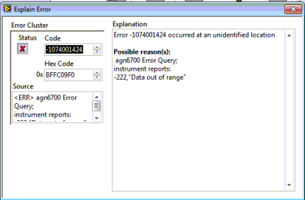
Agilent N6702A - error in the configuration of Channel 4
Hi guys,.
I use Agilent N6700 LabVIEW drivers for the configuration of the instrument. I am able to set up the first whithout 3 channels any problem, but when I try to configure the Channel 4, he throws and error - 222 "" Data Out Of Range '. " I am able to configure Channel 4 physcally on the instrument, but not of LabVIEW.
All the world is facing this problem?
Any help would be appreciated.
Kind regards
NitzHey guys,.
I thought kind of the issue myself. Channel 4 was grouped with channel 3, in which case, only the lower layer (ch3) is configurable which inturn will set up the group. Missed me the point that I found in the data sheet.
Thank you all who have looked into this post and tried to help him.
Kind regards
Amine31 -
Hi all
I'm having trouble getting my Agilent U2356A configured correctly for my application. My task is simple: measure 10 samples at 100 Hz on Channel 101. I want the differential mode, unipolar (0 - 5V). I checked my connections using the Agilent measurement tool, but when I try to acquire data with LabVIEW I do not get the right voltage.
Here are the settings I use:
Defeat
 CAN (@101)
ROUT: CHAN
 OL UNIP, (@101)
ROUT: CHAN: RANG 5, (@101)
ROUT: CHAN
TYP DIFF, (@101)ACQ
ISO 10ACQ
RAT 100Any suggestions?
I spoke to a support of Agilent person and we have solved the problem. I was "unflattening" as U16 instead of I16, who threw the conversion.
-
Agilent E5070B: error when using 'configure calibration VI.
a mistake came during the communications test LAN to the Analyzer of Agilent E5070B network with the "agena Configuration Application Example.vi".
It seems to me that there is a bug in "agena Configure Calibration.vi" that is called during the execution of the example of vi.
In my case, it helped change the string declaration of impedance with the declaration of the decimal point:
old: :SENS:CORR:IMP %lf
new: %.;:SENS:CORR:IMP %lf
Can anyone tell if this problem is really a problem for all users?
(or only for users with the German country settings because it is obiously a problem with the statement of the decimal point)
It is probably a very common problem in all the countries that do not use a decimal separator. I know many deselect the option "Use localized comma" instead of rewriting the pilot.
-
Configure 6513 JOINT and has no local SCOPE
Hi, my version of IOS catalyst 6513 is 12.2 (18) SXF16 and 12.2 (33) SXI5, today I want to configure my JOINT module.
Should I COVER my traffic vlan for the JOINT, right?
commands like:
monitor the session 4 source vlan 21
monitor the data-port of destination 4 intrusion-detection-module 10 session 1
But the switch tell me:
Local % Session limit has been exceeded
So, what should I do if I want my JOINT work.
Thank you!
Hello
You satisfy VACL to pass traffic to the IDSM2. VACL capture allows you to specify a VLAN you would like to have the IDSM2 follow.
So if you know what VLAN from the etherchannels, then you can include them in the VACL configuration
For example:
intrusion detection module 4-port data 1 capture allowed vlan 10-20, 40, 70
Please find documentation to configure VACL 6500 switch:
http://www.Cisco.com/en/us/docs/security/IPS/6.1/Configuration/Guide/CLI/cli_idsm2.html#wp1030767
Hope that answers your query.
Cyril Shankar
-
Configuration of FlexSync for the Agile plm for process 6.1.1.1.11
Here are the two queries that we have:
1. create a new report on the environment:
We followed the procedure to create a new flexsync report below:
- Open the configuration of FlexSync on the application server.
- Copy an existing out of integrated report "SingleFormulaPER".
- Change the new copied the report in step 2 and provided a name and traveled to the model file that had to be added.
- Committed change.
To approve the changes, we observed that the database entry is made in the table FlexReportFields and FlexReports for the new report that we created.
After doing this, we've made an entry for the plan of the site - Extensions.xml for the menu item. We are not able to see the name of the new report created in the user interface on the specification of Formulation. It says "no translation is lblbatchsheet. How to build a PKID for the entry in the CommonXLAExtensionCacheItem table and add the question of translation for this new report?
What are the steps to follow to get this entry available for the user to be able to generate reports?
2. adding a field to the report:
We have modified an existing template to add a new column of the effective Date of the Summary tab. We used the name as "Summary.Effective" in the name Manager in excel for this new attribute template.
After the update the model, we will open the FlexsyncConfig to edit the report, look for the updated model and then commit the changes.
After that make us this change to the model, when we run the report specification formulation, we are able to see this column added to the report but the value is not getting from the report.
We found that there is no entry in the FlexReportFields for this new attribute changes. When that we export this report to the FlexSyncConfig SQL code to run the script on database, as we are unable to find this entry in the script.
These are the fields that must be added to the exiating report:
Attribute
Spec
Tab
Section
Density (2 values, 2 unit of MEASURE)
(Exit formula) material referenced
Summary
Design features
Starting on (date)
Formula
Summary
Summary
(Known to contain) allergens
(Exit formula) material referenced
Compliance
Allergens / known to contain
What are the steps that must be followed to modify an existing template to add/remove fields?
Using FlexSyncConfig report, in the table fields Editor, if you the si vous la souris mouse click the column of fields on a single line.
channels section manager updated to display the Manager string associated with this field. You can then use the
Manager string the drop down menu to choose what string to associate with the field.
-
oscilloscope to Agilent 3000 series - no communication
Hello!
Recently, we bought an Agilent MSOX - 3014 (2000-3000 series) A oscilloscope.
PROBLEM: Does not WORK with LabVIEW.
DESCRIPTION: The scope has been connected via USB to a PC computer and has been successfully detected by the system and LabVIEW and installed in the system. OR MAX says that the device is connected and working properly but it doesn't.
After you run a sample VI (acquire waveform) comes with plug-ins (project style) driver, the scope is set back to the factory setting and after a while, the connection is cut and there is no effect (no waveform on the screen). After this very simple procedure, the scope is not responsible for the material side (no response to buttons, etc.). The complete communication history was captured with NI IO-TRACE and I attach the saved file.Tested system configurations
(tested on two different computers with the same result)
LabVIEW 2010 32-bit
LabVIEW 2011 32 and 64 bit
Win 7 Pro x 64 (English version)
VISA - most recentI'm looking forward for your help
THX!
MJ
-
Running El Capitan, the Configurator 1.7.2 update won't go away
I just upgraded to El Capitan, and I was using Configurator 1.7.2 previously. An update so that it is available, but this version is not compatible with El Capitan. I installed the new configurator version 2, but it is still in the list of updates. How can I make it disappear?
Please, open a search window by pressing the command-F key combination in the Finder. Select the Mac as the scope of research and the search for the app in question by name. Delete all obsolete copies that you find.
-
The NI PCI-5124 scope with 2 triggers
Hello
I would like to ask about the trigger for starting and reference with PCI-5124.
I found a sample VI on the following link, but it does not work as I expected.
http://zone.NI.com/DevZone/CDA/EPD/p/ID/2998
VI 'start_and_reference_trigger.vi' can detect the outbreak starting and reference in my system, and they begin data acquisition.
He starts data acquisition when both start and reference triggers are entered.
However, what I would do is:
1. sampling at 200 MHz with a 1500 with a single channel record length.
2. receive the signal to start (i.e. 50 Hz)
3 receive the reference signal (i.e. 50 kHz)
4. for each trigger reference, I would like to acquire the data, i.e. data of 1500 for each 100 trigger acquisition reference (not with the combination with the shutter release to start)
Start trigger: _|^|_________________________________________
Ref trigger:______|__|__|__|__|__|__|__|__|__|__|__|__|__|__|____
^ ^ ^ ^ ^ ^ ^ ^ ^ ^ ^ ^ ^ ^
hours of relaxing I want to acquire
Trigger channels I use are:
Start the trigger: PFI 0
Trigger for Ref: PFI 1
With the sample VI 'start_and... '. ", I found that it acquires when the two begin and trigger reference comes and data collection was only after the release of a single reference.
I hope my explanation is understandable and I can have a solution soon.
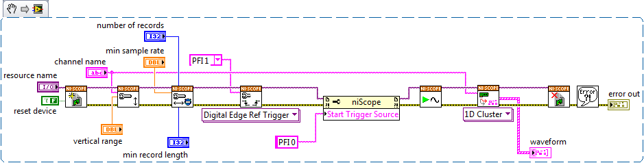
Hi Tom,
This example configures a trigger starting and reference, but only for a single record. It is inside a loop, so it will continue to require a trigger start and each record. According to your description of the problem, you want to make an acquisition standard multi-record of 100 records, but you want to implement a trigger to start at the beginning of the acquisition. "' To do this, you can simply open the example of shipping"niScope EX Multi Record.vi"found in the example Finder LabVIEW or by browsing in your Start menu programs" National Instruments "NOR-SCOPE ' example. You need to add the property node to define your Trigger source begin to be PFI 0, but other than that, it should work fine. I have advanced and created a simplified with the trigger Start implemented, attached below. I hope this helps!
Maybe you are looking for
-
Yesterday, I got a message that I "could not mail" because my Inbox was full and that I should delete some files or compact. He had only about 20 messages in there, but I had ignored the suggestions that I have compact for awhile I went to the menu a
-
My mouse cursor is sometimes a plus sign, not an arrow
Is anyone having a problem with their cursor on the computer screen appear as a sign, when you use the mouse? In a text document, it is the traditional vertical bar. When I move the cursor on the computer, it may be an arrow, but then turns into a
-
Satellite L500-207 will not find wireless networks
My laptop cannot identify wireless networks at all and I don't know how to fix it. Everything works fine and I'm aware wireless is turned on and anti-virus scans were clean. First of all, the problem occurred after I have reset default DNS for the DN
-
Uninstall the pre-installed HP games
Hello My question is, If I uninstall all games preinstalled on my laptop HP dv7 will it also uninstall Microsoft games too. I want to uninstall the HP games because I don't play them a lot, and those I've played have now is more free time left. I loo
-
Hello world I understand that mainly El Capitan is reported as for most of Yosemite, with performance improvements. However, I just bought a new MacBook Air, OS X Yosemite (10.10.5) with 256 GB & 4 GB RAM and I don't know if would be a good idea to u