PCI-6111 valid sampling frequencies
We have old card PCI-6111 that we still use. A question was posed regarding the applicable sampling frequency setting.
According to the manual, this thing must have base clock of 20 MHz and 100 kHz. There also a divisor of 24-bit and (not sure about this) multiplier of 2 bits. I guess that these can be used for the base of appropriate clock frequency scaling.
What sampling rate can be set on this thing? This is a spec 5 of average size, then that would be the upper limit. Can I put any arbitrary frequency (integer) under this? Or what I need to work explicitly what it's capable of? With a 24-bit divider, this would imply that there is a wide range of frequencies that doesn't "work" on this map.
What happens when I select a frequency that is "bad"? Round it inflicts, turn down?
Hello Isaac, it's Paul with engineering Applications to the OR.
This device offeres 2 at simultaneous sampling of the analog inputs, 5 MS/s per channel - The 2 AI can enjoy up to 5 Mhz per channel each. You can only have 1 frequency clock for your tasks to HAVE, but this clock frequency can be adjusted from 1 kHz to 5 Mhz, set by you. Note that most of our maps allow GOT down to 1 HZ, but this ADC is different because it uses a pipeline ADC convereter. In addition, since this card can taste at the same time, it means that two analog channels will be read at the same exact time (in parallel). In addition, the value of I is a 12-bit number.
Tags: NI Hardware
Similar Questions
-
limited on PCI-6052E sampling frequency
I'm trying to measure with two channels with a PC containing a NI PCI-6052E card that is capable of 333KS/s on LabView 8.2. With two channels each channel must be able to 333KS/s / 2 = 166.5KS / s. everytime I try to set the sampling frequency above 94339 Hz I the following warning and the vi no longer works.
WARNING 200012 occurred DAQmx start Task.vi:1
Possible reasons:
Clock speed specified is greater than the maximum ADC conversion rate. ADC invaded errors are likely.If I place a similar task in the Measument and Automation Explorer and I can easily make two channels measures to 160kHz without error. Above 166kHz I start getting the same caveat (200012). The code that I use calls first DAQmx create Channel.vi, then DAQmx Timing.vi and finally DAQmx start Task.vi. Everything works fine and I did measuements, but I can't rise above 94339 Hz sampling rate even if it should be possible.
I just looked and I can't understand the issue here.
Dear Voyn,
I thank very you much for your message on our forum. If you create a task for a single channel, you can get a higher sampling rate? Are you able to reproduce the same problem with an example from the finder example? Go to hardware to go end tab selected and output-DAQmx online-online-online-online Acq Cont voltage analog measures & chart voltage-Int Clk.vi
You can select several channels as well. If it shows the same behavior; which driver DAQmx do you use?
Best regards
-
The pci-6111 can capture samples 400 000
I'm just a signal that lasts 8 seconds. The signal varies from 20 kHz to 25 kHz, so I would probably sample right around 50 kHz? At that note, and if I wanted to capture the whole 8 seconds, according to me, that it would take me about 400000 samples. Is there a way that this can be done with the card PCI-6111. FYI, I'm using LabVIEW 7.1. Thank you.
-
Problems with timing of analog input PCI-6111
I'm reading the analog input of a PCI-6111, who receives a square signal of 1 KHz with a cycle of 50%. I put the sampling frequency to 1 MHz and wait until the data points are 1 usec outside. When I check the signals received, it appears that the duration of each period of the square wave is 1.22ms instead of the expected 1.0 ms.
The following is a snippet of what I tried:
int NUM_SAMP = 10000;
DAQmxCreateTask("",&mTaskHandle);DAQmxCreateAIVoltageChan (mTaskHandle,
"(/Dev1/AI0","",DAQmx_Val_Cfg_Default,-10.,10.,DAQmx_Val_Volts,null); "
DAQmxCfgSampClkTiming(mTaskHandle,"",1000000,DAQmx_Val_Rising,DAQmx_Val_ContSamps,NUM_SAMP);
DAQmxReadAnalogF64(mTaskHandle,NUM_SAMP,10.0,DAQmx_Val_GroupByScanNumber,mDataBuf,NUM_SAMP,&numRead,);
Can you tell me what I am doing wrong?
Hello SNL_NB_1167,
A good place to watch code you know works would be the finder of the example. "" "" Open the finder example and navigate to hardware input & output "DAQmx" analog measures ' tension ' ContAcq - IntClk.prj
Run this code and see if you get the same results. If so, then we would know that it's a hardware problem and not a problem with the programming. If you see the correct behavior, then you have code that you can shape your out of. I hope this helps.
-
Problem with a precision of analog input on PCI-6111
Hello
I'm reading an analogue signal which varies from 0-11 V using a card of acquisition data PCI-6111. The signal comes from a Tube set (PMT) which is part of a microscope configuration, so it is very important that the resolution of the analog input signal be as wide as possible generate quality images. According to the data sheet for the PCI-6111, the analog input resolution is 12 bits, which should correspond to a sensitivity of ~2.686 mV for my voltage range.
To test this, I set up a task to analog input with a 0-11 V voltage range to read samples of an analog output, which I wrote a simple waveform. Since the 16-bit analog output resolution that I assumed that it would not limit the accuracy of this measurement. I have attached the VI I used for this measurement below. The analog input data are saved not truncated in a text file.
Analyzing these data, I found that the real input sensitivity is ~9.766 mV, corresponding to levels of voltage exactly 1126,4 and ~ 10 bits.
Is there a reason why the resolution of analog input is much lower that it is indicated on the card? What are some of the ways I could improve the sensitivity of this measure?
Best,
Keith
Sorry, when you mentioned the specs, I thought you already had them. If this did not come with your Board of Directors?
-
High speed continuous measurement of encoder with sampling frequency of 1 kHz
I am able at all times the position of a linear encoder using a PCI-6602 counter card, and I need to know how to set up so that the counter rotating at high speed, but the data is inserted into the buffer at a frequency of 1 kHz. I am able suddenly to a hydraulic cylinder, and I am not concerned about the event recording to high frequency except to the extent where they throw off the number considerably if the equipment does not run fast enough to detect all the impulses of the encoder.
Now, I think is that the external sample clock signal control (routed internal pulse output counter) time rate whereby the equipment detects the impulses of the encoder and the rate at which it inserts data into the buffer. With a pulse 100 per inch encoder and a sampling frequency of 1 kHz, the extended final position of the cylinder is turned off by +/-0.15 inches, which is unacceptable.
I need calculate a speed of this information, so I prefer not to use software timed sampling to control this (it's more difficult programming for other reasons as well - several asynchronous measures). Any ideas on how to configure the hardware to count faster than the speed at which she inserts counties in the buffer?
OK, you're clearly on the right track here, so I will focus on some details.
1. How do you know that the +/-0.15 "differences are * measurement error rather than * error of movement? Why wouldn't be an accurate measure and a proposal which can vary slightly from the nominal value?
2. I wonder some all electric noise and defects that may produce false edges. The fact that the behavior was better by using a sampling rate limited (200 kHz) in the digital inputs may be that some of these flaws were so short that they were never captured.
I did a ton of work with the Commission to 6602 encoder and I can certainly confirm that count equipment is sensitive to the edges in a few tens of MHz. (I know its 80 MHz for edge counting, but I think I remember that it can be of the order of 20 to 40 MHz to accommodate the time of signal propagation extra of the quadrature decoding circuit).
A small point of clarification. You're talking about the speed at which the meter "works to. The value of count is a register whose value is changed completely by the circuit, * independent * of the sampling frequency. If you enjoy with material-clocked County in memory buffer or interrogation of software without buffer not a bit for circuits that increments / decrements the value of the counter register. (In other words, I am completely convinced that you would get commensurate with position end even if you took only 1 sample software-polled after the end of the move instead of sampling at 1 kHz all the way through.)
So, if the value of the counter is disabled, it is because the circuit detects producers of County of the edges that shouldn't be there. Something you can try is to set up digital debounce filter for input lines of the PFI corresponding to the encoder Source inputs and to the.
-Kevin P.
-
Sampling frequency of adjustment for the analog output of sine
Hello
I tried to do something very simple: using an analog output card PCI 6221 to produce a frequency 50 Hz sine curve. For this I used a Vi to create a curve sinus and different screws DAQmx. But I have trouble understanding the principle of virtual channel and I think I do an error of adjustment of the sampling frequency and number of samples: once for the vi, second time sine "DAQmx - synchronization. Can I use the same values for both of these screws?
On my oscilloscope, with frequency = 50 Hz and the sampling frequency = 1 kHz, I get a null signal. Then according to two values, I'm differently evaluated signals. For example, with f = 1 Hz and sr = 10 kHz, a frequency 0.7 Hz sinus.
Make sure that the start for the analog input task occurs after the analog output. By plugging in the wrong thread to an analogue output start task first, and then to the start task, you guarantee that the AI cannot start until after the startup of the AO.
-
I have a system with a map of the 9234 compactDAQ 4 Groove and a 9401 in slot 5.
I use a function generator to create a 5V square wave frequency sweep.
The frequency of scans from 1 Hz to 10 Hz in 3 seconds.
I have this tee in my door to counter 0 (PFI1 - 16 Pin) and an analog input channel 0.
In LabView, I do a period measure counter that has a trigger defined on the trigger to start ArmStart HAVE.
Piecemeal the signal into two channels, I see the time counter correspond to zero-level positive slope crossings in the data to HAVE it.
By the presence of a square with a mutation frequency wave, I know for sure that the time is not out of a period.
I noticed the downturn to take samples, the greatest moment of the synchronization error.
Here is the data that I have saved:
sampling rate 1 / (sync error times)
51200 1250
25600 625
10240 256
2048 51.8
1651 37
It worked of Y = 0,0244 X + 1.1262 with R ^ 2 = 1.0
So it could be, I have a programming error, or that there is a bug in the hardware or the base software.
Thanks for any help to understand this question.
BTW, I use this system to make an analysis program in the stopped vehicle with direct sequence over time - of course analysis based on the revolutions. I found that order analytical tools was not flexible enough for what I had done, so I started from the ground upward.
Hi Greg,.
Looks like you see the entry delay the NI 9234 (Group delay). As specified in the instructions for use NI 9234, entry delay is equal to 38.4 / fs + 3.2us. This is because of how the sigma delta ADC works - after the start, it must acquire a certain number of samples before returning the first valid sample. This delay is expected.
Here is a knowledge base on the subject. There are a lot more, just do a search of the knowledge base for "group delay.
-
How to acquire with NiScope at different sampling frequencies and lengths Records?
I need to acquire the data of 2 channels of the NI PXI-5114 map two different sampling frequencies high, at the same time. Also, I put 2 different record length. Is this possible?
I understand that 'Vertical' settings can be configured for individual chains because the function 'Vertical niScope Configure' has 'channels of entry with which we can assign the desired channel. But for horizontal settings such as "min sampling rate" and the record min length, I could not find such an option to specify the channel. Would it not common to both channels?
I hope that the device is capable of simultaneous sampling and therefore channels can be configured individually to different sampling rate.
Hi AJ_CS,
Why do you have to be distinct from sampling frequencies on channels separated from the digitizer even? What different sampling rate do you want?
But for horizontal settings such as "min sampling rate" and the record min length, I could not find such an option to specify the channel. Would it not common to both channels?
You do not have an option to configure the settings of hoirizontal on a channel by channel basis because this concept does not exist in the traditional sense of the use of a scope. Compatible with the concept of IVI, an oscilloscope traditional benchtop will have only a button or a set of buttons for setting the parameters of synchronization of the unit. There is therefore no horizontal configuration to separate channels on the scanners NOR.
I hope that the device is capable of simultaneous sampling and therefore channels can be configured individually to different sampling rate.
Similar to a traditional benchtop oscilloscpe, the device is capable of simultaneous sampling. But as mentioned above, the channels can not be configured for different sampling frequencies high.
However, you can ignore data that you think is not relevant. For example, if you assign 100MS/s CH0 and CH1 to 50 MS/s, then you throw all other samples.
Alternatively, you can use separate scanners (a channel on each digitizer) and configure them to taste at different rates. You can set frequencies of sampling on scanners NOR separated and even synchronize them with TClk.
-Andrew
-
How to acquire the signal to very high sampling frequency
Hello world
My name is Luke Ho. I am trying to acquire the signal with Labview (Sthelescope). The signal comes from sensor acoustics, then filters and amplifiers to adapt to ADC rank (0 - 5V). Thus, the maximum frequency of the signal is 40 kHz.
According to the Nyquist theorem, I sampled at least 80 Khz signal.
Is there a sampling frequency devices like that? or y at - it another way of better? I used the Arduino before, but it was about 10 kHz.
I need your advice.
Thank you all and have a nice day.holucbme wrote:
Thanks for your recommendation
But is it possible without USB Data Acquisition, it is quite expensive for me.
This is the cheapest option to NEITHER. I tried to look for options to other companies, but more I found in the same price range, or not answering is not your condition of sample rate.
-
AI PXI-6255 sampling frequency
Hello
We use a simulated PXI-6255 device and with the LabVIEW example, apparently, that we can achieve a sampling rate of 20 kHz to 50 channels without warnings or errors.
The spec is the number max of 20 kHz channels must be approximately 38 channels (750000 / 20000).
1.25 single channel of MECH. / s
multi-channel of 750 ksps / s (aggregation)
The simulation cannot not representative of the unit or the real PXI-6255 does support a higher rate that we expect?
Hi jharris66,
It is not a limitation of the driver to the sampling frequency, so a simulated device reports any error in this case.
In this example, I think that the limit of 750 kHz comes to the multiplexer. I don't expect to see the same error messages with the real device, but your accuracy will probably not to spec because not allowing enough time settling between the channels.
The limit of 1.25 MHz is the maximum ADC sampling frequency. You can probably exceed this number somewhat, but once you go too far beyond 1.25 MHz you will eventually receive a synchronization from the hardware error when the ADC cannot follow.
Thus, the specification is still technically 750 kHz for channels multiple acquisitions. You can probably run at a higher rate than this (even on real hardware), but I wouldn't say that it is supported.
Best regards
-
Xincrement is not agree with sampling frequency
I use two PXI-5114 scanners that are being synchronized. I am taking 5 seconds worth of data. I have = 1e3 sample rate and record length = 5e3. I get only about 1.3 seconds worth of data. I looked at the actual length of the record and the actual sampling frequency outputs and they said the same thing as the façade made. I looked at and then the info out of the Cluster.vi of Fetch NiScope Multi Wfm and he had the same record length, but the value of Xincrement is 262e-6. This fits with what I get. Any ideas?
Thanks in advance.
Hi AT1,.
Thanks for posting. What you see, this due to the fact that the minimum sampling rate of the PXI-5114 is 3.81 kech. / s. The digitizer will force any value less than 3.81 kech. / s up to this value, so a record of 5000 samples take 1.31 seconds to acquire. If you are looking to acquire 5 seconds worth of data, I recommend to increase the length of record about 19 050 samples, which should be about 5 seconds worth of data. Let me know if this would work for your application.
Kind regards
Joe S.
-
How to change the DAQmx sampling frequency
Hello
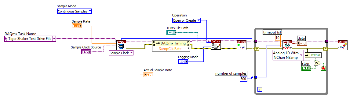
I'm trying to: record streaming channels (acceleration 21 and 1 tension) using a DAQmx task, then convert the data to a PDM file. The program files and output to the TDMS file very well. The issue I'm having is that I can't change the sampling frequency. I want to record 500samples/s and I can not get the "real sampling rate" of change of 1651.61samples / s. I am trying to use the clock to do this and I succumbed. I also tried to change the settings of "Timing" in the task without a bit of luck. Here is a screenshot of the .VI I created. I've also attached a copy of the file VI. Any help would be greatly appreciated!
Thank you
Tony
You will need to provide the model of your device. You can also look in the sheet/manual to see what the real supported sampling rates. Some devices have limited rates.
-
How to specify the sampling frequency? Must use "measurement & Automation Explorer '?
I use to measure the input current analog OR cDAQ-9171 (chassis only location USB) and NOR-9207. I have 2010 NOR-installed DAQmx and LabVIEW.
How can I specify the sampling frequency?
If I use M & A Explorer to create the task, I can specify the flow rate (Hz) on the Configuration tab-> sync settings.
For the acquisition of data NOR, it is mandatory to use M & A exploring?
If I don't want to use M & A Explorer, how can I specify the rate (Hz)?
Hello
You can specify the sampling frequency with "DAQmx Timing.vi" located in the function palette DAQmx (read context-sensitive help on how to use wisely).
You do not have to use M & A exploring (MAX) to create a task.
A simple and quick way is to use DAQ Assistant (same configuration as in MAX) to configure your measurement.
Another is to use blocks of DAQmx function to manually build your application code.
In my experience Assistant DAQ is ideal for simple tasks (one measure), with regard to the more complex measures (synchronized the analog and digital inputs).
I tend to use function blocks because they give you more freedom about code execution.
Note: You can also build DAQmx code from a wizard configured DAQ task.
Best regards
Matej
-
I have included my code as version 8.5 for those who have not yet upgraded to 8.6. I have also included some screenshots so that you can replicate the results I got. I hope that some signal processing guru can shed light on what I mention it further.
This VI convolves the signal of impulse response of a simulated servomotor which is essentially a damped sine the input pulse which is a step function. The signal resulting convolved should be IDENTICAL to that of the step response of the engine which is RED on the display 1. As you can see the convolution that results in table 2 shows the same structure of frequency, but its magnitude is INCORRECT. As you can see in the catches of 2 screen sizes differ by a factor of 2 & done the sampling frequency of the wave. Why the sampling frequency, impact on the scale is also very strange & disturbing.
Would appreciate any corrections & explanations so that I trust the convolution of the other wave forms of entry than just the step function.
OK, I think I have it working now. Your premise on the effect of sampling on the derivative is not the issue. Does it affect what the FREQ of levy is the basis of time of convolution. As the convolution product is not continuous but discrete the length of the array should be taken into account & the sampling frequency must be consistent with this length of array as well as 1 second corresponds to 1 second. If sampling freq is 2 kHz & the length of the array is 1000 then to get the correct time base by a factor of 2 must be taken into account. In addition, to take account of the DC, shift of the ZERO gain factor must be added to the convolved signal to get the correct size.
Thanks for making me think more deeply.
Maybe you are looking for
-
If the battery is fully charged charge can it continue to be plugged?
Maybe the battery can be damaged if she continue to be plugged to the charger unit once it has been fully charged?
-
LaserJet 4050: Problem install Laserjet 4050 in Windows 10 x 64
I installed upd pcl5 - x 64 - 5.9.0.18326.exe that has worked before on 7 & 10 64-bit Windows. Now, I get that the printer is in an error state or the printing error on HP LaserJet 4050 Series. I tried many drivers and no one works. The printer is co
-
Replication product Id after Sysprep cloning
Hello I have to configure 30 identical systems with Windows 7 Enterprise edition for my lab. I decided to install a machine, install all required software in windows and clone audit mode by using Sysprep with an answer file. For the activation part m
-
the sequence of workflow proxy settings
Sequence settings reflect the size of the original media or the size of the proxy? Can I use the 'drag and drop' again to create a sequence (with a clip that has a proxy in the project Panel)? Thank you.
-
I can't save a PDF with the same name
I can't save pdf files with the same name on the network drive in our society. I have full control over this network drive and can do anything create/read/write/change. Other programs work fine, but not Adobe Reader. I can save a pdf file with a diff