Alternating - Signal Express sampling frequency
Hi, Im trying to get data using Signal Express + NOR USB-6211, I put the sample rate to 44100 Hz. and everything seems to be ok, but when I checked the data I realized this time column does not increase in a period time constant (ie. sample FREQ not fixed).
For example:
1 / (Time (1) - Time (2)) = 43478,26 Hz.
1 / (Time (2) - Time (3)) = 45454,54 Hz.
and it constantly alternates between the two frequencies. I have to perform an FFT and Im not sure what is the actual frequency and which continues.
I appreciate any help on this issue.
Kind regards.
This seems to be a bug that NEITHER should be aware of if they are not already.
If you set the frequency of sampling to 44100, the actual sampling frequency will be (20 MHz / 453) or ~44.150 kHz. The USB-6211 case has a basis of TIME 20 MHz (±50 ppm) and this clock is divided by an integer to derive the sample clock. The sampling frequency is always be forced to match to the top if you choose a rate that can only be achieved with a wide divider. Regardless of what the file shows, map DAQ itself samples at a uniform rate (unless you use an external clock, or something like that...).
As for the behavior in the column duration... I know exactly how you look at it but I get the same behavior is written my data using 'absolute time' for the time column to an ASCII file (or by using a file LVM, which always uses the absolute time). With the help of 'on time' however gives me a correct result. I can't speculate on the cause... it seems likely to me that there is a comma floating rounding error (absolute time is in terms of seconds since 1904, so the software works with a large number at the same time requiring great precision).
Best regards
Tags: NI Hardware
Similar Questions
-
NI 6552 Signal Express sampling rate
I'm generating multiple signals for Signal Express. When I run them, some work well and others not, in other words, for some changes in sampling rate signals! Thera are two options in Signal Express: 1. read file waveform 2 sampling rate. to manually set the sampling frequency. In both cases, the rate is changed when I run the waveform of my 90 MHz to 100 MHz.
Any ideas?
Hello
The internal clock on the 6552 is generated from 200 MHz time base; Is that you can generate the frequency of 200 MHz/N where N is from 2 to a large number which takes up to 47 Hz. The driver for the Board of Directors will force the neerest value, so if you swipe from 90 Mhz to 100 MHz frequency, you will get 100 MHz in all cases. There is more information about the synchronization on the specs here:
http://digital.NI.com/manuals.nsf/WebSearch/E4C93B141B71ED93862573CC005E8EA1
Once, you run your project, Signal Express should show you the corced value, you can use this to read the actual frequency generated.
I hope this helps.
Juan Carlos
-
How to acquire the signal to very high sampling frequency
Hello world
My name is Luke Ho. I am trying to acquire the signal with Labview (Sthelescope). The signal comes from sensor acoustics, then filters and amplifiers to adapt to ADC rank (0 - 5V). Thus, the maximum frequency of the signal is 40 kHz.
According to the Nyquist theorem, I sampled at least 80 Khz signal.
Is there a sampling frequency devices like that? or y at - it another way of better? I used the Arduino before, but it was about 10 kHz.
I need your advice.
Thank you all and have a nice day.holucbme wrote:
Thanks for your recommendation
But is it possible without USB Data Acquisition, it is quite expensive for me.
This is the cheapest option to NEITHER. I tried to look for options to other companies, but more I found in the same price range, or not answering is not your condition of sample rate.
-
I have included my code as version 8.5 for those who have not yet upgraded to 8.6. I have also included some screenshots so that you can replicate the results I got. I hope that some signal processing guru can shed light on what I mention it further.
This VI convolves the signal of impulse response of a simulated servomotor which is essentially a damped sine the input pulse which is a step function. The signal resulting convolved should be IDENTICAL to that of the step response of the engine which is RED on the display 1. As you can see the convolution that results in table 2 shows the same structure of frequency, but its magnitude is INCORRECT. As you can see in the catches of 2 screen sizes differ by a factor of 2 & done the sampling frequency of the wave. Why the sampling frequency, impact on the scale is also very strange & disturbing.
Would appreciate any corrections & explanations so that I trust the convolution of the other wave forms of entry than just the step function.
OK, I think I have it working now. Your premise on the effect of sampling on the derivative is not the issue. Does it affect what the FREQ of levy is the basis of time of convolution. As the convolution product is not continuous but discrete the length of the array should be taken into account & the sampling frequency must be consistent with this length of array as well as 1 second corresponds to 1 second. If sampling freq is 2 kHz & the length of the array is 1000 then to get the correct time base by a factor of 2 must be taken into account. In addition, to take account of the DC, shift of the ZERO gain factor must be added to the convolved signal to get the correct size.
Thanks for making me think more deeply.
-
Analysis of frequency common time in Signal Express?
Is it possible to do joint analysis frequency time Signal express? I don't see in the section "analysis", so I guess that it is a separate tool that should be added, if possible still Signal Express. Help?
SignalExpress does not natively support joint time frequency analysis. However, check out the Sound and Vibration toolkit that expands the SignalExpress. It can do what you want.
-
Dear all!
I hope everyone is doing well!
Well! I am a student in first year of Labview and would like an expert on this VI opinion I did. I'm learning by doing! This VI is to see the effects of sampling at different frequency. I have a LABVIEW 8.5 and uses an express VI to simulate signal, two assistant screws DAQ etc. I also play a little with the number of samples and sampling frequency.
Come to the points that I did not understand!
1. the present VI crashes and I am not able to understand what is the reason?
2. the time scale itself changes as I raise the number of samples, even if I keep the same frequency sampling.
3. in addition, the peak frequency changes with the number of samples! Why?
I hope to have your kind response!
Thanks for your time!
Tajim
Hi Tajim,
Sorry for the late reply. I made a few changes to your VI and it works very well.
You can start with the choice of the same sample rate and the number of samples of the three waveforms. In this way, all will synchronize initially.
After that, you can try to change the sampling rate and the number of samples for the waveforms. However, you should becarefull when setting very large number of samples. If you have a low sampling rate, say 100 Hz and a high number of samples, say 1000 samples it will take 10 sec to acquire all the samples. If the second DAQ assistant is running at the highest sampling at the same time, you will have an overflow of buffer of data acquisition and it may hang. Of course it is a means to avoid this by implementing different structures in LV, but for the purposes of this test, you should be ok if you just keep this in mind.
Thank you!
-
How to find the sampling frequency to read the measurement file
Hello
I would like to find/extract the sampling frequency of a .lvm file.
Right now I am using the VI 'read file of measurement' and my data charge fine and all, but I need the frequency of sampling for certain calculations.
I know the header of the file .lvm that the sampling frequency is 1613Hz, but I want to get this automatic information from the open file .lvm.
Tried to find an express vi that could give me the answer, but I could not find a

I'm sorry if this question already answered, but I could not just to find the answer.
I hope you understand what I'm doing!
Thank you
Kind regards
Tommy
The timing is part of the production of signals information. Never use the functions of the Express, but you can use DDT to and convert to one of the data types of waveform. Waveform components then turns the dt.
-
How to acquire with NiScope at different sampling frequencies and lengths Records?
I need to acquire the data of 2 channels of the NI PXI-5114 map two different sampling frequencies high, at the same time. Also, I put 2 different record length. Is this possible?
I understand that 'Vertical' settings can be configured for individual chains because the function 'Vertical niScope Configure' has 'channels of entry with which we can assign the desired channel. But for horizontal settings such as "min sampling rate" and the record min length, I could not find such an option to specify the channel. Would it not common to both channels?
I hope that the device is capable of simultaneous sampling and therefore channels can be configured individually to different sampling rate.
Hi AJ_CS,
Why do you have to be distinct from sampling frequencies on channels separated from the digitizer even? What different sampling rate do you want?
But for horizontal settings such as "min sampling rate" and the record min length, I could not find such an option to specify the channel. Would it not common to both channels?
You do not have an option to configure the settings of hoirizontal on a channel by channel basis because this concept does not exist in the traditional sense of the use of a scope. Compatible with the concept of IVI, an oscilloscope traditional benchtop will have only a button or a set of buttons for setting the parameters of synchronization of the unit. There is therefore no horizontal configuration to separate channels on the scanners NOR.
I hope that the device is capable of simultaneous sampling and therefore channels can be configured individually to different sampling rate.
Similar to a traditional benchtop oscilloscpe, the device is capable of simultaneous sampling. But as mentioned above, the channels can not be configured for different sampling frequencies high.
However, you can ignore data that you think is not relevant. For example, if you assign 100MS/s CH0 and CH1 to 50 MS/s, then you throw all other samples.
Alternatively, you can use separate scanners (a channel on each digitizer) and configure them to taste at different rates. You can set frequencies of sampling on scanners NOR separated and even synchronize them with TClk.
-Andrew
-
Synchronization of the inputs and outputs with different sampling frequencies
I'm relatively new to LabView. I have a NOR-myDAQ, and I am trying to accomplish the following:
Square wave output 10 kHz, duty cycle 50%.
Input sampling frequency of 200 kHz, synchronized with the output that I get 20 analog input samples by square wave, and I know what samples align with the high and low output of my square wave.
So far, I used a counter to create the square wave of 10 kHz, display on a digital output line. I tried to pull the document according to (http://www.ni.com/white-paper/4322/en), but I'm not sure how sample at a different rate than my clock pulse. It seems that this example is intended rather to taste one entry by analog clock pulse. There may be a way to create a faster clock (200 kHz) in the software and use that to synchronize the analog input collection as well as a slower 10 kHz output generation square wave?
I eventually have to use the analog inputs to obtain data and an analog output to write the data channel, so I need the impetus of the square wave at the exit on a digital PIN.
How could anyone do this in LabView?
Hi Eric,.
All subsystems (, AO, CTR) derive from the STC3 clocks so they don't drift, but in order to align your sample clock HAVE with pulse train that you generate on the counter, you'll want to trigger a task out of the other. I would like to start by a few examples taken from the example Finder > Input and Output material > DAQmx. You can trigger GOT off the train of impulses, start by Gen digital Pulse Train-keep -you probably already use a VI like this to generate 10 k pulse train. AI, start with an example like Acq Cont & chart voltage-Ext Clk - Dig Start.vi-you'll want to use the internal clock so just remove the control of the "Source of the clock" and it uses the internal clock. From there, simply set the "Source of the command" either be the PFI line generates the meter, or ' /
/Ctr0InternalOutput '-assuming that you are using the counter 0. You'll want to make sure that the start of the task HAVE faced the task of counter I is ready to trigger off the first impulse. They should be aligned at this point. For debugging, you can use DAQmx export Signal to export the sample clock - you can then brought the train line and the PFI pulse to make sure that they are aligned.
Hope this helps,
Andrew S
-
High speed continuous measurement of encoder with sampling frequency of 1 kHz
I am able at all times the position of a linear encoder using a PCI-6602 counter card, and I need to know how to set up so that the counter rotating at high speed, but the data is inserted into the buffer at a frequency of 1 kHz. I am able suddenly to a hydraulic cylinder, and I am not concerned about the event recording to high frequency except to the extent where they throw off the number considerably if the equipment does not run fast enough to detect all the impulses of the encoder.
Now, I think is that the external sample clock signal control (routed internal pulse output counter) time rate whereby the equipment detects the impulses of the encoder and the rate at which it inserts data into the buffer. With a pulse 100 per inch encoder and a sampling frequency of 1 kHz, the extended final position of the cylinder is turned off by +/-0.15 inches, which is unacceptable.
I need calculate a speed of this information, so I prefer not to use software timed sampling to control this (it's more difficult programming for other reasons as well - several asynchronous measures). Any ideas on how to configure the hardware to count faster than the speed at which she inserts counties in the buffer?
OK, you're clearly on the right track here, so I will focus on some details.
1. How do you know that the +/-0.15 "differences are * measurement error rather than * error of movement? Why wouldn't be an accurate measure and a proposal which can vary slightly from the nominal value?
2. I wonder some all electric noise and defects that may produce false edges. The fact that the behavior was better by using a sampling rate limited (200 kHz) in the digital inputs may be that some of these flaws were so short that they were never captured.
I did a ton of work with the Commission to 6602 encoder and I can certainly confirm that count equipment is sensitive to the edges in a few tens of MHz. (I know its 80 MHz for edge counting, but I think I remember that it can be of the order of 20 to 40 MHz to accommodate the time of signal propagation extra of the quadrature decoding circuit).
A small point of clarification. You're talking about the speed at which the meter "works to. The value of count is a register whose value is changed completely by the circuit, * independent * of the sampling frequency. If you enjoy with material-clocked County in memory buffer or interrogation of software without buffer not a bit for circuits that increments / decrements the value of the counter register. (In other words, I am completely convinced that you would get commensurate with position end even if you took only 1 sample software-polled after the end of the move instead of sampling at 1 kHz all the way through.)
So, if the value of the counter is disabled, it is because the circuit detects producers of County of the edges that shouldn't be there. Something you can try is to set up digital debounce filter for input lines of the PFI corresponding to the encoder Source inputs and to the.
-Kevin P.
-
How to display the signal on a waveform graph in Labview Signal Express?
Hello
I want to display a signal in Signal Express 3.0 in a "waveform table", but don't know how to do it and I think that it may be impossible?
In Labview, there are two ways to view data, a 'waveform table' or a 'waveform graph. The great thing with 'picture of waveform' is that it allows you to set a length of history and you can see the data move to the left (option graphic strip) that samples are recovered. It works perfectly.
In Signal Express I can only select "Graph XY" or "Waveform curve" by doing a right-click of the mouse, but I can't select "table of waveform. Is it really true that it is not possible to view data in a graph of waveform "with Labview? (1 analog signal during streaming, 100 samples to read at the rate of 1 K)
Thank you in advance,
Enrique
Hi Enrique.
You are right that there is currently no graphic waveform in SignalExpress. The thing nearest you can join, is saved data under a log and then he looks one when recording (which I know this isn't quite the same interactive behavior).
For your last comment, you wrote 'waveform curve', but I guess you meant 'picture' here as well.
Sorry about that. We recently received this request, then perhaps in a future version.
Phil
-
Sampling frequency for two different routes for acquisition of data USB-6009
Hello
I use a box USB-6009 and incorporating the "daq assistant" to change the sampling frequency. I'm trying to find a way to set the sampling frequency to two unique values for the two separate channels. I tried implementing two assistants daq and different for each channel sampling frequency setting, although it does not work. Is it possible to set the sampling frequency for all channels, and then reduce the rate for another channel - or an alternative? I would be recognizing any input on this matter, thank you!
-Anthony
All tasks on a DAQ card using the sample clock should use the same clock. Therefore, you cannot have two tasks on the same sample of DAQ card at different rates.
Alternatives would be:
1. to combine all channels in a single task and to accept additional data
2 get an additional DAQ card to use at the same time
-
Sampling frequency and Nyquist theorem - data acquisition
Hi all
I have a rectangular steel beam that is affected with a weight of 100 kg and I would look for the modules able to sample the signal correctly.
The Nyquist theorem says that if half of the sampling frequency is higher than the input signal, it will be recorded correctly.
What I think about it before you buy a data acquisition module to find the signal of the rectangular steel beam? I will perform an analysis model by finite elements using the elastic properties or properties of plastic? Is the natural frequency of the associated structure of the input signal?
Thank you
Husband
Some technical assistance is appropriate, determine that the higher frequency component is interesting to your signal. Set your frequency of sampling to twice this value. In addition, to protect data, to build a filter of antisliasing of material it alleviates any energy above the highest frequency of interest.
Mike...
-
Any problem of loop sampling frequency
Hello
I am a student who did a thesis on the electric vehicle tracking system in labview. I collection of usb-6009 analog measurement data, transfer it in the daq assistant and state machine inside a while loop to do the follow-up process.
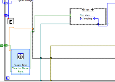
So, I have a State that determines the sampling frequency of the loop cycle, and I was able to modify this rate in the values of 0.1, 1 to 5 Hz, I realized that it with out of time VI Express, which is in a loop, but outside the case of structure for States. I'm going to rate last in time "Target Time" of entry and the Boolean output "Elapsed time" goes to the business structure, passing to the next state when the time runs out. In the next State, it resets the elapsed time and the cycle starts from the beginning.
Thus, everything works fine until I see in my log file (txt file where I save the measured values) it's only 3 or maximum 5 Hz frequency 4 samples per second.
I have a good enough computer with processor i7 and 8 GB of ram.
What could be the problem?
In the picture below it can be seen how I realized that with timer.
Thank you in advance.
Matej
As I mentioned in my previous note, your problem is that you start a new target for the time time vi ONCE your analog playback is completed. This ADDS essentially no matter what time is taken by Analog playback on top the time you ask vi of time spent waiting.
I modified your vi and I think that should take care of your problem of synchronization.
However, I suggest using "Wait until the next ms Multiple" because unlike the vi express you are using, one I mentioned allows other processes are doing their job in the meantime.
Hope that helps...
-DP
-
Application using Signal Express RTSI
Hello
I am interested in recording of analog signal synchronization (start time, acquisition of the sample, 3 cards PCI-6289 stop time) and possibly their synchronization with 3 to 5 more cards NI PXI-6221, that are connected to the same host PC via a PCIe-8361 interface PXI-8360. For now, I will focus on the 3 cards PCI-6289. I used a RTSI cable with VI recorder is no longer supported and guess that it works well with Signal Express. I've set up a device cable RTSI NOR able & Automation, which includes 3 PCI cards. 3 PCI cards are the only devices connected to the RTSI cable. When you check the properties of the RTSI cable device, I left all the boxes unchecked, that seems to be the right setting for my application. In Signal Express, when you add a device in the Panel on the left of data acquisition (analog voltage signals), I always see each individual card (Dev1, Dev2, Dev3, etc.), but there is no device RTSI. If I look into the advanced features of synchronization of each of the three panels DAQAcquire, I can apparently use a card as a master clock and the two other cards will have master card sync signals (is it automatically via the RTSI cable, or do I need to connect external clock out on the master card to the clock on the slave cards?) but once again There is no mention of the cable RTSI, or configuration of device RTSI in MAX. Using the clock of a card in a situation of master/slave help, but it starts and stops all three cards at the same time, or no apparent synchronization between maps will simply be a coincidence?
Any suggestions are appreciated.
Kind regards
Brian
You really need your question to the SignalExpress Commission. Few people here use it.
Maybe you are looking for
-
How to restore the old window download in firefox browser worm 26?
The old download window has helped me see my video through Downloader of video downloading side by side in the same time, thus allowing me to cancel it if found unfit after a few minutes. Even I could open the folder to view a few bites that have bee
-
Maximum number of e-mails that I can download in iOS9 is 150, how can I change this?
Maximum number of e-mails that I can download in iOS9 is 150, how can I change this?
-
Manipulation of Image data display
Hello So I'm a first time LabVIEW user and I am struggling with programming graphically the project I have to do... The type of data, I work with are bitmap images. Basically, a single image is there (along the y-axis) data and length of wave (along
-
HP G71-340US: network controller driver is missing
Hello. I need help. The wireless network in my G71 driver is missing and all while doing some research, I learned that to get what im after that you will need the follwing info to help me: Hardware ID PCI\VEN_8086 & DEV_0084 & SUBSYS_13158086 & REV_1
-
Ideas: Programs that you have problems with Windows XP Error messages Recent changes to your computer What you have already tried to solve the problem Remember - this is a public forum so never post private information such as numbers of mail or tele