NI 6552 Signal Express sampling rate
I'm generating multiple signals for Signal Express. When I run them, some work well and others not, in other words, for some changes in sampling rate signals! Thera are two options in Signal Express: 1. read file waveform 2 sampling rate. to manually set the sampling frequency. In both cases, the rate is changed when I run the waveform of my 90 MHz to 100 MHz.
Any ideas?
Hello
The internal clock on the 6552 is generated from 200 MHz time base; Is that you can generate the frequency of 200 MHz/N where N is from 2 to a large number which takes up to 47 Hz. The driver for the Board of Directors will force the neerest value, so if you swipe from 90 Mhz to 100 MHz frequency, you will get 100 MHz in all cases. There is more information about the synchronization on the specs here:
http://digital.NI.com/manuals.nsf/WebSearch/E4C93B141B71ED93862573CC005E8EA1
Once, you run your project, Signal Express should show you the corced value, you can use this to read the actual frequency generated.
I hope this helps.
Juan Carlos
Tags: NI Products
Similar Questions
-
Alternating - Signal Express sampling frequency
Hi, Im trying to get data using Signal Express + NOR USB-6211, I put the sample rate to 44100 Hz. and everything seems to be ok, but when I checked the data I realized this time column does not increase in a period time constant (ie. sample FREQ not fixed).
For example:
1 / (Time (1) - Time (2)) = 43478,26 Hz.
1 / (Time (2) - Time (3)) = 45454,54 Hz.
and it constantly alternates between the two frequencies. I have to perform an FFT and Im not sure what is the actual frequency and which continues.
I appreciate any help on this issue.
Kind regards.
This seems to be a bug that NEITHER should be aware of if they are not already.
If you set the frequency of sampling to 44100, the actual sampling frequency will be (20 MHz / 453) or ~44.150 kHz. The USB-6211 case has a basis of TIME 20 MHz (±50 ppm) and this clock is divided by an integer to derive the sample clock. The sampling frequency is always be forced to match to the top if you choose a rate that can only be achieved with a wide divider. Regardless of what the file shows, map DAQ itself samples at a uniform rate (unless you use an external clock, or something like that...).
As for the behavior in the column duration... I know exactly how you look at it but I get the same behavior is written my data using 'absolute time' for the time column to an ASCII file (or by using a file LVM, which always uses the absolute time). With the help of 'on time' however gives me a correct result. I can't speculate on the cause... it seems likely to me that there is a comma floating rounding error (absolute time is in terms of seconds since 1904, so the software works with a large number at the same time requiring great precision).
Best regards
-
Hello.
I have problem with maximum sampling on USB - 6259 of NOR. I measure the hearts of rabbits EKG and I need to know, what maximum frequency can I sample this signal. I use 10 channels and I don't know if the maximum sampling frequency is for each channel or one. I know, I use the sampling rate 1 MECH. / s, but I don't know if MECH. / s means MHz I do need knowledge rate (frequency) Hz sampling. I know that USB - 6259 OR maximum sampling rate 1 ms/s, and 16 bits of resolution. This means 2 MB/s, but it is for each channel, but only one? Can I sample my signal with sampling rate 1 MHz theorist?
Thak much for your answers.
Since you have only a clock unique convert and the channels are multiplexed, by channel sampling frequency is the rate divided by the number of channels max. In your case, you would be sampling each 100kS/dry.
-
Currently, I am trying to log readings of DC voltage with an AA battery in an ASCII using LabVIEW 2009 of SingalExpress file and the USB-4065 digital multimeter (DMM). I have two stages:
(1) acquisition of Signal > voltage DC using DMM
-resolution 4.5 with 3.333333E the value-5 sampling period
2) save in ASCII
-The value to add to the file, delete the file after each race
Faster reading, I can get is a data point written in the ASCII file every eighth of a second.
Furthermore, I am new and software OR LabVIEW, the LabVIEW SignalExpress software I have is only for evaluation as it was included in the CD of the driver for the USB 4065 DMM.
- Max (30 000 samples per second) sampling rate is only achievable by a LabVIEW VI?
- Don't I have the wrong settings for DMM step?
- Is it because I haven't activated SignalExpress and am only using the evaluation version?
Thanks in advance for any help!

Hello Lukos,
You are assuming that you need access to lower level functions in order to obtain the higher sampling rates. In order to get these speeds, we need to disable some settings that are not accessible via Signal Express. You can create a VI and then use a step VI call in Signal Express to stay in the same environment.
Kind regards
-Travis E
-
sample rate real vs min sampling rate
I'm sure it's an obvious answer, but here goes.
I have a USB-5132 ' scope and using niScope horizontal configuration Timing.vi I put, among other things, the minimum sampling rate. In my case, I chose 20 MHz, which of course gives a sampling of 50 ns period.
I use niScope reading (poly) .vi with the WDT variant to read waveform data. I noticed something very strange - waveform limit testing throw error 1802 "signals have a dt of different values '-if I put a waveform components unclusterizer Get on the wire of waveform and looked at the value of dt of the wave." He told me that my dt is 40 ns, which of course is of 25 MHz. I also plead for only 2000 samples.
So what causes this shift? Why the digitizer does not accept everything just my desired sampling frequency?
Austin Walton wrote:
Andy,
The setting of minimum sampling frequency is the frequency at which digitized
the samples are stored, expressed in samples per second. This setting is rounded
up to and including the next legal collection that supports your device. Ownership of the actual sampling rate calculates the actual sample used for the acquisition rate.Unless you specify another source of the clock, the digitizer uses an internal oscillator as clock source. For the 5132, this oscillator is clocked at 50 Mhz. When using the oscillator internal as the sample, the digitizer clock source can use versions split to the bottom of this clock, for certain sampling frequencies are not possible.
-
I am using a cDAQ 9172 with modules NI 9219, NI 9264 and three NI 9211. I'm looking to acquire signals out of the acquisition of data within a loop under continuous sampling. My program works fine if I set the number of samples to read 1-2 Hz, but I need to go faster than that. If I change the sampling rate, the loop is executed at this speed but sensors still read only in samples at 2 Hz and then duplicating over and over again. I was wondering if it was possible to read on 1 sample at the time of the acquisition of data at a faster rate. I know that the frequency of sampling on the sensors and data acquisition are much higher than that. 1 sample at the time of the Board of Directors has the limitatioins of being only able to run at 2 Hz? Please let me know
Thank you
Craig
Hi Craig,.
I don't know exactly what you describe. Are you feeding the DAQmx Read output in an express VI? Or are you using the express VI DAQ Assistant for the analog input task?
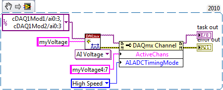
If you use the DAQ Assistant, you can set the ADC synchronization mode without changing your code:

If not, use the 'Active channels (if subset)' property to control the subset of channels on which your VI defines AI. ADCTimingMode.
For example, the following code snippet creates 8 virtual channels named myVoltage0 by myVoltage7 and sets HAVE them. ADCTimingMode on myVoltage4 of virtual channels through myVoltage7. These are in the cDAQ1Mod2/ai0 physical channels via cDAQ1Mod2/ai3:
If you leave off of the entry "name" on the string to create VI, then the virtual channel names are the same as the names of physical channel, so it's the equivalent:
And by the way, a right-click on the property and selecting "create > Constant ' context menu saves you from having to hardcode a number like 14712.
Brad
-
How to display the signal on a waveform graph in Labview Signal Express?
Hello
I want to display a signal in Signal Express 3.0 in a "waveform table", but don't know how to do it and I think that it may be impossible?
In Labview, there are two ways to view data, a 'waveform table' or a 'waveform graph. The great thing with 'picture of waveform' is that it allows you to set a length of history and you can see the data move to the left (option graphic strip) that samples are recovered. It works perfectly.
In Signal Express I can only select "Graph XY" or "Waveform curve" by doing a right-click of the mouse, but I can't select "table of waveform. Is it really true that it is not possible to view data in a graph of waveform "with Labview? (1 analog signal during streaming, 100 samples to read at the rate of 1 K)
Thank you in advance,
Enrique
Hi Enrique.
You are right that there is currently no graphic waveform in SignalExpress. The thing nearest you can join, is saved data under a log and then he looks one when recording (which I know this isn't quite the same interactive behavior).
For your last comment, you wrote 'waveform curve', but I guess you meant 'picture' here as well.
Sorry about that. We recently received this request, then perhaps in a future version.
Phil
-
Different sampling rate with the same connector AIO, Labview FPGA
Hello
I use LV 2009 with the new Toolbox FPGA and an NI PXI 7854R. I acquire an analog signal with a sampling frequency of 600kS / s. I need as the sampling rate for the processing of the data, but I also need the signal sampled with a much smaller, variable sampling frequency to a FFT.
I've attached a picture to clarify, in a simple example, I'm looking for.
I tried with the structure case only take each ' iht iteration, but did not get the expected results.
Does anyone have another idea how to solve my problem? Of the, "Resampling" express VI in the funtion FPGA palette does not help me.
Thanks in advance,
Concerning
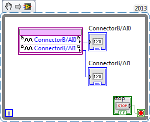
Hello
the connector for the analog input is a "shared resource", so you should he alone in your FPGA Code.
Find attached an example that shows how to perform this task of analysis.
Concerning
Ulrich
AE OR-CER
-
I'm new to myRIO and use it to measure sine wave (0V to 5V) of up to 10 Hz 20 KHz. I also quickly transformed of Fourier (FFT) of the signal measured in real time.
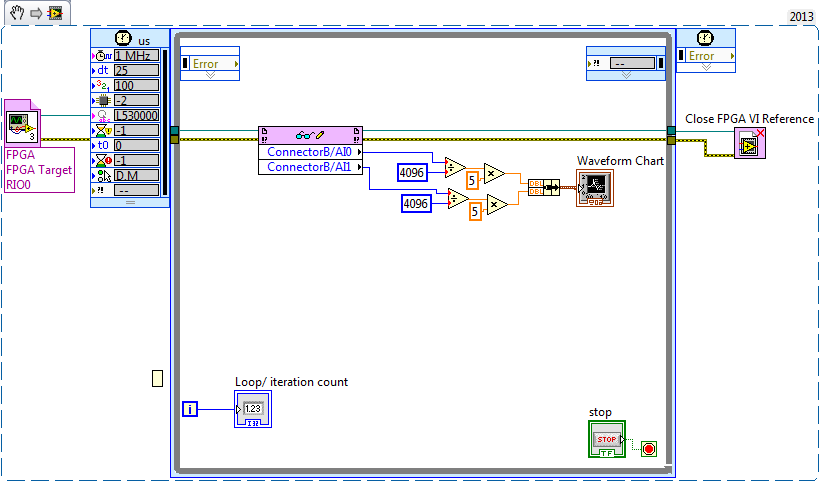
Sideways FPGA of things, I try to keep things pretty simple, just read 2 channels of AI (connector B: AI0 and AI1), therefore potentially able to read each HAVE 250 kech. / s (as the unit has a capacity of 500kS/s). Does that mean this program gets a two analog inputs data exactly every 4 microsecond? If this is not the case, how can I make sure that the data is acquired through a fixed sampling rate?
I realized that we can add to the FFT in FPGA function, but I wanted to manipulte the acquired data of analog inputs before it is sent to the FFT, which I don't know how to do now. Can someone explain me how do the arithmetic data (muliplication, division and so) on the acquired data and analog inputs to reducde the 12-bit resolution 10-bit to program FPGAS.
Later, I created a myRIO program to read analog data 2 FPGA program which continues to turn in timed loop. In the program myRIO, the timed loop is configured to 1 MHz clock source type by a delay of 25 microseconds.
This configuration means that the loop runs exactly every 25 microsecond?
When I set up the less than 10 micro second time, myRIO has stopped working. Why is it so?
Is it because myRIO cannot run as fast as FPGA?
It is advisable to make the FFT of myRIO side analog data or FPGA?
When I tried to do FFT using the power spectrum of myRIO side, he asked for waveform data. What I acquire is data analog. How can I convert in waveform data?
If I read in the forum for help, I couldn't have the full answer to my doubts
Discussions at the Forum I did reference:
A lot of good questions here, I will try to answer as much as I can so as to offer a bit of advice.
First of all, if you are looking to acquire data at a very specific rate on the FPGA, you'll want to use the Timer VI. You are also going to use a FIFO of DMA to transfer data of FPGA in real time. A node read-write using as you do now means you'll run out of samples, or read the sample even several times. The link below is a very good tutorial on how to do what I described above.
http://www.NI.com/Tutorial/4534/en/
Later, I created a myRIO program to read analog data 2 FPGA program which continues to turn in timed loop. In the program myRIO, the timed loop is configured to 1 MHz clock source type by a delay of 25 microseconds.
This configuration means that the loop runs exactly every 25 microsecond?
When I set up the less than 10 micro second time, myRIO has stopped working. Why is it so?
Is it because myRIO cannot run as fast as FPGA?
In general, you should not run a timed loop much faster than 1 kHz. Using timed inside loop knots, you can monitor the real rate of loop during execution to see if f you meet your needs of the moment.
The portion of your myRIO RT is slower than an FPGA in the sense where it cannot manage the rates of lines 40 MHz (he makes up for it by being able to work with much better pictures) and it is important to remember that it is just a computer. The advantage of a real-time operating system, is that you have more control on the Scheduler, not that he is faster (less jitter, not faster code). There is more good reading below.
http://www.NI.com/white-paper/3938/en/
It is advisable to make the FFT of myRIO side analog data or FPGA?
When I tried to do FFT using the power spectrum of myRIO side, he asked for waveform data. What I acquire is data analog. How can I convert in waveform data?
I would say that it is generally advisable to treat your FFT on the side FPGA as long as you have the resources available, but for many applications probably little matter ultimately.
-
6255 sampling rate causes the dc offset
I see a dc offset in the measures of analog input I select different sampling frequencies.
I have USB-6255 (mass termination) multifunction data acquisition and I use measurement and Automation Explorer to put in place my entries.
My raw analog input is-0, 6250 volts dc, I have set up a task that uses 4 differential channels with no custom scale.
I have defined the scope of the input signal to +/-0 .8v for you sure I get good resolution.
Acquisition mode is continuous, samples of read is 1 k and I play with the order of 10kS/s rates 50kS/s.
While this task runs in the MAX, I can put my cursor in the rate field and use the top and down arrow keys to change the sampling frequency. As I do, I can see the light changes reported as much as 150 MV rate from one to the other.
It is a significant change when the total time of entry is lower to +/-1v.
The direction of movement is independent of the increase or decrease of the sampling frequency.
For example,.
23kS/s, the declared value is - 0.540v,
24kS/s, she moves to-0.620v.
25kS/s, she moves to-0.690v.
26kS/s, she moves back to-0665v.
27kS/s, she moves back to-0.625v.
and 28kS/s, she moves to - 0.535v.
At first, I thought that the sampling change made a change of the input impedance and change the load on my source, however, all the time, my dc signal source remained at the - 0.625v (as measured with a multimeter fluke at the connection point to data acquisition).
Why this is happening and what can I do about it? I want to give my users the ability to choose their desired sampling frequency.
My guess is that I need to add an amplifier to fixed gain with a gain of 5 to 10 to make the input signal to use the maximum of the analog input level (+ / 10v).
I use MAX version 5.0.0f1
Thanks for any help,
Tobin
Hi Tobin,
What do you use to generate the signal-. 625 volt? If you are using a switching power supply, you can experience aliasing where the power supply is turned on and stop.
In addition, are see you the same tensions at the same sampling rate? See you always - .540v to 23kS/s or vary over time?
Finally, you have a second 6255 you can try to replicate this on? It could be that the unit is defective.
N
-
. VI filtering IIR and response: response of Butterworth filter size depends on sampling rate - why?
Hi people,
I'm not an expert in the design of the filter, only a person in applying them, so please can someone help me with an explanation?
I need to filter signals very infrequent using a buttherwoth filter 2. or 3. order of the bandpass 0.1 to 10 Hz.
Very relevant amplitudes are BELOW 1 Hz, often less than 0.5 Hz, but there is as well the amplitudes beyond 5 Hz to observe.
It's fixed and prescribed for the application.
However, the sampling rate of the measuring system is not prescribed. It may be between say between 30 and 2000 Hz. Depends on the question of whether the same set of data is used for analysis of the higher up to 1000 Hz frequencies on the same measure or this is not done by the user and he chooses a lower sampling rate to reduce the size of files, especially when measuring for longer periods of several weeks.
To compare the response amplitude of 2nd and 3rd order filter, I used the example of IIR filtering .vi and response:
I was very surprised when I found that the response of greatness is considerably influenced by the SAMPLING RATE I say the signal generator in this example vi.
Can you please tell me why - and especially why the filter of order 3 will be worse for the parts of low frequency below 1 Hz signal. Told me of people experienced with filters that the 3rd oder will less distort the amplitudes which does nothing for my the frequencies below 1 Hz.
In the attached png you see 4 screenshots for 2 or 3 command and sampling rate of 300 or 1000 Hz to show you the answers of variable magnitude without opening labview.
THANK YOU very much for your ANSWERS!
Chris
Hello Cameron and thanks for my lenses of compensation.
I can now proudly present the solution of my problem.
It seems to be purely a problem of the visualistion information filters through the cluster of the scale.
After looking in the front panel of the IIR, I suddenly noticed that the "df" of the pole size is changing with the Fs of the input signal.
For a Fs to 30 Hz, the "df" is 0.03 Hz so you see the curve of the filter with more points, see png.
For a Fs 300 Hz "df" is 0.3 Hz, so the curve is larger with only 3 points between 0 and 1 Hz.
For a 1 kHz Fs the df is 0,976 Hz, so there is no point in the graph between 0 and 1 Hz.
It's strange that for constant Fs, df of this cluster NOT reduced with the increase in the number of samples, as it does in an FFT.
However, I hope now the filter used now for the curves obtained with the proposed Lynn way and the response of greatness from the filter information fit together.
Thank you for your support.
Merry Christmas and a happy new year to all.
Chris
-
Analog LabVIEW myRIO data sampling rate
I have been using the myRIO to acquire the audio input from a microphone.
In LabView, I use the VI Express Analog Input to get the data.
I wanted to know if there was a way to increase the sampling rate of the data of this VI, or any what VI to whom?Hi ykhali,
Try to put the VI in a timed loop and set the loop to your sampling rate.
Kind regards
-
Hi talented engineers OR,.
I use PXI 5015, measurement studio and make acuqisition of data sampling rate 40 MHz. The command
niScope_ConfigureHorizontalTiming (vi0 40000000, 40, 50, 1, VI_TRUE)
is used to set the sampling frequency. However, when we check the signal of sampling, it is 60 MHz rather than 40 MHz. same thing happened when it is set at 50 Mhz. The actual sampling frequency is always 60 MHz. But when we created the frequency goes low to 20 MHz or 10 MHz, it works fine. We use an external 10 MHz reference clock, and I'm sure that the PLL is locked. We are a State control.
Everyone comes up with the same problem? Please let know me if you need more information about it. Thanks in advance.
Sincerely,
Bin
Hi Ben,
Unfortunately, the only way you can use a 40 MHz sampling frequency is if you import it into 1 PFI. The ditch down the method that we use with our advice on sample clock gives you only the integer values 1 and more. 60 MHz is your next best option.
Kind regards
-
than 25 ns sets sampling rate...
Hello
I'm trying to test the sampling rate of chassis cRIO 9103...
I created a simple FPGA project, for sampling sign this clock frequency of the FPGA equal to 40 Mhz (on by default). I applied 1 Mhz square wave to pin MISO DIO6/SPI, place one of the slots on the frame... I put a tick 'loop timer' in ' ' loop for every moment of picking (totally 32 sampling point).
input signals a cycle = 1000 ns (1 MHz) and I m planning see samples every 25 ns (40 MHz) on the graphical waveform. But the chart shows me only 10 points for 1 cycle like taking samples of every 100 ns instead of 25ns. (FrontSamplingRateObservation.png)
What is to be? If so, how can I get faster sampling rate...
I joined .vi photos of the project...
You can consider that the only timed cycle lines and the pipeline of the operation.
-
With the NI 9205 module Max sampling rate - problems
Dear friends,
I develop a project of lv, which makes and control system of engine dyno. The material is CRio-9022 with other cards and also 9205 for AI. There is an encoder for angle attached to the motor shaft with 3600 chatted by Tower as well as an index to indicate the end of a revolution. the output of the encoder is measured by card 9411. The speed of the motor is 1500 rpm. I measure pressure data and couple when I receive a 'tick' of the wheel. This means my sampling rate for pressure and torque each is 90KO/s.
but I was not successful to lead it. The program is great and I can show them, but I believe that there is a problem in the choice of material for the task. With the data of pressure and torque of the 9205, I also measure other channels for the controller output mass flow and temperatures. So in all I use 8 channels of the 32 available. But only the pressure and torque are acquired at the wheel-driven sampling rate. the rest are acquired about 5 times per second.
Since the 9025 is a multiplexing ADC, 250K sampling frequency is divided by the number of channels accessed = 250 K/8 = 31 K samples/channel. With this in mind, I decided to acquire data of pressure and torque with each beat 3rd rotary encoder, essentially on 30K samples/s sampling. However, I see a large amount of noise.
So I decide to average more than 1 second cycles (so the engine runs at about 25 cycles/sec, I averaged over this issue). The resulting pressure and torque graphics do not match with those measured by an oscilloscope in terms of amplitude but the frequency and shape is correct.
I noticed an interesting feature in the charts. When I pass interpolation between the points, I see several curves made by points instead of a continuous locus of points. Accordingly, I find that the acquisition is slower than necessary, and so there are less number of points sampled as required. These points are not synchronized 25 cycles I have on average and therefore the separate "curves". It is because of the possibility that some points receive a higher number of 'contributions' several times (when you add), the neighbouring points.
so I conculde that the 9205 is not fast enough to do the job. also noise, perhaps due to crosstalk or gosting when the mux changes channels. the impdences output pressure and the couple are of the order of 10 K ohms.
the Labview code outline: well, there is a vi FPGA, which takes the rotary encoder ticks and sends a signal to the case of each 3rd tick. The signal contains a 16-bit integer, indicating the number of ticks. This signal is sent to a 1 element FIFO. This fifo is read in a parallel while loop, where it remains awaiting a new element. The while loop bed fifo, where data are available, takes a measure of pressure channel. A node memory of the method is called to provide data according to contained in the index number equal to the number of ticks to signal fifo. Then he adds the current pressure reading to the reading of the memory and stores the sum in the same memory location. Thus, an array of elements of 1200 is formed, where each elemnt is a sum of the values taken of more than 25 cycles. This memory is transferd to a dma fifo and reading side host. is done similarly to involved couple. host-side the fifo is read and divided by 25 to get the average. This average is displayed on a waveform graph.
Please check the attached file to get an idea of the problem. Sorry for the long post.
Please suggest if you understand the problem and suggesstions or solutions.


Maybe you are looking for
-
Share the iMac screen and keyboard with Mini?
If I have a Mac Mini, can he share the screen and the keyboard of my iMac (27-inch, 3.4 GHz with OS X 10.11.6 end 2012)? Or I need additional hardware on my desk?
-
I can't load Firefox. I get the message unable to load XPCOM. How can I get Firefox to load?
-
I use Outlook but now unless I open the file I can't print emails that I was doing. Also when I do he prints all of my boxes on the left side and print then only part of the email. It seems more to be like before printing option
-
just downloaded firefox 8 and disabled mcafee site Advisor how to get back to version 7
just downloaded firefox 8 and it disabled the Advisor site on my mcafee security suite. How to get back to version 7 until the site Advisor is compatible with version 8?
-
Windows activation - new hard drive and reinstalled Windows, but will not work with the product key
Hi all My hard drive died so I put a new in and installed Windows on a drive, but when I have just activated and put my product key does not work. In fact, I get this day by putting in and then it says character not aloud. Please can someone help? Al