RS422 PPS signal generation
I am trying to generate a RS-422 PPS signal using the PXI OR PXI-8431/8, LabWindows/CVI and CVI standard library functions, but I can't find a way to produce a signal that remains HI with persistence for X number of ms. I realize that use the PXI-6602 would be an ideal solution, but in my case, I am relying on the RT OS to maintain determinism. Do you know a white paper or a thread that could describe a reliable way to do this with the functions of the ICB boards of series I have?
This message has been copied since the LabView discussion Forum. Sorry for the inconvenience.
Sean,
I've updated the functions of generation of pulse with those of the DAQmx library and am now running.
Thank you a lot for the input.
J
Tags: NI Software
Similar Questions
-
USB-6501 open collector signal generation
Hi all
I have carefully read the manual for this product, and I think that's what I'm looking for, but I was hoping just to get confirmation from someone who knows a bit more about it as I do. I have a stepper motor command that accepts control impulses. The differential voltage between the 2 input pins must be between 2.5 and 5 V DC. The control pulses can be RS422 or open collector type signals. The maximum heart rate is 250 kHz, pulse length must be greater than or equal to 2 microseconds and the time between two pulses must not be greater than 40 milliseconds. The engine must operate continuously for an extended period of time. Yet once, seeking confirmation that DIO can produce the signal I need. Thanks for any help.
It seems to me that this module can be adapted to be connected to your driver module. Output configuration you need is called "open-drain output" in the data sheet.
It is possible to drive a stepper motor driver with a generalist module e/s. But (in most cases), it is NOT possible to drive of a driver of motor Stepper with a constant pulse. You will need a rate of acceleration, i.e. it must increase the frequency of the pulses of zero to the desired speed of the engine.
-
Timed signal generation TTL with the NI USB-6501 to be read by Arduino Uno
First of all, I want to apologize - I am very, very new to LabVIEW and brand new to the development of the software of control equipment in general. I tried to find an answer to this question already, but I'm not entirely sure what I'm looking for.
I have currently a work program LabVIEW which operates a gun card NI USB-6501. Due to the nature of having a machine that springs from a powerful beam of electrons, we want to assure you that if the computer controlling stalls or fails for any reason, we have built-in security that can stop the gun. Our current idea is to connect an Arduino Uno on a PIN on the USB-6501 and LabVIEW to generate a timed signal, which may read the Arduino. If the signal fails (indicating that the control computer has queued or off), the Arduino triggers a power relay that is independent of the control computer and turns off the gun.
I understand that the USB-6501 operates on TTL signals, so the signal that I should be something in the sense of "output TTL high, wait 1 second, output low expectations, a second, repeat TTL ', but I have no idea how to go about programming in LabVIEW. My first thought was that it is a square wave by using the function "simulate the signal" output, or to have trigger an iterative Boolean signal, by using the function 'DAQmx write', but I don't really understand how do to implement or another idea, or if an idea would even work.
Any advice would be greatly appreciated.
Hi Elizabeth,.
THINK THE STREAM!
When do you DATAFLOW think everything falls in places!

Several problems:
-You have to put that MAKE impulse VI in his own loop parallel to your main VI!
-When you place this generation of impulses in the effects loop ("TTL arduino low-high") you should put the CreateTask and StopTask outside the loop: no need to create/stop the task in each iteration.
-Why are there points of constraint to waiting functions?
-Why is there bent wires? You know Ctrl-U?
-LabVIEW comes with an extensive library of example screws: you looked at all these examples DAQmx?
-Suggestion: Learn more about the "structures of producer-consumer"!
-
Hi guys,.
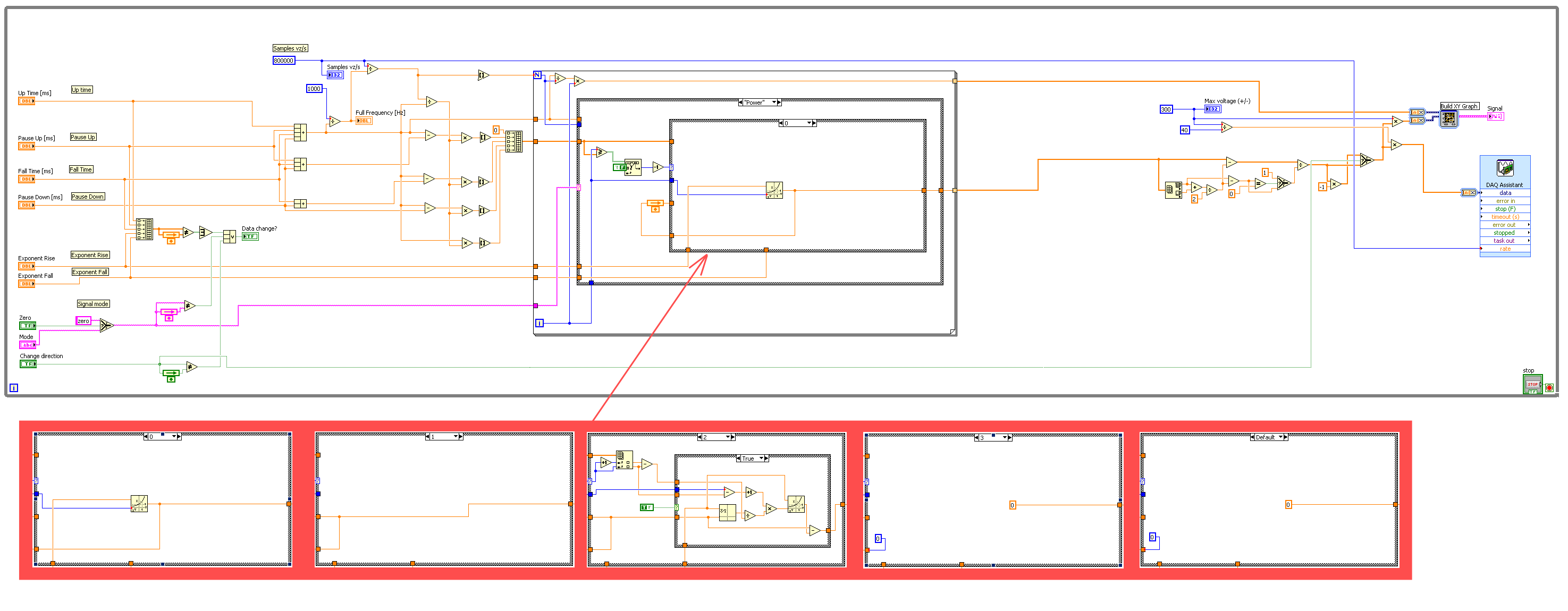
I have big problem with my signal generator and have no idea where can be a problem. I did a LabView program to make the signal that I am the phone my NI PCI-6221 card thanks to the DAQ Assistant. My program is:
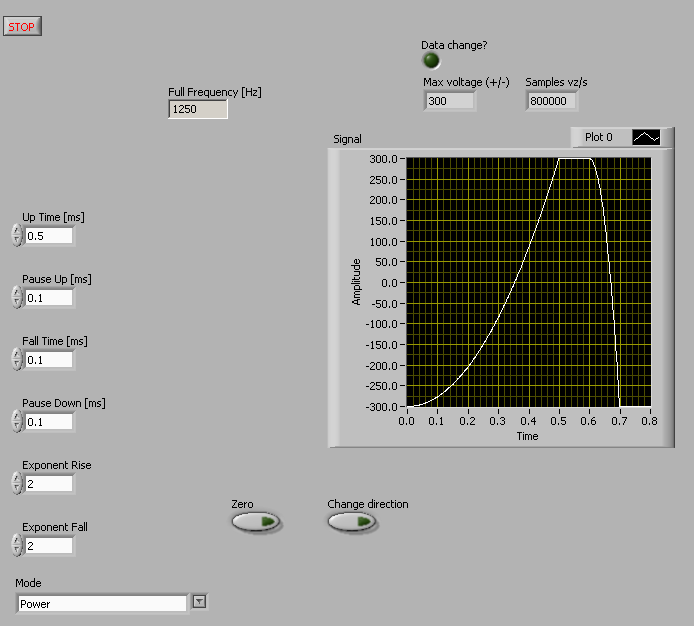
The Panel fromt with indicated generated signal is:
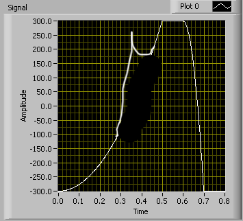
But my problem is with the evolution of my signal parameters in the build process. For example when I change the weather, so the square exhibitor will take more time, I see on my osciloscope some rest of the previous signal. So the final singal (osciloscope) looks like this:
(Sorry for the hand-painted painting)
If I stop the program and start it again the new signal with new parametrs is built perfectly. So I think that the PCI 6221 once I have changed some settings is not throw all the data in the buffer (at least I think). For the DAQ Assistant, I use continuous sample with 800 k samples per second. With this mode (continuous sample) I get this remain on new signal signal. When I tried to use N samples mode, it seems to work fine, but generation time is really slow, medium, once per second and I need to use my card for data rading too so it's out of the question. I tried to program this PCI card manually write function (instad of DAQ Assistant) too, but then I ger hard signal which is really not so smooth from DAQ Assistant. I evn tried to change the number of samples each time when I change some parameters, but it did not work. I'm sure I'm doing something wrong, but after two days of looking for a solution, I'm out of ideas. So question is where can be the problem and how to change signal parametrs without obtaining this rest of signals, means how to clear buffer completely when I changed the signal. I use LabViw 8.5 but it is possible to use any newer version too, if you think that old version of labview can be the problem.
OK I found the solution, it was impossible to use the normal function of Express DAQmx. After that I changed slightly this explicit function block, everything was fine. It was necessary to recalibrate the output of my card every time when I changed one of my settings. So whenever I changed something, I stopped my bit of any communication outupts and reinicializate of my PCI card.
-
Good evening
I am trying to generate an output voltage and I am facing some problems. I am using an analog input voltage NI 9263 module, I have two sons (AO0 and COM) connected to the terminals positive and negative a BNC connector; I want to generate an alternating voltage, 60 Hz and amplitude of 1 to 5 V. Unfortunately what I measured with a multimeter is something always scaling, for example: if I generate a signal of amplitude 1 I measure 0.7 volt, if the signal is amplitude 2 to I measure 1.4 and so on. I would like to know if some of calibration is required or there are potential errors in what I do.
Thank you.
Sorry, but am not at all in agreement with this response.
A BNC connector has no impedance any of its own. The output impedance of a signal generator is determined by the circuit, not by the type of connector.
Anyway, even if the output of the circuit impedance is 50 ohms, it is not the reason for your reading. The mulitmeters input impedance is high enough does not create a voltage with an output drop rather low impedance. The reason is probably the difference between a peak to peak of current voltage alternating (AC) and the RMS value. In your case, probably the software defines a range of crete and an RMS value is measured by the meter. The effective value is always the peak divided by (root of 2) value.
See also
http://86.43.94.97/moodlecp9a/mod/glossary/showentry.php?CourseID=1&concept=RMS+voltage
-
Hello
I would create a program that simulates the signal given by the contraction of a heart Chamber. It should be periodic with an adjustable frequency and amplitude. I use a structure of the event with a time-out interval equal to the time interval of the signal and a block "simulate arbitrary signals." The problem arises when the signal trace because the graph shows all forms of wave side by side instead of not not been zero only after than all of the time interval. You will find attached an example of signal I would get and that I receive and the labview VI.
I hope my question is clear, thank you in advance for the help.
Federico
So, you want something like that?

-
Analog output of signal generation custom
Hello
I have a VI that generates a signal from the values in an excel worksheet. I'm trying this waveform through an acquisition of output data. I use a box NI USB-6211.
I copied the exit code for the acquisition of data from other VI that generates a sinusoidal signal coming from an excel worksheet. This program works very well. (attached for reference - Analog Output VI + sinusoidal waveform)
I have two problems at the moment. First of all, I get error-200560 about waiting until the function, attached.
Second output amounts only to about 5.5 v instead of 9V specified in the data.
My VI generate several types of waveform according to selected tests, but I'm trying to get an output DAQ working with the first test, named "disconnection of the battery" work first before implementing it in the other tests so please ignore others for now. To run this battery select VI disconnect under tests select then direct to the attached excel (BD values under 10V) file.
I hope that I myself have pretty much explained, otherwise please ask for more! I'm new to LabVIEW so your help would be very appreciated.
Thank you very much
Parker
aeParker wrote:
I've made a few improvements to the VI but I always feel the DAQ 5 Cap output, 5V.
Dear Parker,
I guess that this statement is based on the values in the chart show, AO 0. However, this is not (necessarily) the voltage produced by AO 0, but rather the tension being sampled by AI0. If you look at the DAQmx create channel for the AI voltage channel, you will see that you have left entries Maximum and Minimum Value unwired, which means that they take their values default to + 5v and - 5v. This may explain the behavior of cutting that you observe. Try the + 10 and -10 wiring and see if that solves this problem.
Bob Schor
-
Cannot find examples of generation signal
Hello
Here is the page with information about the signal generation modules
http://zone.NI.com/reference/en-XX/help/371361H-01/lvanls/signal_generation_vis/
At the bottom of the page, there is information that these examples can be found at the following location:
labview\examples\analysis
But in my version, there is no file examples\analysis.
Where can I find these examples?
Thank you
This link is LabVIEW 2011. One of the best features of 2013 was a complete redesign of all the examples! Look here
\examples\Signal Processing\Signal generation directory -
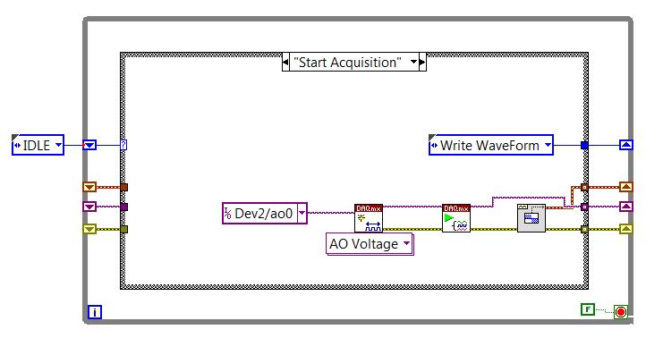
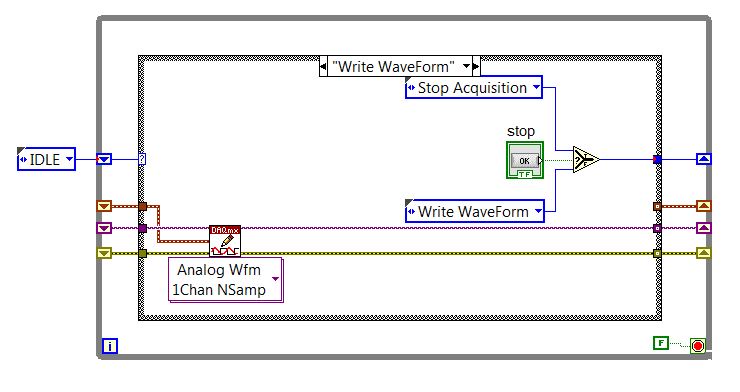
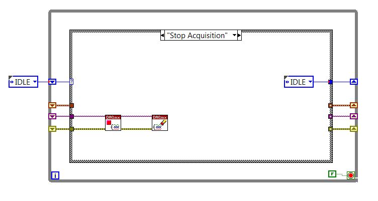
Order of generation of the signal with the command START/STOP (State Machine approach)
Hello
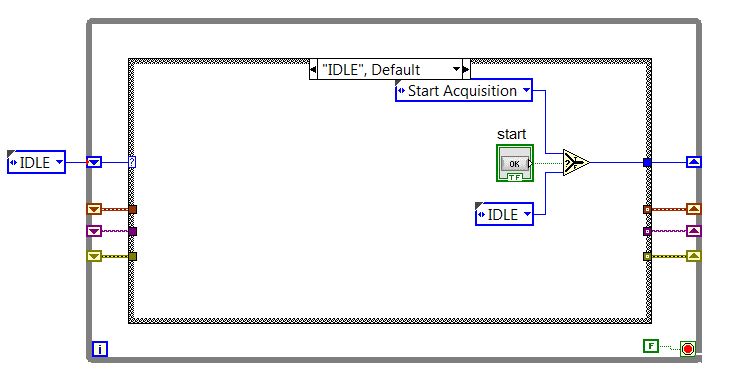
I met the problem with the realization of control (START/STOP) signal generation using state machine.
There are 4 States in the computer status (see 4 screenshots below).
The problem is when I click the button START, only a short series of generated pulses.
What is the staff of task_in/task_out issue, which is not properly managed?
Thanks in advance
Pavel.
Oh... you have defined with the mechanical switch action up to published... Right click and go to mechanical Action > latch when released. Do the same for your Start button.
You took a second to read down hold value, because your writing acquisition takes on this subject for a long time, apparently.
The stop button the Application, I did switch when set to released. It is set to the switch so that it can be used as a local variable in the Acquisition State stop as Idle.
-
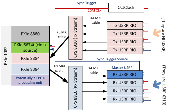
Problem of generation of Sync trigger in several synchronization USRP RIO 2943R problem
Generation problem shutter Sync in several synchronization USRP RIO 2943R problem.
Previous SR you may already know I'm stacked in USRP RIO multiple synchronization problem, especially in the mode based on the signal. Now I can cut down, the problem is mainly due to the outbreak of sync signals generation.
First of all, I read the article and the discussion in the following two links:
http://forums.NI.com/T5/USRP-software-radio/how-to-synchronize-multiple-USRP-Rio-294x-devices/TD-p/3...
http://zone.NI.com/reference/en-XX/help/373380D-01/usrphelp/synchronization/and I did my connection of the material according to the suggestions in the second link. My system schematic is shown in the following image:
I checked OctColck and SMU 6674 T connections. They are all connected correctly and the cable are fine. I use the niUsrpRio200_XcvrSyncPps.lvbitx.
According to the description of documents and discussion forum, the USRP RIO 1st in the list of devices are considered to be the USRP Master. Then, the FPGA to master USRP RIO released "trigger of sync" signal through the 'PPS Trigger Out' SMA port in RIO USRP box.
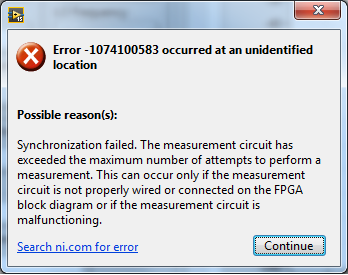
Based on the my analysis of the system, the first impression I have is the USRP Master does not export the 'sync trigger' correctly. The host VI reports the error like this:I was trying to measure the "synchronization trigger" using oscilloscope, but I found that it is impossible, because the host VI can not yet run, so there is that no signal can be seen from port 'PPS Trigger OUT.
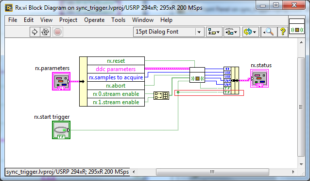
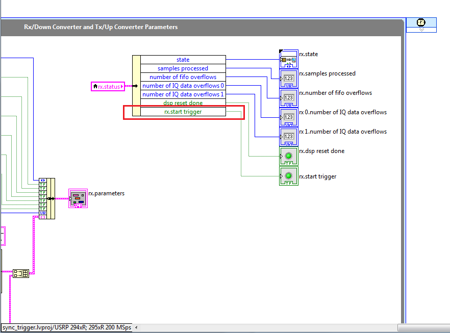
So I think that if I can watch this signal "sync trigger" in home VI by importing this signal from FPGA to host VI. I did some changes on the FPGA VI as shown in the following image to watch this signal of façade of the host VI. but not so successful. the rx.start tragger relaxation and tx.start do not appear on the host vi read/write control function.
-
Hello
I'm trying to simulate sinusoidal signals like speed signals. With amplitudes of Min and Max 5 and 12 V. The beach is 10 Hz to 800 Hz. The output impedance should be 100 ohms and should be rising 800 Hz soft switchable scan @ 7% per second.
I configured the sliders for the amplitudes of the 5 - 12V, as well as for the frequency range. The wave freezes when the frequency is close to 800 Hz. I configured the sample to 8000Hz rate that is 10 times of 800 Hz still no appropriate waveform.
I also hurt in soft switchable scanning configuration and the impedance.
Help, please.
Thank you.
Thank you very much Dan_K.
I love your sinusoidal signal generation method. I would watch the impedance and frequency again sweep. You have been very helpful and informative.
-
niHSDIO dynamic generation and Acquisition using LV configure Trigger VI
Hello!
My experience is limited within the environment of digital programming; Nevertheless, I have worked on this problem for a few days and would appreciate some comments if possible.
I am trying simply to generate and acquire a duty cycle of 50% of 8 MHz TTL pulse train on a PIN DIO of the PCI-6541 and acquire back from the signal on another axis of DIO. I have a connector corresponding to the embedded 6541 VHDCI connector which of course the generation and acquisition DIO welded pins to provide a loopback effect.
In short, I use the niHSDIO configure Trigger VI (instance--> start Trig: SW), niHSDIO send software Edge Trigger VI and write Named Waveform VI (instance--> data: 1 D U32) in the generation section. For the section of the acquisition, in short, I use the VI of waveform Fetch niHSDIO (instance--> single record: WDT).
I see results in the waveform acquired showing the generated and acquired digital TTL pulse on the respective DIO pins train, but I can't seem to get my 8 MHz frequency requirement. In addition, the lower part of the assignment of pin DIO, more frequency. Unfortunately, due to the configuration system required, I have confined myself to pin 12 DIO for the generation of digital pulses. Even with a 50 MHz clock frequency, I'm ~ 6 kHz of frequency acquired max. I looked at changing the parameters of the wave form VI named write, but it is not possible because the VI call a library function node. I also tried to generate a waveform of 8 MHz through a VI of generator of digital model, but I do not believe, you can trigger on generated waveforms? It seems that you must generate data using a simple loop to as a counter and sending the result to the waveform VI named write. Are there other ways I can simply generate and acquire a digital signal of TTL of 8 MHz (no external connection)?
In any case, any kind of feedback would be greatly appreciated.
Thanks in advance for your time.
Dan
Dan,
Sorry about the nomenclature. I usually use 0 x or 0 b for indication of radix, it is not necessarily a kind of standard, just what I used in my old days of the Assembly.
Looks like you have a knowledge about the data. Basically the material is just save in DRAM an array of words of 32 bits, with each bit corresponds to a data channel and each element being generated to the sampling clock rate you enter to your vi. Everything else is just easy data manipulation or usage. The interleaving method is just as I like to create a toggle model. You can easily do a loop with an inverter and feedback node or use on the construction in screws to signal generation. In addition, you can use the software digital waveform editor or control panel test to generate the county or toggle modes.
Give us an update when you enter the laboratory and let us know if you encounter any other disorder.
-
frequency of measurement of digital random signal
Hi all.
I want to measure the frequency of the signal. This value will be sent to any other device to vibrate the vibrator according to the value.
For example, I want to measure this signal:
I try to use your vi and extract single signal measure vi, but the result is not fair, for example, if I have no pulse on the graph the result is 11, 5 Hz (it should be 0 Hz)
I use assistant NI USB-6210 and acquisition of data to get the data from the sensor
Laughing out loud! All that motivates you... I don't see attachment. I commented on the block diagram on the vi attached which may help. What you can do in your data acquisition program, use is get the queue with the name of data. Then take the waveform of the DAQ assistant and use waveform components get to retrieve the values of the real signal (-1 to 1). Now use a loop with automatic indexing on table of signal and inside use enqueue to place each value of the signal on the data queue. In the joint programme filter, you can either copy the lower node in your program for the acquisition of data, or remove the loop of high signal generation and run them in parallel. The nice thing about the queues is that they can transport data between different vi on the same computer that the name is the same. If you want to do something with the frequency measures, while you can use a different queue for buffering of the data out of the loop of measure.
Good luck!
-
Independent of the 40 MHz clock Onboard FPGA PPS GPS meter
Could you give me some advice or point me in the right direction?
I need to time counter accurate/tick synchronized by GPS PPS synchronization signal.
I got cRIO S.E.A. GPS Module that trigger PPS signal at the bottom of basket FPGA. PPS rising edge signal precisely mark the beginning of the second.
When I measure the number of ticks of 40 MHz clock FPGA embedded in a (PPS) second number of ticks is not 40.000.000 ticks but something like 39,999,800 ticks.
I want to measure with precision time between edges up/down digital signals. Because the clock of 40 MHz FPGA are drifting I can't use it.
How could set up my own witch counter ticks will be put away with signal GPS PPS?
I don't expect that I could provide 40 MHz FPGA on board the oscillator.
Should I create my own counter which will increase the opposite by the value 1.000,005 (40 000 000 / 39,999,800) each tick and this counter will be running timed loop (chronometric 40 MHz FPGA embedded base). Increment the value (1,000...) will be updated every seconds dependent PPS vs FPGA clock drift.
My configuration: cRIO-9025, cRIO-9116, S.E.A. GPS + cRIO module, high-speed DIs NI 9402, RT/FPGA LabVIEW 2011
Looking forward to your hearing you.
PeterHi all
This could help you.
Timekeeper FPGA
- http://digital.NI.com/public.nsf/allkb/EFDC35727D4F2CC086257A0700693003
- https://decibel.NI.com/content/projects/NI-TimeSync-FPGA-timekeeper
(I do not understand how this could be released on 23/05/2012)
-
Create signals that are customized by using the spreadsheet of settings.
Hello
I'm quite new to LabVIEW but I have a complicated program to create. This framework requires a waveform from a spreadsheet of settings, attached.
I have attached a chart of the appearance of the waveform. As you can see the different parameters related to durations and amplitudes of the wave as well as the frequency and the amplitude of the sine wave in the middle.
In addition to this the program must travel creating each waveform in succession that the values in the change of worksheet for each different test.
I managed to read the file in spreadsheet, make a chart from this and then I tried index table online to send to a loop for which would go through each test, but I don't know how to create the waveform of these values. I have tried to use the labView signal generators to create individual sections of the wave but struggled.
Thanks for any help.
Combine the GERD and my suggestions. I had not used the Signal generation pallet front screw, but they manage most of the "math" for you. The key step, you have to decide is what interval to use for "dt", "quantum" time, usually the same as the sampling interval. Looking at your picture of waveform, you have a pulse, a ramp, a series of sinusoids, another ramp and a final push. When you look at an individual Palette, it has parameters "dimensionless" you need to adjust to your particular situation.
Consider the ramp time T3, starting at V1 and ends at V3. Assume that your sampling interval is "dt". You samples, end, thread and start entries in the ramp model based on the samples as follows:
- samples = T3 / dt
- end = V3
- Start = V1
Since you continue where you left it, I think that you do not want to "exclude the end?" thread true (to avoid double points), but I could be wrong on this matter.
To the sinusoid, you have need samples, amplitude, phase and cycles. Samples is again the total length of the sinusoid divided by dt. The amplitude is one, phase is 180 (notice that your sinusoid starts negative), and cycles is however several cycles you want during the period of the sinusoid. This sine wave, however, will be about 0, so you will need to add the offset constant V3 on the table.
After having assembled all the pieces of this wave form complex and are concatenated berries resulting from it, have to turn them into a proper waveform. Drop a wave function of building on the block diagram, drag to the top of its upper part a 'click' to expose dt and wire in dt and your table (Y). You now have a good waveform.
Bob Schor
Maybe you are looking for
-
Impossible to upgrade the driver Nvidia of Satellite P200-144
I downloaded the latest driver from the download from toshiba site as the Nvidia site does not support my card - Go 7600. When I run it it fails right at the beginning saying that the OS is not Vista x 32 - which it is! I updated the BIOS to v1.70. D
-
Hello! I write a labview program with the method of OOP (object oriented programming), and the program is very well. But when I build to exe, the manufacturer of labview display warning message: "LabVIEW has prevented a file name collision during the
-
Windows updates fail. Get the error 80070005. have the sony vaio. Windows Vista. component services freezes when trying to extend your computer
-
Hi I need to register ole32.dll but it fails. I get the following message: The module "ole32.dll" was loaded but the call to DLLRegisterServer failed with error code 0 x 8007005. I made in the framework of trying to solve a problem I have with MSOff
-
HP Pavilion dv6837el monitor problem
Hi all... I have a HP Pavilion dv6837el with nvidia geforce m8400gs, and since yesterday, I have some problems of monitor. When I start the laptop I see not the views of the bios loading, the monitor starts to run when windows is in place, too, the r