Generation of waveforms digital series E to 1 Mhz
I want to now that how we generate digital waveform series E through sampling over or contineous. I tested DAQ assistant produced error on the sampling options mentioned above and only worked with sampling of request?
As we already mentioned, your device does not output digital material support timed. Exactly what means the error message. At the request of the software means timed i/o software. means of nothing greater than about 1 kHz timer and which would have significant jitter.
Tags: NI Software
Similar Questions
-
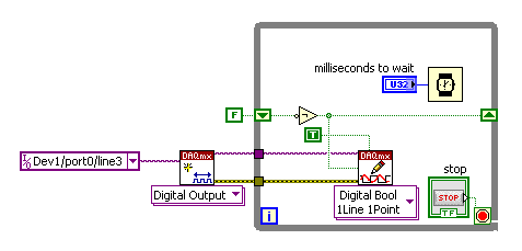
MyDAQ - generation of a digital signal and display on an analog waveform graph
Hello
I use the MyDAQ OR generate a digital waveform with a Frequency adjustable. This is implemented in a program, I already wrote it, which generates a TTL 'like' impulse out of the sound card. I display the result on a graph of analog wave form, and I would like to be able to display the digital signals generated by the myDAQ on the same graph. (Not in the same time, one or the other, activated by a button). I've been messing around with tables and conversions, but I can't really do with all this.
It's the vi, I did to generate the digital signal of frequency with MyDAQ. Any suggestions on how to do this if the following is false, would be great too, as I just got the MyDAQ a few days ago. I think there must be a better way, but it's the best I could come up with so far.
Hi Jonny,
The General logic, that you use to create a digital pulse train is very good. This VI you wrote should work and create the pulse train based on timing of software (which is fine because you have not DIO clocked by the material on the myDAQ anyway). However, it is generally advised to start the DAQmx task just before your time loop and then disable the task after the while loop when you press stop.
For reference, there are a few examples of good enough LV that I recommend you watch too much for this application. If you try just to create a digital pulse train, the example Gen dig Pulse Train - Continuous.vi is a good example that uses a counter to create a digital pulse of your desired frequency train. It is generally the preferred method to create a pulse train, if you have equipment available to do (the myDAQ there a meter). Otherwise, there are a few examples DIO who write continuously in a digital line / port.
If you are unfamiliar, you can find the examples by clicking Help > examples find... into LV then navigate to hardware input and output > DAQmx > generating digital impulses or the digital generation.
Also, here is some additional information on the myDAQ and its counters:
Hope this helps.
Chris G
-
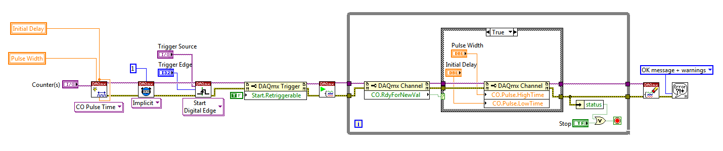
Hello
I use a mx-acquisition of data (NI USB-6211) and I would like to use it to generate a pulse of digital modulation
that is triggered by an analog input signal. The input signal is a pulse of squares analog modulated
What is almost periodic. It's because of my set up, and I can't do anything with it. I would use the
before the edge of this signal to trigger the production of a digital pulse signal modulated (0-5 V). My
problem is summarized in the figure given in the annex. I would also like to have the possibility of
Configure the 'backwardness' and the term of "TAU_LED", while the VI works.
I have looked at several examples of instrument OR meter generation, generation of PCI I / AO, but doesn't
not managed to solve my problem. Does anyone have an idea of how start with my problem? Are there
No matter what example VI that I could start to change?
Thanks in advance,
Gregory
Hi Gregory,
Sorry I forgot to mention: the Initial delay applies only to the first impulse of a redeclenchables generation. Every subsequent impulse will use low time as the Initial delay. I agree the behavior is not very intuitive (our latest guidance of series X actually supported an Initial period to allow on property Retrigger), but it is described in this knowledge baseand should also be mentioned in the DAQmx help.
As you generate just a single pulse, I would recommend simply connecting the Initial delay and at the entrances of low time to the same value for each pulse will be delayed further.
Exit tasks ongoing counter currently supports DAQmx writing. However, the finished generations or simple impulse are not. However, you should always be able to get the behavior you need with a property node DAQmx. The current solution on the series E/M is:
Again, this is not the most intuitive, but I checked that it works on my 6210. After writing a new value in the software the pulse will be updated on the 2nd trigger. Attached is the code stored in LV8.2.
Best regards
-
compile the waveforms digital en port0/line1
Hola
Estoy intentando building una salida digital (waveform) don't con una 6624, if utilizo el puerto0/$line0 the output is genres correctamente, if utilizo el puerto0/line1 no none veo Señal. ¿alguien sabe has that're due?
Gracias por adelantado.
Solved, fallo mio al understand como Digital works 1 d 1 U32 Chan NSamp, thought that solo is enviaban 0 y 1 a puerto in vez al of that esos numbers en binario indican el estado del number del puerto.
-
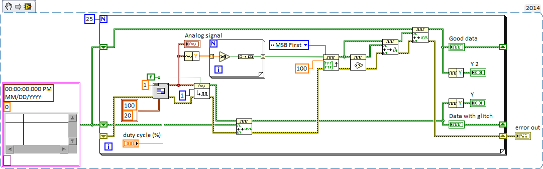
Waveforms digital output duty cycle glitches
I try to use a square wave converted to digital output to operate some solenoids but seeing some problems with the cycle on the digital waveforms. The output frequency will always be of the order of 1 Hz and duty cycle must be adjustable to integer values. I have attached a simplified below, demonstration that shows the digital/analogue output VI I used initially. the problem with this VI, is that if I choose a cycle that is not a multiple integer of my samples for waveform I get seeds. If I use the Boolean digital VI table this problem disappears in my simplified code, but in my real program the problem reappears.
This image shows the waveform analog generated as well as the digital output that results.
In the digital waveforms, you can see that the duty cycle of 50% is sometimes applied during the single loop (~.2us) instead of more than 1 sec iteration, although the curve of actual load indicated in the table at the bottom seems to suggest that LV ignores this glitch (somehow). As I said, the problem disappears if the duty cycle is an integer multiple of the sample/loop. Timing of the loop is torn apart by other e/s to 2 000 Hz/400 samples per loop and 100 Hz/20 samples per loop (large enough VI otherwise I would include it). Obviously, I could change them to get 50% as a multiple, but this does not solve the problem if user needs to adjust from there.
Can someone point me in the right direction here? I'm sure that there is a stupid/easy solution, but I can't seem to get.
Thank you!
You might try turning the inputs A and B of waveform of the VI of the digital samples append. It seems that A should be the fate of the shift register data (the original data) and B should be added (the new waveform) data anyway, at least conceptually.
Paul P.
Engineering applications
-
cDAQ-9263 modules do not allow independent generation of waveform
I have a client with a cDAQ-9178 crate with two 9263 modules. When it tries to start two independent signals on both modules build tasks, he gets an error in DAQmxWriteAnalogF64:
device cDAQ1Mod2:-50103: NI Platform Services: the specified resource is reserved. The operation could not be performed as indicated.
Extended Info:
Platform AND Services: The specified resource is reserved. The operation could not be performed as indicated.
Task name: cDAQ1Mod2AO
State code:-50103
It seems that it must be a driver bug-usually these "reserved resource" errors occur when you try to validate the task, but it comes from DAQmxWriteAnalogF64. It verifies that he can start two independent signals on two completely independent devices build tasks, but he cannot do it on two modules in his cage.
Is it a kind of witch-hunt with modules in a box? or a driver bug? He tells me that he has updated the driver until his "last from the website of OR" with no luck.
Thanks in advance!
The cDAQ-9178 has only a simple timing analog; output engine You can't have a timed analog output generators of waveforms of the task at a time. Unfortunately, the mistakes of 'the specified resource is reserved' are not more descriptive.
The call of DAQmxWriteAnalogF64 pushes the task as a 'reserve', which is where he tries to book the timing (and other resources) engine: the first task will succeed, but subsequent AO to the tasks will not be until the first has reserved resources.
The two tasks are intended to operate simultaneously at the same speed? You can put chains of two modules in the same task by using a string of physicalChannel as cDAQ1Mod1 / ao0:3, cDAQ1Mod2 / ao0:3 with DAQmxCreateAOVoltageChan.
-
How to include an additional channel in the standard waveform driver series AFG 3102
For Dennis.
I tried to copy the string. I placed the 2 chnnnels and tried to connect with various operators or similar AND SUM, FUSION, etc... but wasn't able to get both outputs simultaneously.
If by duplication, u mean something else, then please suggest me the same thing.
Thanku for your answer.
Kind regards
Charlene.
Following here.
None of these functions are useful. You just need to duplicate screws as I mentioned and that are already in your code.

All of this assumes that the instrument will allow both outputs being on at the same time. You can quickly verify this by trying to activate them manually.
-
Satellite P100-102 without digital-video output TFT-connection-Port?
Hello
We do not understand why mobile phones latest, as the Satellite P100-102 would be produced without digital-port connect TFT´s...
On the market-enduser TFTs are popular, but it is not possible to use the digital interface with the portable toshiba. We are not interested in the purchase of laptops from other manufacturers, but our time flee.
Can you give us a tip, then of the next generation Satellites with digital output to connect TFTs will reach the market?
Best regards
SaschaHello
Sorry, but I disagree with you.
Toshiba designs laptops that support the digital port (D-video output port)
Check for example the Qosmio of E, F, G series. -
Spreadsheet Numbers: how, please, can I fill a single column in a single digital series from 1400 and goes to 3000?
in the cell where 1400, replace the contents with:
= 1400 + Row)
Suppose that it is cell A2
shortcut for this:
A2 = 1400 + Row)
Select cell A2, copy
Select cells A2 at the end of the column, paste
-
I am trying to simulate a signal digital 72Hz to an external circuit. Attached below is the pattern that I use. I had to initially waveform graph to view the signal, but data types are different, so I ended up using a waveform digital chart vi. Once I run the simulation, nothing in the graph. Help, please. I use a hardware DAQ USB 6001.
BTW, I tried to create a task in the DAQ Assistant, but succeeds only when the acquisition mode has been set to 1 sample (on request). When you do what I wanted, which was a continuous sampling, an error has occurred.
Error-200077
Requested value is not a vaalue supported for this property. The value of the property may be invalid because it is in conflict with another property.
Property: SampTimingType
Requested value: sample clock
Possible values: on request
Basically, what I want is to see the place in the graph of the signal waveform and perform a signal processing.
Too bad. I already solved the problem. I used to analog rather than digital input
-
How do I configure other digital ports except port 0 of daq 6351 acquisition of digital signals
Mr President.
I can acquire digital signals using 8 lines of port 0, but I have to get the waveform Digital 24-bit. So please tell me how to configure other DIO ports so that I acquired digital signals using these DIO line also
You should be able to create a task DAQmx to read Port0, Port1 Port2. When you read the DAQmx data, you must combine the port if necessary data table.
-
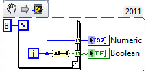
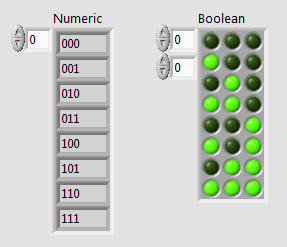
How to generate 3 Wick using digital signals
Hello
I am in the course of generations bit 3 digital using 9403 digital module and cRIO 9014.I signal must generate all combinations from 000 to 111.la so I have to give the Boolean constant either true or false 9403.I output module'm not gettimg how incrase step value of 000 001 and so on... Should I use the shift register?
I know how to use the registry to offset for integer value bt I don't hv any idea on the Boolean value.
in the hope of solution...
Here is a small example that uses the number to array of Boolean function. The digital indicator has its display of the binary value (%b) formatting.
-
NI-DAQ-200288 digital output error
Hi all
I am using Matlab control PCI-6534. In the code, I try to write not Npulse (= 3). Pulse. Data of the pulse are of size 1 X 1e5. When I try to write in the mode of generation of finite samples it generates error-200288 when you write data pulse 3rd time. 1 twice, it gives no error.
The flow of code below is 1. Open 32-bit channel to write digital data to the 10 MHz clock.
2. put sample over genration and disabel regeneration.
3 write first pulse data to buffer.
4. start the task
5 enter the number of data pulse Npulse-1 immediately
6. wait until the task is done and stop the task
CLC;
inputDATA = uint32 (100 * randn(1,1e5));
NPulse = 3;
rate = 1e7; % 10 MHzIf (libisloaded ('myni') ~ = 1).
[notfound warnings] = loadlibrary ('nicaiu.dll', 'C:\Program Files\National Instruments\NI-DAQ\DAQmx ANSI C Dev\include\NIDAQmx.h','alias','myni');
end
taskh = libpointer('voidPtrPtr',0);
DOtaskhandle = taskh;
[errCode, taskName, DOtaskhandle] = calllib ('myni', 'DAQmxCreateTask', ", DOtaskhandle);
DOtaskhandle.setdatatype ('voidPtrPtr');DAQmx_Val_ChanForAllLines = int32 (1);
DAQmx_Val_Rising = int32 (10280);
DAQmx_Val_GroupByChannel = uint32 (0);DAQmx_Val_FiniteSamps = int32 (10178);
DAQmx_Val_GroupByChannel = uint32 (0);
DAQmx_Val_DoNotAllowRegen = int32 (10158);
numSampsPerChannelWritten = libpointer('int32Ptr',0);
reserved = libpointer ('uint32Ptr', []);
data2 = libpointer ('uint32Ptr', inputDATA);
sampsPerChanToWrite = uint64 (numel (inputDATA));
inDataLen = uint32 (numel (inputDATA));
sperchan = uint32 (inDataLen);[errCode, lineNames, nameoflines] = calllib ('myni', 'DAQmxCreateDOChan', DOtaskhandle, [' Dev1/port3 Dev1/port1, port2/Dev1, Dev1/port0], ", DAQmx_Val_ChanForAllLines);
[errCode, clockType] is calllib('myni','DAQmxCfgSampClkTiming',DOtaskhandle,'OnboardClock',rate,DAQmx_Val_Rising,DAQmx_Val_FiniteSamps,sampsPerChanToWrite);
If (errCode ~ = 0)
errMessage = "Error during clock setting";
calllib ('myni', 'DAQmxStopTask', DOtaskhandle);
calllib ('myni', 'DAQmxClearTask', DOtaskhandle);
return;
end
[errCode] is calllib ('myni', 'DAQmxSetWriteRegenMode', DOtaskhandle, DAQmx_Val_DoNotAllowRegen);.[errCode, writeArray, numSampsPerChan, zz] = calllib ('myni', 'DAQmxWriteDigitalU32', DOtaskhandle, sperchan, 0, double (10), DAQmx_Val_GroupByChannel, data2, numSampsPerChannelWritten, reserved);
If (errCode ~ = 0)
errMessage = "Error when writing the data of Stimulation" 1;
calllib ('myni', 'DAQmxStopTask', DOtaskhandle);
calllib ('myni', 'DAQmxClearTask', DOtaskhandle);
DISP (errMessage);
return;
end[errCode] = calllib ('myni', 'DAQmxStartTask', DOtaskhandle);
if(errCode~=0)
errMessage is ('error in startup DAQmx task');.
calllib ('myni', 'DAQmxStopTask', DOtaskhandle);
calllib ('myni', 'DAQmxClearTask', DOtaskhandle);
DISP (errMessage);
return;
end
for i = 1:NPulse - 1
[errCode, writeArray, numSampsPerChan, zz] = calllib ('myni', 'DAQmxWriteDigitalU32', DOtaskhandle, sperchan, 0, double (10), DAQmx_Val_GroupByChannel, data2, numSampsPerChannelWritten, reserved);
% If (errCode ~ = 0)
% errMessage = "Error when writing the data of Stimulation";
% calllib ('myni', 'DAQmxStopTask', DOtaskhandle);
% calllib ('myni', 'DAQmxClearTask', DOtaskhandle);
disp (errMessage);
% return;
end %
endIstaskDone = libpointer ('voidPtr', logical (0));
[A11 A21 A31] is calllib ('myni', 'DAQmxIsTaskDone', DOtaskhandle, IstaskDone);.while(A31==false)
[A11 A21 A31] is calllib ('myni', 'DAQmxIsTaskDone', DOtaskhandle, IstaskDone);.
endcalllib ('myni', 'DAQmxStopTask', DOtaskhandle);
calllib ('myni', 'DAQmxClearTask', DOtaskhandle);Can anyone help me please with this code. Is there some step I'm missing or not setting any parameter not?
Thank you
Vani
Take a look at this:
Why do I get error-200288?
http://digital.NI.com/public.nsf/allkb/BFCE83133C0ECAD786256E6000814B68?OpenDocument
Using traditional DAQ or DAQmx?
-
Access waveform data passed in a DLL
Hello
I'm working on a LabVIEW application that processes the continuous stream, 2 ms/s, 32 analog input channels, each channel. This application has a DLL built in order to improve the table great handling performance in LabVIEW. Initially, I fed the DLL with a double 2D array returned by DAQmx Read VI and worked on a controller embedded high performance. However, the new requirement is, I need to treat timestamps as well as each Read call to HAVE him, and that's why I need to feed the DLL with the waveform data returned by DAQmx Read. Output waveform contains the timestamps I need.
The problem is, I don't see an easy way to access the data of waveform within the DLL (developed using Visual Studio C++). The type of waveform data seems to be a C++ class, and who looks like I need to add a considerable amount of code to retrieve the data within the class of waveform.
My question is, LabVIEW naturally does support access to waveform data in a DLL and if there are examples of code? I understand, I can you can also process outside the DLL waveform data and feed the DLL with the array element in the waveform data. However, I have concerns about whether if performance will be significantly affected.
Thank you!
Donghui Yin
Doy says:
Sorry for the incomplete design details. If you are interested, I have used high cards, not PXI. This is why I don't have a problem of bandwidth PXI. Special assistance, I need right now is the note, 'External Code in LabVIEW using' manual on Page 2-7:
"Note waveforms, digital signals and digital tables can be passed through shared
"libraries, but access to the data inside shared libraries is not supported at this time."Thank you.
I think that the text is clear enough! There is no documented API for access to international it data waveform within an external code module. The generated data type the node in library call for such a parameter is HWAVE or something, indicating that it is an opaque handle whose implementation details are deprived of LabVIEW. Since there is no documented API for access to her international of such data there is simply no way to access it.
And I didn't know all the functions that are exported in the LabVIEW executable that I could easily connect with the waveform dataype. Even if I had, we still do not know the prototype (aka list of parameters and types) of these functions.
Your only viable solution is to work with the data types supported. Your C code, or possibly the LabVIEW (table handles) native data type, either passing data in table C. else pointer would require reverse engineering of disassembly, a legally questionable approach, but also a lot of your time. And everything you would find this way I would be very hesitant to use in what feels, walks or crawls like a real-world application, since you can't be sure that your conclusions will work for any situation. It is also likely that your results will depend on some attributes may change between versions of LabVIEW.
-
Assistance needed: average N amount of waveforms
Hello
First of all, I have my apologies to re-post this topic, but I didn't help I need the last time I asked, probably because I didn't clearly what my problem was. So here goes...
What I need is for some genius here to show me how the average amount of N of waveforms. I am able fluctuations of current in a specific time window (this depends on the amount of samples and of course sampling rate that I use).
Currently, I record quantity N of waveforms (time series), but what I want to do is only to record an average undulating, e.g. n1 + n2 + n3/N (N = 3).
I gave it a go using a loop, but it didn't give me the results I want (I know what's the problem with him, but don't know how to produce the waveform on the average).
In summary to be as clear as I can be,
(1) I am recording N waveforms of the DAQ Assistant
(2) I want to collect in a queue and then take the average of the N wave
(3) save the medium wave to my function write.
Attached are 2 versions of LabView to my project.
I would really get this spot and exploit this week if possible and would be very grateful for help in changing my vi.
Thank you very much for reading!
12.
Maybe you are looking for
-
noticed the same problem, my friend had 2 months in hardware of the iphone 6!
Hello I use the iphone 6, which is out of the now (india) warranty period. I noticed a problem on the screen detaches from the main frame around one of the edges. It's the same problem happened to one of my friends who ultimately involving more areas
-
When you search for available updates on the update site, I receive the 0x800A0046 error.
HELP 0X800A0046
-
Original title: substitute .img .iso I try to install PES 2011. I discovered that I should somehow 1 20 file .img .iso file. How can I do this?
-
I have windows Windows vista 32 does not allow me to connect to a laptop than high Dlink wireless router has wireless built into it. Whenever I try to connect a pop-up window appears telling me to start again or try another connection WiFi
-
Remove Office Add-ins - Windows does not recognize my administrator status
Even if I'm already logged as an administrator, I get the message "You must be an administrator to remove these add-ins" when trying (in vain) remove an add-in