Photo labview
Hi evryone,
Im a beginner with Labview you know I can see a picture in my executable file. In normal VI I see, but when I debug him is lost. Ive tried to find some information on this problem but I've found nothing. Can you help me to smb. ?
THX tom
Dennis is right, you should use the 'path of this screw' primitive and change the path in regards to your insurance VI works no matter where the application runs.
Tags: NI Software
Similar Questions
-
Vision and Motion screws missing
Hello
I have installed (in order):
-LabVIEW 2013 PDS 64 bit
-Vision Development Module 2011 64 bit
-LabVIEW PDS 2011
The range of Vision and movement is visible in 2011 and 2013. But in 2013, the palette is empty.
I could get this to work?
Thank you
Hi Marvin,.
in your case applies the first photo: LabVIEW vs VISION!
And it shows it clearly: you can use any version VISION from2011 with LabVIEW2011VISION.
But to use LabVIEW2013 , you need to install VISION2013 (or newer).
-
Hello
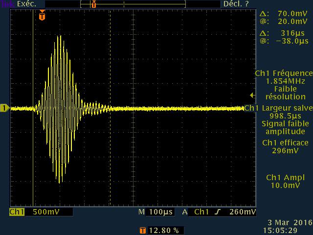
I'm doing the acquisition and processing of an oscilloscope, signal
and I would like to know if I could have the photo goes on the oscilloscope on labview
"without going through the graph of the function" the exact image on my oscillocope: see local closed.
-
Allocation of memory ring LabVIEW animation photo
I create an animation in labview, I have 1,000 images that I need to go, I use a pict ring and flipping through images... problem is after loading about 200 images (they are 20 k each) my computer to throw in the towel, the RAM is full virtual RAM could be full... I wonder if there is a work around around that? Any kind of way to manipulate memory so I can finish? Maybe it's more of a thing of computer a thing of LabVIEW... I thought, if I increase my virtual memory of slots "a lot" and say LabVIEW is not to use e RAM just use virtual memory that maybe I would be able to continue, but I don't know if this is possible or how to make it... any suggestions or advice?
Thank you very much!
PS - I realize that there are other programs that are well adapted to this and what LabVIEW is really not the animation software, but I use LabVIEW for this and I am lookin to get advice whether or not this task is possible in LabVIEW. Thank you.
I would advise not to use the ring of the photo, if it is because it is not very convenient.
You can use the image control, allowing you to read and display the PNG images one after the other (using the screws in the palette of the image) and here you have two options:
- Read the files one at a time. Could be a problem if you do it quickly and repeatedly, it will solve problems of memory, you may have.
- Read files at once and keep them in memory. Note that the image control is not any compression, so the actual size of an image in RAM would be PIXELS x 3 bytes (or x 1 byte and a bit, if you have a color depth of 8 bits), so the amount of RAM depends on the size of the image. For a 200 x 200 image, this should be 120 KB, assuming that I did my calculations correctly.
-
How to display an object mesh continually update with the Labview 3D photo object
I have a stream of update permanently of 3D images that can be represented in a mesh (a film in 3D if you want). I want to display in the 3D image object so that whenever I acquire a new 3D image that it is displayed. Examples are rare, and I couldn't find anything that dealt with this particular issue.
Currently (in a FOR/loop WHILE) for each iteration I create an object of the scene, set the geometry as an object mesh newly created, set the texture and it wire eventually to the 3D image. This implementation seems a memory leak (Task Manager shows permanently increases the used memory and processing speed will eventually drop). I guess that's because I recreate the object for each iteration. Problem is, I can't find something that would let me release/delete the object once I'm done with the framework. All the examples I found only deal with the creation of the 3D object once and manipulating.
What is the appropriate way to code this?
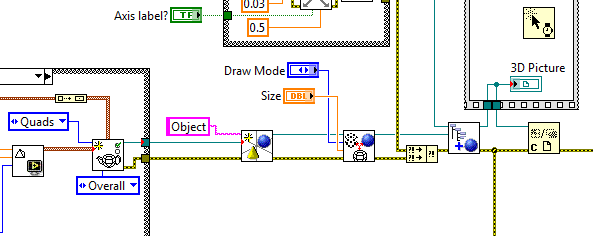
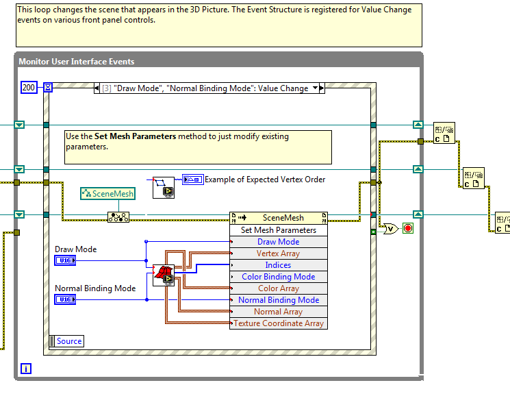
You just need to use the "narrow" VI on reference photo 3D like this code below. It runs inside the loop.
Now, if you're dealing with the mesh, then you should use the set the mesh to change the points inside the loop and then just close the reference after the code is done. Look at this code below. The trick is to recover the object using Typecast (to more specific reference VI) reference.
Also, look at examples of shipping to:
C:\nivs_dev\2013\InstallTo\ProgramFiles\National Instruments\LabVIEW\examples\picture\3D Picture Control
and especially the with Meshes.vi.
-
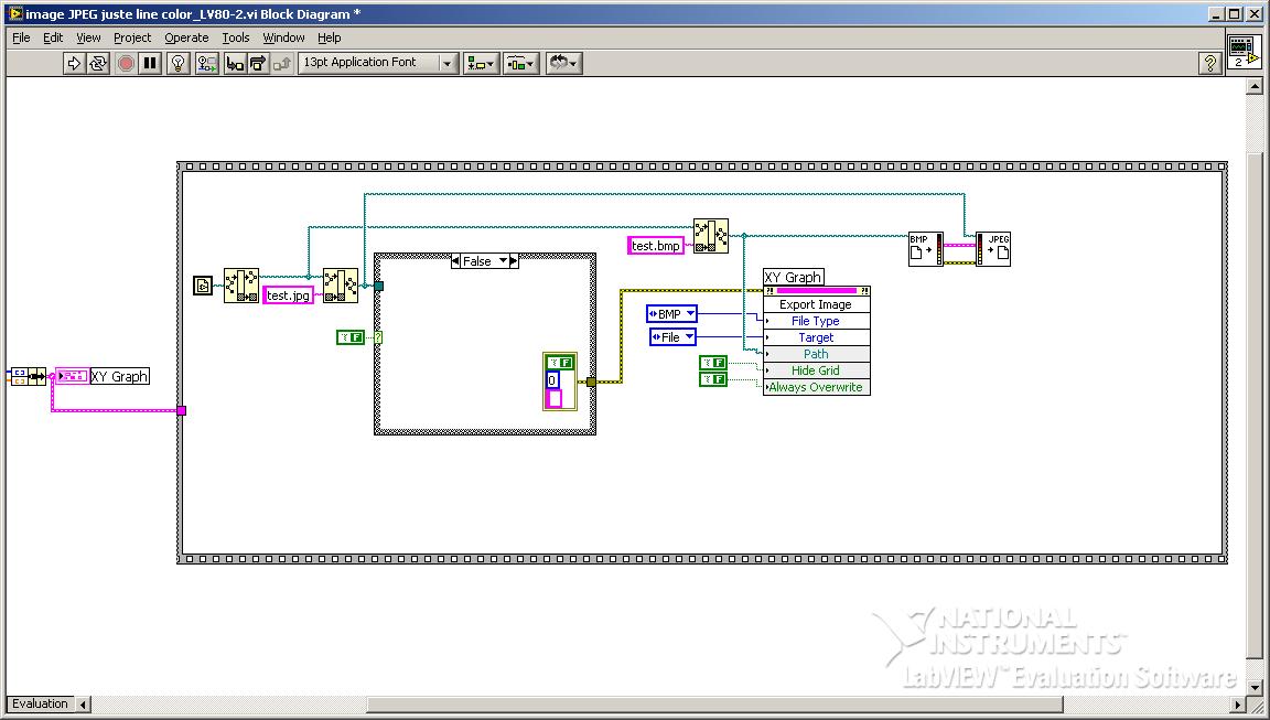
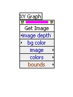
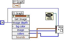
How to export the photo graph XY in Clipboard (or file) with labview 6i
Hello
I would like to export graphic image XY in Clipboard (or file) to insert it into a word document using labview 6i
I found the example for labview 8 using invokenode, but not with labview 6i
But this invokenode does not exist in labview 6i: here's what I found in labview 6i
Anyone know how to use this one?
Thanks in advance
Wow, had not launched LV6i in a while, never realized how much I rely on the automatic selection of the tool.
You can wire that call the node directly in the 'write to JPEG File.vi'
-
LabVIEW 8.6: photo 3D control command
Hello Tom,
This was reported to our R & D Department (AUTO ID #146558) for further investigations. There is no work around yet displayed.
You can send your local branch with this reference and find out if there is no development in the near future and look out for a fix with the next version of LabVIEW.
Thank you very much for your comments! It is much appreciated!
Kind regards
Michael S.
Technical sales engineer
NEITHER UK & Ireland -
Hello
I use the XY graph to display GPS data, XY graph also displays a map that is be pre-processed using vision functions to display a correct part of the image data, climb the ladder etc.
Everything works fine, but the average standard conversion
long (25 ms). He becomes hostile user, when all scales / relocation of the XY graph introduces a delay.
IMAQ vision preprocessing takes about 25ms too, as well as other calculations, the user's response is about 60ms, and it's just so - so to use.
I hope to cut treatment time here, because he just flattening a table.
I started to do my own IMAQImage2LVPic function, but little success, because I do not understand the Image of the LVPicture format, I get distorted images, violations of memory, and it becomes frustrating.
The structure of the memory of the LVPicture would be nice to know. Help, please.
Rather than drawing in the PlotImage of the XY graph, have you tried to make the transparent XY graph (which includes both the background of the chart and also control encompassing) and placing it in front of a screen of Vision? Then, you will not need conversion. I have not tried, so I don't know if there may be problems with the speed of drawing, flicker or aliasing, but it might be interesting to try.
-
Hallo
I got a picture of some VI´s, I would seem like the name, can´t to find it anywhere

Best wishes
CBJ
-
Display ActiveX Image on LabVIEW front [method returns 'handler' (stdole - IPictureDisp. (Photo)]
-
using the structure of the event in the LabVIEW classes
Hello
I'm new in the use of LabVIEW classes, so don't know much how I can use them.
In my main program, I have clusters with five elements in each. The elements are controls two States and in some groups, there are three States controls. The user will press the buttons (controls), and different things will happen. In my first program were I not using classes, I had a structure of the event and the controls were cases of event in the structure.
Is it possible to somehow use an event of cases in one of the methods that is created in the classes, so that say, that's not in the main program?
I have attached two photos: I wanted to have a structure of the event in servoTouchEvent (in left.tri.lvclass) who is a child.
Let me know if my explanation is not clear.
Grateful for the help!
Hello
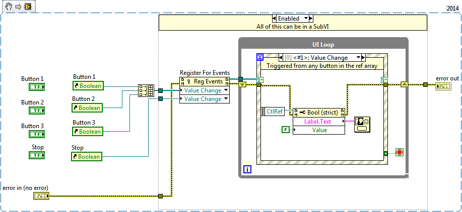
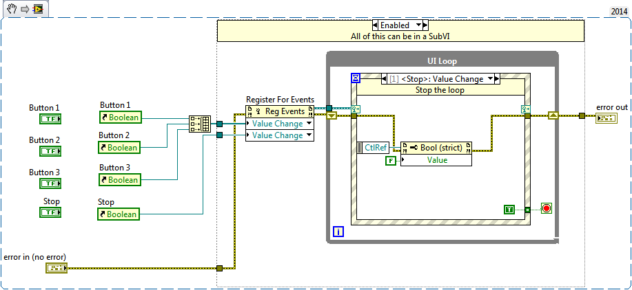
Yes, you can have a structure of the event in a Subvi rather in your main VI of top-level UI. The trick is to use the 'Save for events' and passing in references to orders that you want to have the event trigger structure for. The refnum output since the function is entered in the terminal of dynamic event of the structure of the event who could live in a Subvi. You can add instances of event where you will see these control events as dynamic events then you can do something with. These excerpts from shows all the code in a simple diagram, but the stuff in the structure of disable diagram could easily transformed into a Subvi:
All this can be done without classes. What will buy classes you include the ability to encapsulate your screws and also perform different code based on what object on the hierarchy of the parent-child classes is on a wire. If the behavior of your code is different between 2-3 State and controls (which I do not know what state controls 3 you are referring), you can take advantage of the classes.
-
How to read the Serial Arduino data using labview VISA?
Hi =). Im a beginner work reading data series from an arduino but im facing... Lets do it step by step
I built a voltage divider circuit which gives from output
from 0 to 5V. The output of this circuit is sent to a 0 analog input pin
of a Committee of Arduino Duemilanove.(1) Firstly, I connected the cable to connect to my laptop USB the Arduino.
(2) I went to start-> control
Control Panel-> system-> hardware-> Device Manager. Check the Ports (COM
& LPT). In my laptop I can see USB Serial Port (COM4). Now I know only in
LabVIEW that I must read the data series COM 4.(3) to the side of the arduino, here's the code to read changes in voltage
entered to analog pin 0. The last line of 'delay' determines the sampling
Rate of how we want to taste the output of the voltage divider:int potPin = 0; Select the input pin for the output of the voltage divider
int val = 0; variable to store the value from the probevoid setup()
{
Serial.begin(9600) (9600); Opens the serial port, establishes the rate of 9600 bps data
}void loop() {}
Val = analogRead (potPin); read the value of the voltage divider
Serial.println (Val);
Delay (10);
}I slightly modified the basis series reading writing VI... I have
attached the block schema used with comments. Basically, I tried to read
data series, divide by 1023 and multiply by 5 to graphic voltage
variations of the voltage divider circuit. But Im not getting
the correct voltage output values. The value of the tension just keeps go
0 and coming again, as shown in the photo.Could you guys please guide me on what went wrong?
Thank you!
-you read the data, even if there is no data on the port. If 0 bytes are read => «»
-in the case of false, you resources VISA wired for the output of channel tunnel?
-There is no close VISA at the end of the VI resources
-you're not a loop this VI reading bytes
I added an addaption of your VI that you should give a try maybe

-
updated 2009 LabVIEW Mathscript
Hello
I developed an application in LabVIEW 8.6 who
contains a large MathScript node. It's time to upgrade to LabVIEW 2009
and I am facing problems in that. I have the Mathscript RT Module
installed and enabled on my computer.I want to emphasize that
the application works perfectly at 8.6. After the first performance in
version 2009, I got 2 errors:-90031: "unknown output."
variable. The variable is a string. He showed up in a red dot
(see photo). I've never seen this before red dot...another
error in another node:-20104: input parameter have at least a NaN
element. What is an element of NaN? This error occurs in a line that looks like
as A = median (B) where B is a vector line.also in this second
node, I have a lot of output shown in the red dots, the string variables
outputs and some double precision as well.What
are the requirements to upgrade to LabVIEW 2009, insofar the MathScript
is concerned? There are issues to be addressed? major changes, I should
Be aware of?Thank you very much
Sam
Hi Sam,
You can define variables by their wiring as inputs or by setting them in the script of the node.
If your solution is still available in 2009. In fact, this looks like the right solution to get the behavior you're looking. I think that the reason that it does not work is that there is still some output variables that need to have your solution that are applied to them. These output variables are currently not be wired in the shift registers MathScript node and are only defined in the case of statements which are false, when your code is running. So, if wire you these variables in the MathScript node, the errors should go away and you will not see the default values.
Initialization of variables in the upper part of the MathScript is another way to get rid of the error. However, it seems that this is not the best solution in your case because you want the variables to receive the same value they had at a previous time, that run MathScript node. The best way to do is with registered SHIFT wired as inputs to the node.
The reason for this change in behavior between 8.6 and 2009 is indeed to help users find bugs or logical errors with their code. The new behavior makes it less likely that downstream from the MathScript node code tries to use an output that has an invalid value (by default).
I hope that this explanation makes things a little clearer.
Thank you
jattas
-
Image Matching with Labview or model
Hi all!
I am currently implementing a picture matching algorithm on two .png images (let's call them model and Photo).
The idea is that the template contains an examply of which must be shown in a certain part of the picture.
Model and photography have sizes of different images.
What we want to achieve is:
1 find the return on investment in the Photo where the model is likely to be found
2. compare the KING with the real model
3. get a percentage of similarity (e.g. 90% similar-> specific Match, 70 to 89 %-> accordingly Match Possible, <70%similar -="">not a match)
Do you have ideas on how we might put implement this?
We currently use LABView 2015 SP1 - 32 bit with the add-on of the Vision
We had to use a modified version of the model Inspection.vi Golden (can be found) but are blocked because the IMAQ compare continues Golden Template Module return the error message attached to this post.
Any comment on the possible debug is also welcome!
Thank you!
A model is *.png with info vision (for example, settings, info, etc.). You must create the model using model editor which should be installed and accessible from the start menu.
-
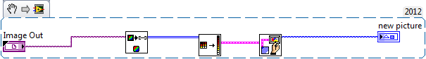
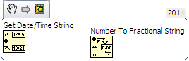
change, step set name definitely Labview Testand API
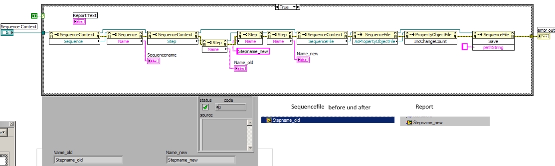
Hi, I can change a stepname to "run selected" steps in a VI, but it does not change at all times. The new name in the report file, but the old stage name stays the sequencefile. I save the sequencefile in VI and to see that it was recorded at the time but it dosnt take the new stepname in the seuencefile. Is there a possibility of othe to change the stepname permanently?
Here is a photo of the façade, blockdiagram, sequencefile before and after and the report. I use Labview 2012 32 bit with Teststand 2012.
I have not tested but you should know what you're doing after you rename step: use the SequenceFile reference.
Identify the step from this reference (SequenceFile-> sequence-> step) and make the name change.
Norbert
Maybe you are looking for
-
I can't get to the homepage on my iPad Air. Isn't he dead?
-
How to erase a hard drive on photosmart c410a?
I replace my photosmart c410a. I want to make sure no data on it before I donate to a charity. is there a hard drive I need to delete? If so, how? I can't believe the amount of time, I've been running around this issue. Thank you
-
It is safe for me to delete the contents of this folder [C:\Users\Maggiol\AppData\Local\Microsoft\Windows\Temporary Internet Files\Content.IE5\TDQ4BF1R] It's got a virus [msa.exe], it was the creation of the internet Temp files in this folder. I was
-
How can I remove an OEM Partition?
I use my old hard drive as an external drive with a speaker. I was able to remove the 2 partitions (1 had the OS) very well. But there is now a left of the partition that I can't remove. It says 63MB, healthy (OEM Partition). When I right-click,
-
Classic BlackBerry BB classic: can not load completely while the power is on
Madam/Sir, I just bought a classic BlackBerry Q20. My problems are: 1. I can't fully charge the unit while it is on. If it is enabled, the battery power stops at 60%, no other. 2. If I load normal when the unit is off, Yes, it will charge up to 100%