Card bad voltage outputs data acquisition / cut off voltage
Hello
I use a 6713 PCI and PCI MIO 16E1 and have a very strange problem: when I try out a voltage using LabView, I get instead of the voltage, a tension cut with a high unstable phase. Basically, all right, as long as my blood pressure is below 0.3V. All is well here, high level is stable, precise curve shape. But as soon as it exceeds 0.3 V, it is cut and the tension starts to drift. I have attached a drawing of the problem in this post.
The system worked very well, but a week ago, the problem appeared. First he went again, but now he reappeared. The first attempt to define a certain tension might work, but already for the next pulse the problem occurs. Now she even work correctly once. Reboot etc did not help.
The funny thing is, however, the same PC has two features listed above. I only and never used the PCI6713. When the problem occurred, I tried to move to the MIO 16E1 but it shows the same thing! Exactly the same problem here! I unplugged all the wires to the cards and it still does not work. Anyone here with an advisor?
Thank you!
Mike
I was able the output voltage with a scope with 1 MOhm input impedance. But I found the problem by chance now! We got a whole batch of defective cables BNC! I already suspected the cable and tried different cables, about the same result. Then somehow, as I wrote, the problem disappeared once. Now, I used another type of cable to test the unit and it worked! So I checked the other BNC cables, and some of them seem to have a shortage between the mass and the Center, but in a way it produces sort of a junction diode (probably because of a layer of oxide somewhere). When I shook the cable suddenly I could measure a low impedance between the mass and the Center, but only for milliseconds, just like a bad contact.
Really weired! But thanks for the help!
Tags: NI Hardware
Similar Questions
-
Hello guys,.
I have a general question regarding the units of packaging such as the USB-9263 analog output signal. If I can use it instead of data acquisition to provide an analog voltage output?
Thank you
ELA
Yes, the 9263 can provide 4 output channels analog voltage (+/-10 v range) with up to 1mA of current drive. Looks like: it refers to the short circuit of conditioning of signals and some protection against overvoltage. Link below is the User Guide:
http://www.NI.com/PDF/manuals/372406b.PDF
-AK2DM
-
BNC-2110, 6023E PCI card and Labview V9.0: sensitivity of data acquisition (change more little detectable voltage) is 0.002V
Hi, I use the software/hardware above to read a voltage of a potentiostat world Precision Instruments No..
I'm trying to record changes in voltage as low as 0.0003V but using the wizard DAQ, I seem to be limited to a sensitivity of 0.002V. This is the limit of real sensitivity or have I missed something?
Any help would be greatly appreciated.
Hi DCAM77,
Thanks for joining the forums!

The PCI or 6023E has a 12-bit ADC. In other words, it can make the difference between 4096 (2 ^ 12) different levels within the range of cards. The card you have has a selectable range by ± 10 V, ± 5 V, ± 500 mV or ±50 mV software.
This means that the minimum detectable variation will be 4 mV, 20 mV, 244 µV or 24, depending on the chosen range µV.
You should be able to use the ± 500 mV or ±50 mV to get the least significant bit (LSB) value, you need, even if it means that your signal is located between these values. If not, then you need to consider other materials to the application, or the addition of external circuits across the signal.
-
We send 5v data acquisition using a voltage generator. Hook us it up to a voltmeter and see 5V. When connect us the generator voltage to a valve "normally open" parker, the voltmeter indicates .14V. It seems that when we connect the two sons of the valve for the voltage generator, the son act as pattern. We want to control the voltage flowing to tap through Labview. We checked the wires to the valve and they work very well, because if we send a constant 5V since the acquisition of data and put ashore, she, the voltmeter indicates 5V. Someone knows why the son act as pattern and low blood to .14V?
nsatpute wrote:
Our data acquisition is NI USB-6259. The valve requires only a 5V max and our DAQ provides up to 5V. However, after connecting the valve to the acquisition of data, the grave tension to almost 0. We start from the principle that the son somehow act as the reason, but we are not sure if this is the case.
The question here is not how much voltage the valve wants, it's the current needs of the valve. The 6259 can put only 5mA via an analog output. Your very likely tap needs much more than that. If you need to add in an amplifier circuit that can supply more current to operate your faucet.
-
How to get to multiple data acquisition voltage signals
Hi guys,.
I have to run an event for children to play with different types of energy production, so we have a wind turbine, solar panel and a generator. I have all of them connected to the ports of entry of the C USB DAQ series, I can't seem to find a way to make data acquisition out all three voltages simultaneously, the DAQ assistant in labview won't do it, AFAIK. I need all the outputs of all so that the children can see the reknewables plus and then complete the lack to win with the "power station" generator, so I need them all running at the same time. I had a quick glance at similar problems, but I don't see how they are relatable to my case.
I have attached the vi below, thanks for your help.
Amy
DAQ Assistant allows multiple entries of tension. When the analog channel selection hold down the SHIFT key and then select as many channels available, you want.
-
How to find the time between two channels of entry in the data acquisition card or pci 6036
Hello
I read a lot-related posts on the simultaneous measurement of two input voltage of similar channels in map data acquisition. I know that the best material is "simultaneous measurments of the Series DAQ cards" but I only pci data acquisition card 6036 and I try to understand what is the time between the reading of the two channels . This period is always constant? (must it rely on a voltage (amplitude, frequency, waveform..). I send the sine wave (s) to the two channels and read the values of V, if they read the same value, the difference should always be zero but I get-0,002 to 0.002 Volt difference (I must find a way to convert it in time). A screenshot of my VI is attached. I wonder how I can accurately measure the time delay between the channel.
I am open to any suggestion, my final goal to read exactly two channels at the same time ((ou connaître le délai exact donc je peux correspondre les données correspondantes étant donné le temps de retard))
Hi spinup,
better you should post your question in the forum of LabVIEW, LabWindows/CVI is used

Good luck.
-
I am building a system and I need to help experts to choose the data acquisition card.
Hello world
I am currently working on a design project I need to take a data acquisition card that responds to the output of the amplifier. I'll build a force detection system which I have taken the following as detector and amplifier:
http://content.Honeywell.com/sensing/Sensotec/pdf_catalog08/008834-1-EN_Model_UV%20Bridge.PDF
http://content.Honeywell.com/sensing/Sensotec/pdf_catalog08/008638-1-EN_Model_53.PDF
Please recommend me which data acquisition card I could take. The only requirement I ask is to have less than 0.1% global uncertainty.
Thanks for anyone who can help
Since your amp has - 3db at 7 kHz and you need only 10 bits 0.1% will do almost any card with. USB-6009 is the lower end. USB-6210 the next step.
Then take a look at some other boundary conditions: do you need it calibrated? (Is there a QM adj. who could ask questions?) Space?, EMC/noise, entry, differential
Take a look at the USB-9237 with a conditioner bridge construction...
-
Data acquisition in LabView for other suppliers DAQ cards that NEITHER
Hello
I am a beginner in LabView programming. I have a 32 channels base PCI card DAQ (i.e. PCI-1602 of the manufacturer, ICPDAS) and I want it to interface with Labview 8.5.
So how cards DAQ in Labview 8.5, which are manufactured by other suppliers that NEITHER? Should I DAQmx (or some other driver) for that?
What are the other drivers/components required to access of data PCI-1602 (device) of LabView 8.5 acquisition card?
(1602-PCI card driver are installed in my win XP and dispalyed in Device Manager).
Please provide some tutorial above mentioned the problem to interface.
Please guide me in this regard. Thank you
Waqar123 wrote:
Hello
I am a beginner in LabView programming. I have a 32 channels base PCI card DAQ (i.e. PCI-1602 of the manufacturer, ICPDAS) and I want it to interface with Labview 8.5.
So how cards DAQ in Labview 8.5, which are manufactured by other suppliers that NEITHER? Should I DAQmx (or some other driver) for that? You will need the drivers from the manufacturer, of the Board of Directors. In your case, "ICPDAS.
What are the other drivers/components required to access of data PCI-1602 (device) of LabView 8.5 acquisition card? Same as above.
(1602-PCI card driver are installed in my win XP and dispalyed in Device Manager). Ok. Then take you care of my 2 answers above.
Please provide some tutorial above mentioned the problem to interface. To learn more about LabVIEW, I suggest that you try to watch some of these tutorials.
Please guide me in this regard. Thank you
According to what you do with the DAQ cards, they can do the job however, from experience, there are some functions that I could achieve with the cards NOR that I couldn't with 3rd-party maufacturers. This does not mean that this is your case. However, it is worth noting that it took me a while to understand why the code has worked with a single data acquisition card (NOR) but not another (Non-OR).
The drivers that you have installed may or may not include examples and code in VI. They may be DLL. If this is the case, you can write LabVIEW "Wrappers" around these functions, as it will simplify your life. If the drivers are in the form of DLLs, and there are no examples of LabvIEW or available VI, you must read on node library function call.
R
-
How can I know how much memory is on my card data acquisition OR 6133?
I have a NI 6133 data acquisition card, but I don't know if this is the model megaechantillons 16 or 32. How will I know?
Thank you
Kevin Brown
Hey Kevin,
You should be able to find it by reading the attribute Input.OnbrdBufSize (property node DAQmx buffer in LV, DAQmxGetBufInputOnbrdSize in the C API). To do this, you will need to create a task to HAVE.
Dan
-
How to change the accuracy of output waveform and spreadsheet graph data acquisition
See attached vi, data acquisition connects to a waveform graph in a spreadsheet. I want to change the precision of the output of Wizard DAQ 6 decimal places with 2 decimals, but everywhere I looked on the DAQ assistant, I can't find a control accuracy. I missed something? What is the elegant way to do this?
Thank you.

Hello sunflower.
This seems related to this question...
Why do you want to change the output of the DAQ assistant?
Should not change the precision of the creation of the worksheet? To do, simply give a few parameters for the functions "to the string conversion..."
Outside the file save all the other screen precision parameters are just cosmetic measures!
-
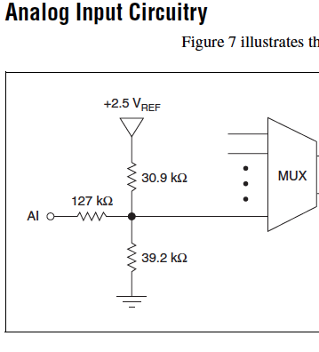
Cut-off for the 6008 analog input voltage
I am using the analog inputs NI USB-6008. The specification says they have a 144 k ohms input impedance. But it does not say what is the cut-off voltage. If you leave a disconnected and measure the voltage you will get 1.4 volts. So I guess it's the cut-off voltage, but it is not spec'd.
Someone agree that these Amnesty International isn't terminatied by 144 k - ohms to 1.4V? Is this in the documentation somewhere?
Figure 7 on page 16 of the NI USB-6008/6009 User Guide and specifications shows the strange input of this unit circuit.
Lynn
-
Card FPGA and data acquisition synchronization
Hi, we are control and data acquisition of several hardware devices (including Photodetectors and translational stages). Until last week, we used all the controls and acquisition using a PCIe-7852R FPGA board. However, we decided to move the acquisition part to a PCIe 6363 DAQ card to improve the sharpness of the tension. During the test, I found that the internal clocks in the FPGA and the DAQ cards are slightly inconsistent (not just a phase delay, but a difference in the period).
I know because I have generated a square wave (period = 20) using the FPGA and gains using the data acquisition card (at a rate of 200 kHz, that is, 1 taste every 5). I have observed acquired place shifts 5 every 5 seconds approximately. Such a change does not occur if the production and acquisition is done using the same Board. Therefore, the only explanation is that the data acquisition and FPGA cards clock frequencies are different. According to my calculations, the percentage difference between their time clock must be 5/5 s = 0.0001%.
Therefore, I wonder if there is anyway to synchronize clocks between them. Or, is it possible that I can drive the FPGA clock-based DAQ hardware, or vice versa? Also, please let me know if there is something trivial as I fix.
Thank you very much.
Kind regards
Varun
Hi Varun,
my post was only one solution...
Your data acquisition card may take an entry to control sampling of trigger. In this mode, samples draw on a rising edge of the external clock signal. As long as you stay within the limits of the DAQ (100 MHz for your card) material sampling works perfectly. There are even examples coming with LabVIEW explaining how to program your data acquisition card...
This mode use you your FPGA as clock source sampling for data acquisition. Both will run on the FPGA clock in sync. When the FPGA is a bit out of 40 MHz, so it won't matter because both devices are triggered on the same clock signal...
-
Captivate output 9: the legend text is cut off
Hello
I publish a course "for devices", a sensitive project. In some cases, my text on screen, placed in the text of the legend, is cut according to the size of the viewport. I hope that the text would rather than cut across. Regardless of the browser or the device - is the same. On each of the three sizes different default (from office, portrait of mobile tablet portrait), I fixed the text to fit. In the view of the office, I had my bounding box where I want and say that the font size is 24. According to the portrait of Tablet, I have slightly modified the framework encompassing and also changed the font size, let's say 16.
If a browser window is between one of these formats, the text is truncated and sometimes words are missing or cut off showing only a part of the letters. I looked on the blogs and I googled all out.
Does anyone else have this problem? Do I need to add provisions to display additional window for these intermediate sizes in order to minimize the probability of that happening? Or is it a setting I'm missing? I'm doing something wrong or is this a bug?

Thank you!
You must DESELECT Autosize captions!
With respect to the position properties, I would set the width in % and the height to Auto. Which should force the fixed aspect ratio.
-
You make it very, very difficult to communicate! Transcript had cut off when it was supposed to be a printed and never received after you had paid!
< deleted by the moderator >
Hello
You will need to contact support by calling/chat for this request.
* Be sure to stay connected with your Adobe ID before accessing the link above *.
Kind regards
Sheena
-
motion control for vertical actuator and data acquisition
Hello
I am a researcher (a branch of civil engineering) geotechnical engineering and I have very little knowledge about the acquisition of control and data motion, so would need a lot of help from the experts OR. I have only knowledge base on these 2 aspects based on my reading of some materials on the Web site of NOR and youtube videos, so I hope that you bare with me
. Here are my questions:I am trying to build an actuator which will be used to push a probe (a penetrometer with a load cell to measure the resistance of a soil sample), resembling the concept, photography in the attached file. I need to have these criteria for my system:
(1) actuator, which can push the probe at speeds between 0.01 mm/s - 300 mm/s with precision and move the probe cyclically (upwards and downwards) in the vertical direction
(2) load expected on the probe into the ground range: 0.02kN - 6 kN.
(3) necessary to get the load cell load data and the speed of the probe.4) able to control the actuator to a PC (speed and posotion) and monitor data from transducers and data log time even the transducers.
Guess my beginners is that I will need:
For orders:
(1) software - LabVIEW and NOR-motion assistant(2) controller - NI PCI-7342
(3) driver/amplifier - analogue servo AKD Drive
(4) motor - motor brushless servo AKM
For the acquisition:
(1) software - based LabVIEW development systems(2) amplifiers or other device - no idea what type on the conditioning of signals
(3) data acquisition device - no idea what type
Since I'm a beginner, is - that someone might recommend components (hardware and software) for the control and data acquisition. I'm on a tight budget, so I thankful if someone could help me to recommend components good enough to build my system.
Thanks for your help.
At these rates, you will need to run the sensor for the cDAQ. You can configure the analog output on the Tritex nationally on the position. There is an adjustable filter that you can set in order to get a clean enough to 300 Hz signal. When you learn about the Tritex, make sure that let you them know what comms and e/s that you want to use. If I remember, not all options have worked together. The analog output may need to be my, but you can put a resistance through the acquisition of input data to get the voltage instead. I don't remember all the details. You should really not too much on the Tritex/LabVIEW side. You will send your movement parameters (beginning of end of race, speed, position, accel, cut), and if you cycle (I believe you) or simply running in a loop. You could also just be able to use the functions of jog. When you get close to knowing exaclty what you need, PM me and I'm sure we can work something out with the drivers. You need only the basics. In fact, you could probably do this all your movements via digital and analog i/o.

Maybe you are looking for
-
Yet WT8-B-102 discharge while being closed
Hello My Toshiba still WT8-B-102 performs 100% to 5% and less then 10 hours after being arrested (not the sleep or Hibernate). I use Windows 10. I can't tell what it looked like on windows 8.1 because after buying the Tablet I've updated to W10. I ev
-
Envy 15: Refreshing on start up
the process startup is constantly updated. I am not able to access all applications. Any help would be appreciated
-
Re: load "TSL633A_TO03.exe" device tergiet. What and how do I do?
I want to update my Satellite!To don't know what it means to "Read me": III. load 'TSL633A_TO03.exe' or 'TSL633P_TO03.exe' device tergiet. What is "tergiet unit?
-
free money from Microsoft, more deluxe silver test has expired upgrade
I downloaded microsoft money more deluxe of the http://www.microsoft.com/money/freetrial_info.mspx try it. Now its telling me my money rial version has expired. Cannot enter new operations or use online services until you purchase the full retail ve
-
just noticed on my network and sharing center that the network discovery, file sharing, and media sharing turned on, should they be on or off? It's on my home computer and I do not share anything thank you.