Cascade 4130 power smu
Hey,.
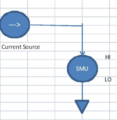
I try cascading two pxi 4130 (EMS of power) by the need to at least 28 volts forsomething else. After these two pxis wiring, I found a problem: using labview, as indicated in the image below, after having generated 14 V for the first and 14V to the second, I'm obtainning 21V on my external mutimeter (instead of 28) AND indicator, is also 28 BUT using the NI DCPower Soft front panel, I got 28V so could you help me find where this loss comes from? Why have I not 21 instead of 28 on my multimeter?
Thank you
You know. A snippet of code would help really a lot more than the attached pngs. Just edit select all (Ctrl + A) and Edtit > Create extract selection
You always set after setting the level of the beach, but this isn't your problem.
You see 22V on your meter because SMU outputs are not in series (not Wired) if they have BEEN in the series the currents would be identical. Of Kirchoff laws cannot be violated.
Tags: NI Software
Similar Questions
-
I use a 4130 PXI SMU to test a 3V battery transmitter RF. The unit goes through a sequence that requires up to 20mA current then goes into standby mode that should attract current in the low range AU in operation. The problem I have is downranging the 4130 available lowest range. The idea is to turn on the unit with the SMU put on the beach of 200mA. After the passage of the device through his power over the cycle, I need to change the range up to 200mA range and measure the off current. It seems that the EMS is change only from the beach on the initial installation. Attached is a snip from my code, any help is greatly appreciated.
Hi Phil,
I have rebuilt your code and was able to recreate the error you experienced. I think I have an answer for you.
You need to replace the VI niDCPower initialize with the niDCPower initialize VI channels. The difference is that the VI initialize the session with the SMUS in the State, is not the case to initialize it with Options of VI. For this reason, you should also place a niDCPower VI launch before your niDCPower configure output Enabled VI. Programming of a NOR-DCPower session States are described in the link below:
Programming States - OR DC power supply and SMU 1.4 Help
http://zone.NI.com/reference/en-XX/help/370736F-01/ni_dc_power_supplies_help/programmingstates/I have also included links to pass on the details of the various functions involved in the code:
niDCPower initialize VI - OR DC Power Supplies and SMUs 1.4 channels help
http://zone.NI.com/reference/en-XX/help/370736F-01/nidcpowerviref/nidcpower_initialize_with_channels...niDCPower initialize VI - OR DC Power Supplies and SMUs 1.4 help
http://zone.NI.com/reference/en-XX/help/370736F-01/nidcpowerviref/nidcpower_initialize/niDCPower run VI - NI DC Power Supplies and SMUs 1.4 help
http://zone.NI.com/reference/en-XX/help/370736F-01/nidcpowerviref/nidcpower_initiate/After making the changes I described above, I was able to run the code without generating an error.
-
I3 4130 map graphics and Power supply
Hey guys, I have an i3 4130 with 8 GB of ram,
http://support.HP.com/us-en/document/c04119419
Of course, this processor and ram are good for the game, as I have seen online videos of people playing bf4 and crysis 3. I also want to play these games and cs: GB and dirty bomb and dragon age. I don't really like playing high heat, the middle is fine for me. I really want to get a r9 x 270 BC, they are in a large part to the best buy right now. I will also buy a 650W power supply to go with it. My boyfriend is a geek and can install it for me. I took action, and I can fit such a graphics card or the gtx 660, in my case. [cards that are 10 x 4]
However, I saw in another post that my motherboard has a connector 4-pin. Is this bad? The website says that my motherboard can support up to an i7 uprade!... So why not other new powerful pieces such as a GPU or a power supply. I get that HP does not have computers for games. Why would they do a motherboard that can run an i7, but not an equally powerful GPU. I get that HP does not have the gaming PC, but those of office. However, it is the PC in my family study, so I'll try to make it work.
Another way is for ma to get the GTX 750, because this card has a minimum required 300w power supply.
http://www.Newegg.com/product/product.aspx?item=N82E16814487024
However, a person in another forum said that HP uses cheap power supplies and will not have enough tension on the 12v rail. is this true? If this way works, I definitely don't go this way as it is easy... also no need external with this map of power cord. However, if my power supply does not have enough Volts on the 12v rail, so I'll just take the graphics card I want and needed food.
It's really frustrating me because I played some very old games [rtcw, and] with friends on teamspeak at night and my integrated graphics card could handle, but now they are turning on modern games that I can't play and I reallly want to understand this before you go and spend a lot of money. Thanks for any response.
Andrew, welcome to the forum.
andrewmorgan98 wrote:
Hey guys, I have an i3 4130 with 8 GB of ram,
http://support.HP.com/us-en/document/c04119419
Of course, this processor and ram are good for the game, as I have seen online videos of people playing bf4 and crysis 3. I also want to play these games and cs: GB and dirty bomb and dragon age. I don't really like playing high heat, the middle is fine for me. I really want to get a r9 x 270 BC, they are in a large part to the best buy right now. I will also buy a 650W power supply to go with it. My boyfriend is a geek and can install it for me. I took action, and I can fit such a graphics card or the gtx 660, in my case. [cards that are 10 x 4]
However, I saw in another post that my motherboard has a connector 4-pin. Is this bad? The website says that my motherboard can support up to an i7 uprade!... So why not other new powerful pieces such as a GPU or a power supply. I get that HP does not have computers for games. Why would they do a motherboard that can run an i7, but not an equally powerful GPU. I get that HP does not have the gaming PC, but those of office. However, it is the PC in my family study, so I'll try to make it work.
Another way is for ma to get the GTX 750, because this card has a minimum required 300w power supply.
http://www.Newegg.com/product/product.aspx?item=N82E16814487024
A: I definitely recommend that you try the EVGA GTX 750 Ti. I read a lot of good things about it. It does not all the connectors extra power on the power supply. Regarding the PSU in HP computers is lousy, the fact is that they install the power supply that is compatible with the OEM components. Even if their computer can be upgraded, they design that enable out of the box. You can try with the current 300W PSU, but if it does not work, I suggest you buy a power supply at least 500W; 600W would be even better for futute upgrades.
However, a person in another forum said that HP uses cheap power supplies and will not have enough tension on the 12v rail. is this true? If this way works, I definitely don't go this way as it is easy... also no need external with this map of power cord. However, if my power supply does not have enough Volts on the 12v rail, so I'll just take the graphics card I want and needed food.
It's really frustrating me because I played some very old games [rtcw, and] with friends on teamspeak at night and my integrated graphics card could handle, but now they are turning on modern games that I can't play and I reallly want to understand this before you go and spend a lot of money. Thanks for any response.
You can see my answers to your questions above in orange. As suggested, the GTX 750 it should work for all the games you mentioned.
Please click on the Thumbs up button '+' if I helped you and click on "Accept as Solution" If your problem is resolved.
-
Can you have SMU 1062 q turn on without using the power button
I use a q SMU-1062 for a test project that will take place inside a protective case. The power button on the chassis will be covered by a plate on the protective case that make it boring and difficult to switch on using the power button on the chassis. The chassis will be plugged into a power strip of travel - lite which is mounted in the case. Is it possible that I can have the power to frame on when I turn on the power strip?
I found another route. In the controller BIOS, I changed the parameters of loss of AC power to TURN on after that AC is returned. This allows me to use the power strip in my configuration to control the electric network distributed to the controller. The following steps will describe how I got this.
- Power of the SMU-8115 controller.
- A message will appear on your screen, press
to enter SETUP - Select 'Remove' (quickly, because you don't have a lot of time before the window disappears and the controller continues to load normally.)
- This will open the main Menu of the BIOS
- Select the Advanced tab (use the arrow keys to highlight the selections and the different tabs, select a setting change with 'enter'
- Select > Configuration power and rest
- Change the configuration to power on when power is restored.
The controller can be normally close by using the start menu, and "shut down".
Start button / stop of the chassis is still capable of turning the power on to the controller, but now when I shut off the AC power strip and then return power, get the controller chassis.
-
Hello
I have SMU - 1065 and it is a part of a large system the system controlled by a switch.
I want the PXI Init (online) when I press the main power...
I'm guessing there is a switch or a jumper inside the PXI, a know where or you can give me a link to a manual...?
Hi Kobi Kalif,
If I understand you correctly, you want to on your frame when your line is under tension of your chassis? If you want to replace the power switch on your chassis, you can set the switch to disable on the back of your chassis to "manual". This will allow your chassis to power on automatically as soon as the line is energized. To learn more about this option and other options, see the Article knowledge base I linked below.
Characteristics and the NI SMU-1065 user manual
G Brandon
-
SMU-5606 Enable noise Source Power
Hello! I'm writing a measure of noise figure using the ASB SMU-5668R, which has an SMU-5606 inside. There is a noise 28V output Source I can use to connect to a source of noise. I looked through the drivers NOR-DAMA and succeeded in finding a property node (niRFSA-> Device Specific-> 5606-> noise activated energy Source) where I can wire an enumerated type constant (enabled/disabled) to fight against it.
If I connect a DMM to 28V output and toggle this property node, I see not 28V light. Are there more code that must be used to correctly set up the source of noise the 5606 28V output? I enclose a VI test I use to solve problems.
Thank you!
Hello
You must add a call to niRFSA Commit.vi following toggle to validate the parameter (which is cached) hardware.
I hope this helps!
Kind regards
Andy Hinde, MBA
Senior systems engineer
RF and communications
National Instruments
-
Type of step IVI supports NI-SMU-4112?
Hello, guys
I have a SMU-4112 and four of the PXI-4130. When I try to configure my SMU-4112 with PowerSupply IVI step Type, an error occurred.
-------------------------------
An error occurred the call "RunStep" in "ISubstep" of "ZNIUGOL of Types of step TestStand Ivi"
An error occurred during the execution of the step.
Component works IVI control error: IVI configure failed for logical name ' 4112 ".
Details: Attribute or property not supported. Attribute: NIDCPOWER_ATTR_OVP_ENABLED, Channel: 0 [IVI. Error Code: BFFA0012]
Source: TSIviStepTypes--------------------------------
Surely, I disabled the checkbox "OVP on" editing it IVI Power Supply stage dialogue. My system configuration is,
IVI Compliance Package 4.6
NOR-DCPower 1.8.6
SP1 OR TestStand 2012
My PXI - 4130 s work well with the type of step of IVI. Type of step IVI supports NI-SMU-4112? Or I do something wrong about this?
Kind regards
Joonam
Hi Joonam,
PowerSupply IVI step does not currently work with the 4112.
The 4112 can't stand the ÖVP. If the NIDCPOWER_ATTR_OVP_ENABLED attribute is set to True, the error you described is expected. If it is set to False, no error should be generated. However, an error is generated when it is set to false. This is incorrect behavior in the pilot and has already been documented under the Corrective Action report (CAR) #437105. This question will probably be corrected in a future version of NOR-DCPower.
Step PowerSupply IVI is hardcoded in the attribute set to true or false, depending on the value of the checkbox in the tab limits. Workaround for this problem is to replace your PowerSupply IVI step with a step based on a code module that does not seek to set the OVP_ENABLED attribute at all.
I apologize for any inconvenience that this is for you. Let me know if you want more details.
-
4130 PXI channel 1 red led output
Hi, I need help with my SMU - PXI-4130 - the red on the channel 1 output is allaways, during my measuremnet.
Is that even correct or means this 'ERROR' mean?
And where can I find information, I was looking on ni.com has not found the right pdf.
Hope someone can help me with this one - Thnx a lot.
It is red or orange? Using the link to the NI DC Power Supplies and SMUs help who gave JeremyDC and navigating devices > NI PXI-4130 > front, you can see that Amber would indicate that you operate at the current limit, or 'compliance' (help file > Fundamentals > compliance). It simply means that you hit the maximum allowed current (current limit) before reaching the required voltage output. It is not an error, but a built-in feature of SMEs.
You may need to just allow a current higher limit if you want to get to the requested voltage output, or you can increase the resistance of the ESA in order to limit the amount of current happening as a result of the applied voltage.
I hope that helps!
-
Power Mac G5 power problems...
Hello, on a quest to find a G5 computer, I found an early 2005 Power Mac G5 (2x2.7GHz). The first time I plugged it in and turned on, it works beautifully. The second time, I pressed the power button and heard a loud noise from the power supply. I replaced and this is what is happening now:
When I plug the power cable in, there is a small clicking noise about a second after plugging in, and the power led on the front of the machine flashes for the click. However, it does not at all depend on when I press the power button. When I unplug the cable, it makes the same noise about a second after I unplug the unit. I see a pale glow of the light output after unplugging it.
Anyone have any suggestions to solve this problem? It is part of a collection, that's why I want to do operational.
There may be defective capacitors or other power supply problems, including
overheating in the dust inside the power supply or air channels. And
If the device is cooled by liquid, other things may be involved.
Since all the PowerMac G5 power supplies are considered to be custom,.
to get a good replacement is a way hoped to improve the situation.
Unlikely as is, actually an inexpensive job.
Have you tried a SMC power management unit reset? Or reset PRAM?
To reset NVRAM (PRAM) see:
• How to reset the NVRAM on your Mac - Apple Support
Several links appear in the result of this research; some look promising:
https://DuckDuckGo.com/?q=Troubleshooting + G5 + PowerMac + power + supplies& t = ffsb & AI = web
I read about the noise, the PowerMac G5 can do when some power components
fails; Troubleshooting is involved. Somewhere I had a link to a source for official PDF
REPAIR, download for offline use. -I do not see if I can locate the item...Apple Power Mac G5 (early 2005) manual .pdf
Apple Power Mac G5 (late 2005) manual .pdf
Apple Power Mac manual G5.pdf
Good luck!
-
generation of sinusoidal wave with smu
Is it possible to generate, for example, one 3 a 50 Hz sine wave with SMU 4138 or 4139?
THX
The DCPower API provides no screws to use blocks of power or SME like FGENs. However, it is possible to program the jury at the exit of the standard functions by translating the desired frequency and amplitude to a sequence of continuous output with delays of source is defined so that the output function the user selects is output on the terminals of the device.
The attached program allows you to use a NI 414 x, NI 4135/4136/4137/4138/4139 as a FGEN. As it is, the program is limited to a maximum output frequency of 5 kHz.
I have attached a version of the code for the current output and a version for output voltage waveforms.
-
Hello
I'll try to find measures PTA of the OFDM signal with 3 MHz of bandwidth using block ACP in the kit to SMT tools. But I'm out like NaN. Why is it so? Can someone tell me please?
And I use NI SMU-5645R Transceiver.
Thanks in advance!
Looks like you can get the ACP SMT block NaN whenever steps out towards negative infinity. The way that the acquisition has been set up, I think that you receive an error on the fetch call, which returns an empty array of waveform, which adopted the ACP bloc. Which can lead to a negative infinite result. I have attached a modified project that works on my VST.
Here's what I changed. First of all, I don't have a map of timing and synchronization, so I had to use scripts and a marker event to synchronize the generator and Analyzer. You can replace that with your overall software trigger code. Second, I made the acquisition changes I mentioned above: finite number of samples, endless documents, connected to the PXI trigger trigger 0 reference.
Finally (and I don't know if this is necessary), I replaced your QI to spectrum VI with the SMT. the Spectra parameters are then passed to the ACP VI VI range.
To do my VI properly, you will need to fit you your waveform. I used the script mode to synchronize the generator and parser which means that I had to use mode instead of the mode of power peak power average. Once you add your rear synchronization code, you can switch to the mode of the ARB and average power mode.
-
External sample clock change takes a lot of time on the SMU-5186
Hello
I use the external Lv - niScope EX Clocking.vi example to define SMU-5186 using an external sample clock. However, it takes a long time, 5-6 minutes, before I can get the first block of data acquisition.
Then I run the example 'niScope EX Acquisition.vi Configured' to switch to dashboard clock. There are also 5 to 6 minutes on the first acquisition.
I think maybe the SMU-5186 made some calibration when I change the source of the clock.
Anyway is to ignore the calibration? Or make it faster?
Thank you very much
Yiming
Yiming,
Delays in acquisition are caused by calibration routines that must be performed on the engine to sample (ADC) every time that changes sampling rate. This ensures our justified precision specifications.
I don't know if you've noticed also calibration of Power-Up, which will take 5-10 minutes to complete when the unit is turned on. This is mentioned in our specifications at page 18:
http://www.NI.com/PDF/manuals/373257b.PDF#page=18
I hope this helps.
Nathan
-
Is it possible to read the voltage/current SMU after the closure of the original session?
What is the method, or is it still possible reading the voltage and current of an SMU SMU-4138 measurements after the original configuration session has been closed? I have a (relatively) long Teststand sequence that sets up the EMS to provide power to the ESA, then conducts tests and along the way I have to take the readings of SMU. I was always under the impression, it is advisable to open and close the EMS quickly set up, but the 3-State programming model does not allow a way to jump into the running state of Init with channels VI, except through committed and engaged States and thus any stop in the process. The power measurement VI only works if you are in the Running State. Seems like a no-brainer, so what Miss me?
bholsinger wrote:
I was always under the impression, that it is recommended to open and close the EMS quickly set up
It's BAD advice. You open at the beginning of your program, you do whatever it takes with it inside your test (configure, read, etc.) program and you don't log off not until you stop your program.
-
SMU, used for the measurement of current
Hello
I need to measure current in the range 5 to exit 10uA by a current source PIN. I would have usually connected PXI4065 on this PIN and measured current. But in this case the current to be measured is low.
I have EMS 4130, which has high accuracy of current measurement to 200mA range (0.03%+0.02)uA.
Can I use the current part of the EMS (CH1) measurement to measure current? What should I activate CV outputs (Hi = 0V) who appears in the soft front panel?
Or just without activating the outputs I can measure the current sink. The program of flexible panel displays current measurements, but I don't know if the EMS can be used like that.
Thank you
Not sure NI SMEs, as I have not had the chance to use it yet. SMU of Agilent could be used this way, so I guess with OR as well. You must use out SMU in constant voltage source / I measure mode. Would you say the SMU to hold the voltage at 0V, and allow current to the sink (or source) as necessary to maintain this 0V output.
-
Measurement time 4132 SMU is too high
Hello
I use PXI - 4132 DC EMS to perform some DC measurements at high speed. I just took a 1 K Ohms resistance, forced 1mA and measure 1V. I have this done configuration and code completed. I get the correct measurements. But my problem is with the measurement time. The total duration is about 45ms to complete installation and measurement, with the exception of the 'initialize and close '.
I checked the time at every step and I noticed that the maximum duration is taken during the "voltage reading. Out of the total 45ms, it takes about 34ms just for a measure. It's just a VI "Ukraine power measure" takes about 34ms, which is ridiculous compared to the Kiethleys. I tried to vary the time of "openness" and turn off the 'Auto Zero'. But the measurement time is still high. Can someone help me and let me know what is the best time of the measurement obtained with 413 x series SME?
Thank you!
Hey Phx_tech,
The amount you reduce your delay source depends very much your HAD and how regular you have to your level of tension until you start taking your measurements. If your Instrument is reactive, you can see discount gas and unintentional ringing during the transition from your output level and therefore would allow enough break-in before taking your measurement. The best thing to do is to experiment with different delays of source and see how much delay need you to get a consistent and reproducible measure. If you have a scope that is available, it will also show you the step response of the SMU with your Instrument. If your first reading is higher than your other readings, that this could very well be a problem with not enough time settling. What kind of DUT Testez_ you?
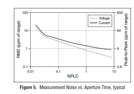
From page 4 of the specification, you can see that 1 PLC, we can expect about 1 ppm RMS noise of the range to 1 PLC. This means in the range 10 au our measurement noise would be 10 pA RMS or 60 pA pk - pk. However, your DUT + cables will pick up the extra noise and you should consider using wires of twisted shield pair to reduce noise picked up in your system. The shield can be terminated at the mass of the chassis on the side EMS of the cable to help reduce noise appearing in your measurement.
Let us know what you find after experimenting with you HAD.
Thank you!
Brandon G
Maybe you are looking for
-
HP Envy 5534: Need help to find the 32-bit drivers - Win7 - basis for HP Envy 5534
Please see above, I'm unable to locate the drivers necessary 32 bit for my HP Envy 5534. I need to use the base without the supplied software drivers and I have a 32-bit system. A permit would be appreciated Thank you.
-
How do we uninstall vista security 2011
I would like to know if I can uninstall vista security 2011 and if yes how to do that.thank you
-
Get OTA it downloading applications to work
Hi all I created an application with BlackBerry plugin for Eclipse. Both cod files (COD several files compressed into one) and the jad file was created. However, once I have sign cod with my developer key signature files, the size of the cod files
-
Sync blackBerry Smartphone Music Sync and media on "BOLD"
Hi all When I go to Blackberry.com on my "BOLD" there is a link that says "sync your music iTunes office with your blackberry smartphone: find out how. When I get the link to download on my PC for the media sync... It does not seem to do anything. An
-
Hi, how long does get a pass?