cDAQ-9172 chassis ground
cDAQ9172 said that the Earth correctly (page 15, Fig. 6) user guide the chassis:
"attached a leg of the ring to gauge AWG 14 wire. Connect the leg of the ring to the Terminal on the side of the cahssis screws from land. Connect the other end of the cable to the Earth of the system security.
So I connected the leg of the ring to the ground on the side of 9172 screw. Can someone show me where should I attached the other end of this cable to found the chassis correctly?
Thank you very much!
If you use a cable with shielding, also of the shield of protection must be linked to the earth so that it is truly effective. Connect the shield at the end of the cDAQ should suffice. Please note that the shield of the cable is different from the + and - connections in a cable. If you use a 9234 BNC connectors, it is likely that you have not also shield you must connect. Most of the time, shield wire is twisted cables.
Tags: NI Hardware
Similar Questions
-
Bad analog output help Every_N_Samples-NI-9263 cDAQ-9172 chassis (works with cDAQ-9178 chassis)
Hello
The NOR-9263 analog output voltage geberation works correctly with the cDAQ-9178 chassis but gives wrong result using the chassis NOR cDAQ-9172.
In the attached code example, a single cycle of a sine wave is composed of 40000 samples and came out in the background using Every_N_Samples at a rate of production of 5000 samples per second.
The output buffer size is set to 10000 samples.
Prepare us the buffer writing 10000 samples 1, then write the remaining data in the background using the Every_N_Samples callback.
Bug: Using the cDAQ-9172 chassis, to the 5000 s/s sampling rate with the help of an external field (or through closure to another HAVE), we observed that 1 10000 samples came out twice, followed by the rest of the waveform. The last 10000 samples are never exits. If you are working properly, we would expect to see 1 full cycle of a sine wave.The bug does not occur with the chassis NOR cDAQ-9178. I use the driver NIDAQmx v9.2.1f0 on Windows XP
The bug does not happen with simulation devices, so you will need to use harwdare real to reproduce.Please find attached an example of code C based on the example program OR "ContGen - IntClk.c" to reproduce this bug.
Thank you
whemdan,
The MathWorks
Hi whemdan,
By default, DAQmx regenerate old samples if no new data is available. To give the correct behavior, you can:
Use DAQmxSetWriteRegenMode to disable the regeneration (DAQmx_Val_DoNotAllowRegen). In most cases, this is recommended if new data are written continuously in the buffer as the build is in progress.
If you just need to generate 40 k samples, you can write them just all at once, rather than in 10 pieces of k (the code you attached probably is just an example, so I'll assume that you have a reason to write the data into segments in your actual code).
I think the difference in behavior between 9172 and 9178 can if explained by the different way, buffering is set up on each product. The 9172 uses a buffer of 8 k (on the STC2) in all cases (source). The 9178 uses an 8 k of memory buffer (on the STC3) If you use regeneration shipped, but uses the 127 samples FIFO cartridge, if you use no on-board regeneration (source).
Then... on the 9172 8191 samples are immediately transferred to the FIFO. By default, the hardware is going to request new data when the FIFO is less to fill (this is configurable with DAQmxSetAODataXferReqCond). I'm not sure what the transfer data request size is in your case (you can set the maximum value with DAQmxSetAOUsbXferReqSize), but obviously it is bigger than the other 1809 samples that you have not yet sent to the Board of Directors of your first entry. At this point, the pilot will regenerate 10 existing k samples so that sufficient data will be available to meet the demand of data transfer.
The 9178 however use the FIFO of 127 smaller samples so you will not have the same behavior in your case.
In summary, the behavior is explainable by the difference of material. If you want to avoid to regenerate old samples, you should ban the regeneration using DAQmxSetWriteRegenMode.
Best regards
-
new cDAQ-9178 chassis was smaller than the cDAQ-9172 old buffer?
Digital waveform features:
Waveform acquisition (DI) FIFO for cDAQ-9172: 2047 samples
Waveform acquisition (DI) FIFO for cDAQ-9178: 127 samples per slot
This means that the new HW (9178) has a much smaller than the old buffer (9172)!
I want to run a correlation over generation/acquisition at 2 MHz with 2000 samples. Does this mean that the new chassis will not be able to acquire the whole of the data (I use a NI 9401 module inside the chassis)?
FIFO sizes are misleading and not a true indicator of the chassis supporting the streaming is not the single buffer. We did some tests comparing the latest and cDAQ-9172 chassis. You will not notice the difference, especially with your application to a finished task of 2 000 samples at 2 MHz. With 2 000 samples, you can run your DI task on your chassis cDAQ-9178 at 10 MHz if you wanted without problem (don't try with continuous or even finished tasks).
The only time where the FIFO size really comes into play is when you run a primary task at high rates, say > 5 MHz, even if it is system dependent. At these speeds a FIFO that is deeper 2 000 samples you buy only tens or hundreds of additional microseconds when Windows jitter is measured in milliseconds.
I would be very surprised if there is a practical application that worked on a cDAQ-9172 chassis which did not work on newer USB cDAQ chassis.
-
How to use an internal counter of the cDAQ-9172 for measure PWM and generate the frequency?
Hello
Requirement of my project is to measure 6-channel PWM and generate 5 frequency channels.
Suggestion of engineer OR bought cDAQ-9172 chassis and NI 9423 (8 DI correlated) and NI 9474 (8 correlated DO) for this requirement. I have a few questions
Article:
1 > what should I know to customize my CompactDaq 9172 chassis
http://zone.NI.com/DevZone/CDA/tut/p/ID/9367
I know that this way to synchronize the physical support 32 correlation system pin o for housing 1-4.
=> I'm not really sure how to use these channels synchronization support.
2 > using internal counters on one NOR cDAQ-9172 as a sample for other tasks clock
http://digital.NI.com/public.nsf/allkb/ADFC4DD8C9690232862575B70079FBD4
I know that I can change the ownership of the physical channel so I can get 2 meter outside the frame 6 and 7.
=> I do not think that this solution will be me because I can use only 2 counters with this method.
Could someone tell me please how to fix my project requirement? How to choose the setting for DAQmx screws?
I have experience with measure the PWM and generate the frequency, but with separated against only.
Best regards
Thang Nguyen
Hey Thang.
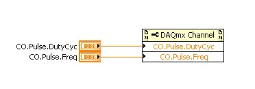
AHA... for this, you can use the channel property node.
See you soon
Lab
-
Impossible to get more than 1 channel to read with DAQmx cDAQ-9172 under Windows 7
I have the cell load, voltage, and input thermocouple connected to a cDAQ-9172. My sensors entries have been scaled and verified in MAX, and all of them work. DASYLab 13, the driver is "dcDASY.dll" and the hardware configuration is "NI MAX.
When I add a task NEITHER-DAQmx Analog Input (that is, a set of scales) it appears correctly. If I add a second channel of the task and select it, I get this message:
'Channel of task name saved with the module is not available. DASYLab resets the module parameters for usable first channel name task. »
The name of the task remains the same for each new channel I have Add. If I change the name of the task by using the tab to the drop down menu, it says:
"You have configured several ways out for the module. If you modify the task, you lose the settings. You want to change the task? »
Both display the same data channels, and I can't work simultaneously several channels. It seems I missed something obvious, but I can't.The parameters are:
Measurement and Automation Explorer 4.6.1
NOR-DAQmx 9.0Material:-cDAQ-9172
Slot 1 - NOR 9215 (0-10 Vdc analog voltage)
Slot 2 - NEITHER 9211 (thermocouple)
slot 3 - NI 9481 (relay)
slot 4 - NI 9237 (entry deck w / excitement)
housing 5 - OR 9402 (DIO)
slot 6 - NI 9263 (0-10 Vdc output analog)Thank you
You can't perform different tasks (continuous) HERE on a single chassis. The first tasks that starts will be 'the resource booking '.
Combine the AIs of the various modules in a single task (see photo): start by creating the task of thermocouple. Then add AIs 9237 (e.g. Kraft) and 9215 (volts) using the button with the blue, symbol. Set the mode of synchronization of the task of "continue". Save the task, start DASYLab (second photo).
Change a task (adding channels, etc.) to the MAX while DASYLab works always, will result in unexpected behavior. To synchronize the configuration of MAX with DASYLab, you will need to close/restart DASYLab or use the 'sync' of the function (see photo 3 "syncmax.jpg"). You can set this function as a shortcut by right-clicking on one of the eight green or grey circle things.
You should think about an update of the MAX/DAqmx drivers. 9.x is a little outdated.
Updated at least DAQmx 9.9, better 14.x or 15. 0 (stay far 15 1.x).
-
Sampling frequency for digital sampling (cDAQ-9172 & NI 9401)
Hello!
I have a cDAQ-9172 with NI 9401 C-series (digital) module. I would like to taste the digital inputs with a sampling frequency of e.g. 400 or 200 kHz. My problem is that I can only choose a clock 100kHzTimebase and therefore only get a sampling rate of 100 kHz. The 20MHzTimebase clock is too fast, as it gives me a sampling rate of 20 MHz). Is it possible to get a defined user e.g. 200 kHz sampling frequency, dividing for example down the clock of 20MHzTimebase?
Thank you! Last post and this article using the internal one or cDAQ chassis counters has solved my problem.
-
The following vi allows the user to choose 1-8 global data channels and record is a record for a certain time or number of samples. A file is written to the location selected users. Any channel can be separately filtered through an IIR filter, and the user can select the rate and sample size. There is a graphical display of each channel and a digital display for each. The problem is that I get a time-out of samples. If I put the high sample rate (say 2500) I start missing samples. I use 9172 cDAQ chassis. The error is 200279, tried to read samples is no longer available. In the recording of samples or when you save a timed record, the number of samples are not correct at higher rates. Can I have a problem with my logic of vi?
The time base of 80 MHz can be used for the counter / timer source contributions. Generally, the 20 MHz or 100 kHz is used to generate the synchronization signals HAVE and AO. This information and more, are in NEITHER cDAQ-9172 User Guide and Specifications. Therefore, the question with the x-axis is probably because he is trying to use a basis of time which is too high. In order to read faster, we can increase the number of samples per channel to read with the lu DAQmx vi, as suggested by this article in the knowledge base . In addition, you may want to move the part of the acquisition of data from your application to a producer / architecture of consumer, who may also increase the rate of reading. There is an example of the producer / consumer at the bottom of the knowledge base article linked above architecture. In addition, this Tutorial DeveloperZone has a good explanation of the design model.
David
Technical sales engineer
National Instruments
-
How many quadrature encoders may be read together with the cDAQ-9188 chassis?
We will record position periodically 8 engines (at the same time as we are to the corresponding samples entered analog). It seems that the 4 built-in counters limited chassis to 4 encoders. Is this correct? I am familiar with modules of counter PLC which manage high-speed counting, and then the CPU posts periodically to update the total values. This is how the NI 9401 card would work?
Hi jtrout,
You are right the 4 built-in counters than the cDAQ-9188 chassis 4 encoders. The following article deals with the use of the NI 9401 card for encoder measures: http://www.ni.com/tutorial/7109/en/.
-
Generate a pulse train, NI 9402 modules in cDAQ-9174 chassis
I have two modules NI 9402 in a cDAQ-9174 chassis.
When I output a pulse train on a specific line of the PFI to a specific module, the pulse train is out on the right line of PFI, but on BOTH modules.
I want that the pulse train out only one of the modules.
for example, I select cDAQ2Mod1/ctr1 to output a pulse train on PFI3 of module one. I hear the pulse module one PFI3 train, but I also get it on PFI3 of module 2.
I am also a measurement of separation of two edges with a different counter, but I don't seem to have this problem. (The measure only works when I have the signals connected to the module that I've specified.)
-Paul
This is the Vi I work with.

Hmmm... Looks like it's actually only after I exit a signal on that line. Maybe I should try to clear the line.
-Paul
-
cDAQ-9172 error message 200485 in Labview and 88705 Max
My company has had this machine for awhile not operational. I decided it was time to get this thing running but continue to flock to the top with a 200485 error when I try to run Labview and 88705-error when I try to change anything in the cDAQ-9172 runs at MAX. I'll try to update the software and reinstall the drivers in the hope that it is a mistake to simple communication from the device to the computer, but in case it's something more serious that I am not seeing that I wanted to post this in the hope that someone might have an answer. Thank you
I would start by checking the device loader OR. Error 88705 in MAX is caused because the Windows Service OR device charger has not been loaded. Below is an article about starting the service knowledge base.
http://digital.NI.com/public.nsf/webPreview/89A6279147AA994A862572DF00491BCA?OpenDocument
Thank you
Steven Koo
-
Run an application of LabVIEW 8.6 in win 7 (using the cDAQ-9172, 9219, 9422)
Hello.
I did a LabVIEW application for a few years. At that time, I used windows XP and labview 8.6. The material used is the cDAQ-9172, with NEITHER-9219 (reading of four strain gage sensors) and a NOR-9422 (using only a single input frequency).
First of all, can I install my old version of labview 8.6 in my 64-bit computer to windows 7? I got an error message when I tried...
Second, how much should I install? My old computer was slower after you install labview with its pilots. Perhaps I installed too much? Do I have to install 1, 5 GB DAQmx drivers?
If I need a new version of labview for win 7, how much is an update?
Thank you!
Hello
First version of LabVIEW which is supported on Windows 7 is LabVIEW 2009 SP1.
Regarding the drivers, if you want to develop or run VI:s in LabVIEW with the DAQmx API, then you must install the full DAQmx driver.
If you only meet built executable in the LabVIEW environment to run, then you just DAQmx Base Runtime.
If you also want to be able to configure the data acquisition equipment (to the MAX) in a runtime environment, you should also Configuration DAQmx execution.
For upgrades of licenses if please contact the local office of National Instruments or follow this link:
http://ohm.NI.com/advisors/UA/pages/UA/intro.XHTML
Best regards
Klas Andersson
OR Sweden
-
Encoder speed and orientation on the NI 9401 in cDAQ-9172
Hello, I have a module or 9401 for my cDAQ-9172 and she is now installed in five slot to connect a dual channel encoder. Channel A is connected to pin 14 and channel B to pin 17 and the encoder is powered by 5v dc.
I want to measure the speed and if possible rotation orientation.
Fix for this that I started the VI, who can count total impulses in the encoder.
My question is, how do I change the DAQmx create frequency channel and DAQmx Read of impulse 1 Chan 1 Samp Freq counter, calculate the speed real encoder and orientation?
Quintino Hi and sorry for not having answered quickly.
Your VI works perfectly well for low frequencies with me. If you want to measure fairly high frequency (> 1 kHz), you may need to check how a measure of 2 meters. You will find an example attached (lv2009). Just plug the signal at the source of one of the meter (ctr0 for example), then set it to the value of the counter on the VI ctr0 control. Use a splitter too high (4 is fine). I was able to compete with the signals of 1 MHz on my Board.
If the problem of failover is still happening after that, try to make a measurement with a low frequency generator and 1 meter to check if the problem is the system (it takes).
-
Hello
I am using a cdaq-9172 with a NI 9421 pass. I want to watch the first 4 bits as an integer and see in the shared variable engine. Any thoghts on how I could do this? I have tried to make a new global virtual channel but can select entry or entries of port. Entrance to the port is a bool value and not integer.
Problem solved... Do not put everything inside the while loop.
Thanks for your help!
Kevin
-
I overload with cDAQ-9172 and the NI 9234
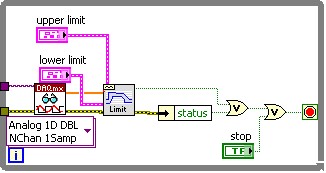
The DAQmx Read property for ' overloaded channels exist "is not supported by my hardware (cDAQ-9172 with NI 9234). What can I use to stop the vi if the tension in the analog input is overloaded?
-
Synchronized in my cDAQ-9172 multiple input signals?
I use NEITHER cDAQ-9172, and I currently have 20 signals from various sensors (acceleration, speed, power, etc.). How can ensure me that when I start my vi, all input data is saved from the exact same hour?
Here is a link that I hope is useful, do not hesitate to ask questions:
http://zone.NI.com/DevZone/CDA/EPD/p/ID/5259
This program example will show you how to perform a synchronization module multiple analog inputs with CompactDAQ.
Maybe you are looking for
-
On Satellite Pro A10 HARD drive replacement
Hi all Ive currently got my moms Satellite Pro A10 sitting in front of me. Wouldn't load XP at all so I downloaded Knoppix and ran the liveCD on the laptop. After some tests, it seems that the HARD drive has failed. The vehicle currently has a 30GB H
-
Satellite A135-S2356 won't boot after BIOS update
I have Toshiba A135-S2356 and am having the same problem.Mine started to do after I was I had problems with only 2 of my usb ports work. I saw a topic on it and there was a link to update the system bios, http://laptopforums.toshiba.com/t5/General-Te
-
can I use easy transfer from xp 32-bit windows to 64-bit win7?
Windows easy transfer can I use windows easy transfer and transfer my computer running windows 7 / 64-bit on my computer that is running windows xp service pack 3 32 bits of the operating system even just to store my other (win 7) my other (win xp) s
-
Change the Lollipop bluetooth visibility
Lollipop Xperia Z2, after update section is more available Bluetooth device name. That's why you can't make your phone visible to others. Thank you
-
Avoid the popup on click ButtonField
Hey guys, rite, I've been looking for centuries now, and the problem I have is that I can't seem to stop the popup to appear, I looked through the forums and although there are a lot of things tell me how to do it, none of them seem to actually tell