Synchronized in my cDAQ-9172 multiple input signals?
I use NEITHER cDAQ-9172, and I currently have 20 signals from various sensors (acceleration, speed, power, etc.). How can ensure me that when I start my vi, all input data is saved from the exact same hour?
Here is a link that I hope is useful, do not hesitate to ask questions:
http://zone.NI.com/DevZone/CDA/EPD/p/ID/5259
This program example will show you how to perform a synchronization module multiple analog inputs with CompactDAQ.
Tags: NI Hardware
Similar Questions
-
Impossible to get more than 1 channel to read with DAQmx cDAQ-9172 under Windows 7
I have the cell load, voltage, and input thermocouple connected to a cDAQ-9172. My sensors entries have been scaled and verified in MAX, and all of them work. DASYLab 13, the driver is "dcDASY.dll" and the hardware configuration is "NI MAX.
When I add a task NEITHER-DAQmx Analog Input (that is, a set of scales) it appears correctly. If I add a second channel of the task and select it, I get this message:
'Channel of task name saved with the module is not available. DASYLab resets the module parameters for usable first channel name task. »
The name of the task remains the same for each new channel I have Add. If I change the name of the task by using the tab to the drop down menu, it says:
"You have configured several ways out for the module. If you modify the task, you lose the settings. You want to change the task? »
Both display the same data channels, and I can't work simultaneously several channels. It seems I missed something obvious, but I can't.The parameters are:
Measurement and Automation Explorer 4.6.1
NOR-DAQmx 9.0Material:-cDAQ-9172
Slot 1 - NOR 9215 (0-10 Vdc analog voltage)
Slot 2 - NEITHER 9211 (thermocouple)
slot 3 - NI 9481 (relay)
slot 4 - NI 9237 (entry deck w / excitement)
housing 5 - OR 9402 (DIO)
slot 6 - NI 9263 (0-10 Vdc output analog)Thank you
You can't perform different tasks (continuous) HERE on a single chassis. The first tasks that starts will be 'the resource booking '.
Combine the AIs of the various modules in a single task (see photo): start by creating the task of thermocouple. Then add AIs 9237 (e.g. Kraft) and 9215 (volts) using the button with the blue, symbol. Set the mode of synchronization of the task of "continue". Save the task, start DASYLab (second photo).
Change a task (adding channels, etc.) to the MAX while DASYLab works always, will result in unexpected behavior. To synchronize the configuration of MAX with DASYLab, you will need to close/restart DASYLab or use the 'sync' of the function (see photo 3 "syncmax.jpg"). You can set this function as a shortcut by right-clicking on one of the eight green or grey circle things.
You should think about an update of the MAX/DAqmx drivers. 9.x is a little outdated.
Updated at least DAQmx 9.9, better 14.x or 15. 0 (stay far 15 1.x).
-
Run an application of LabVIEW 8.6 in win 7 (using the cDAQ-9172, 9219, 9422)
Hello.
I did a LabVIEW application for a few years. At that time, I used windows XP and labview 8.6. The material used is the cDAQ-9172, with NEITHER-9219 (reading of four strain gage sensors) and a NOR-9422 (using only a single input frequency).
First of all, can I install my old version of labview 8.6 in my 64-bit computer to windows 7? I got an error message when I tried...
Second, how much should I install? My old computer was slower after you install labview with its pilots. Perhaps I installed too much? Do I have to install 1, 5 GB DAQmx drivers?
If I need a new version of labview for win 7, how much is an update?
Thank you!
Hello
First version of LabVIEW which is supported on Windows 7 is LabVIEW 2009 SP1.
Regarding the drivers, if you want to develop or run VI:s in LabVIEW with the DAQmx API, then you must install the full DAQmx driver.
If you only meet built executable in the LabVIEW environment to run, then you just DAQmx Base Runtime.
If you also want to be able to configure the data acquisition equipment (to the MAX) in a runtime environment, you should also Configuration DAQmx execution.
For upgrades of licenses if please contact the local office of National Instruments or follow this link:
http://ohm.NI.com/advisors/UA/pages/UA/intro.XHTML
Best regards
Klas Andersson
OR Sweden
-
Sampling frequency for digital sampling (cDAQ-9172 & NI 9401)
Hello!
I have a cDAQ-9172 with NI 9401 C-series (digital) module. I would like to taste the digital inputs with a sampling frequency of e.g. 400 or 200 kHz. My problem is that I can only choose a clock 100kHzTimebase and therefore only get a sampling rate of 100 kHz. The 20MHzTimebase clock is too fast, as it gives me a sampling rate of 20 MHz). Is it possible to get a defined user e.g. 200 kHz sampling frequency, dividing for example down the clock of 20MHzTimebase?
Thank you! Last post and this article using the internal one or cDAQ chassis counters has solved my problem.
-
No input signal (4-20 my expected) on NI 9208
Hello world.
I'm having trouble getting the analog input signal (4-20 my) using NI 9208 mounted on the cDAQ 9188.
Here is the configuration:
-pressure transmitter 2-wire connected (IN: + 24V) (OUT: pin NI 9208 AI6 code) (power from an external source sharing 0V and ground with pin NI 9208 COM)
- NI 9208: Vsup = + 24V (pin 19 & 37); COM = 0V is GND (PIN 9; 10; 28-29);. AI6 = issuer pin
[Clip, a drawing of the wiring]
-Pilot OR DAQmx 9.3
-10 Labview
-Windows 7
Using a DAQ assistant set up to acquire the analog current signal, the value I get on screen is fluctuating between 0.001 and 0.1 my.
I have inserted a device running on-line measurement between the transmitter OUTPUT pin and the pin of the 9208 AI6, here I actually get the signal 4-20 my.
As additional information, I measure 28V between Vsup and COM; 0.3V between AI6 and COM; and 27.7V between Vsup and AI6.
To make it as clear as possible I might add that first, every input channel has been connected to a transmitter, each giving the screen the value of my ~0.01 (ammeter not yet tested on each I-online the next step in my investigation, actually performed). Then I tried to identify the problem to connect to a single issuer (AI6). Result is always the same.
As the NI 9208 once functionned well a few months earlier, I think that the problem come from a transmitter that can have been wrongly. (I'm actually cheking all connections).
My question would be: is the 9208 comprises usually this device damaged (ADC?)? Or maybe it seems as if there is something I missunderstand?
No matter what piece of advice would be greatly welcomed.
Also, please forgive my English aproximous.
Thank you for your consideration.
Adrien QUEUCHE
Well, that was my mistake. I was reading my where I should have read A...
To any administrator: the subject may be deleted, I guess. Unless I deserve to be shameful for eternity...
Thank you.
Adrien QUEUCHE
-
The following vi allows the user to choose 1-8 global data channels and record is a record for a certain time or number of samples. A file is written to the location selected users. Any channel can be separately filtered through an IIR filter, and the user can select the rate and sample size. There is a graphical display of each channel and a digital display for each. The problem is that I get a time-out of samples. If I put the high sample rate (say 2500) I start missing samples. I use 9172 cDAQ chassis. The error is 200279, tried to read samples is no longer available. In the recording of samples or when you save a timed record, the number of samples are not correct at higher rates. Can I have a problem with my logic of vi?
The time base of 80 MHz can be used for the counter / timer source contributions. Generally, the 20 MHz or 100 kHz is used to generate the synchronization signals HAVE and AO. This information and more, are in NEITHER cDAQ-9172 User Guide and Specifications. Therefore, the question with the x-axis is probably because he is trying to use a basis of time which is too high. In order to read faster, we can increase the number of samples per channel to read with the lu DAQmx vi, as suggested by this article in the knowledge base . In addition, you may want to move the part of the acquisition of data from your application to a producer / architecture of consumer, who may also increase the rate of reading. There is an example of the producer / consumer at the bottom of the knowledge base article linked above architecture. In addition, this Tutorial DeveloperZone has a good explanation of the design model.
David
Technical sales engineer
National Instruments
-
Encoder speed and orientation on the NI 9401 in cDAQ-9172
Hello, I have a module or 9401 for my cDAQ-9172 and she is now installed in five slot to connect a dual channel encoder. Channel A is connected to pin 14 and channel B to pin 17 and the encoder is powered by 5v dc.
I want to measure the speed and if possible rotation orientation.
Fix for this that I started the VI, who can count total impulses in the encoder.
My question is, how do I change the DAQmx create frequency channel and DAQmx Read of impulse 1 Chan 1 Samp Freq counter, calculate the speed real encoder and orientation?
Quintino Hi and sorry for not having answered quickly.
Your VI works perfectly well for low frequencies with me. If you want to measure fairly high frequency (> 1 kHz), you may need to check how a measure of 2 meters. You will find an example attached (lv2009). Just plug the signal at the source of one of the meter (ctr0 for example), then set it to the value of the counter on the VI ctr0 control. Use a splitter too high (4 is fine). I was able to compete with the signals of 1 MHz on my Board.
If the problem of failover is still happening after that, try to make a measurement with a low frequency generator and 1 meter to check if the problem is the system (it takes).
-
I overload with cDAQ-9172 and the NI 9234
The DAQmx Read property for ' overloaded channels exist "is not supported by my hardware (cDAQ-9172 with NI 9234). What can I use to stop the vi if the tension in the analog input is overloaded?
-
off message input signal range by turning on pc - monitor hp s2031
Hello
I have a HP S2031's monitor I got a few weeks ago. After I got a new video / graphics card in the computer (because the original card couldn't handle all around 1600 x 900 (60 Hz) great things.) However, I just noticed that when I turn on the monitor and the pc - first before windows starts it is a message indicating that the input signal is out of reach of the settings at 1600 x 900 at 60 Hz.
Now, I don't remember see this message when the original video card was in the pc ~ but I also don't always stay right there while windows starts so I can't say with certainty that the message did not exist with the original video card.
I go to the menu on the screen section and settings are set for 1600 x 900 at 60 hz and I also right click on the desktop and in the display so that settings can also be programmed correctly it and everything is set correctly.
This isn't a problem, unless I'm trying to access the bios. I tried to go into bios to see what kind of options are there for the video configuration and the only options we configuration video AGP Aperture Size (64 MB). Main (AGP) graphics card. AGP hardware detected - AGP card. Only problem was that at the time where I got this far in the bios that the monitor went to sleep on me. which makes it difficult to get out of the bios and boot the computer normally on the monitor going to sleep on me.
Anyone has an idea as to why I'm getting that message about the input signal and how do I fix as well as how do I stop the monitor going to sleep while I'm in the bios?
I am running Windows XP Professional with sp3 and all updates and the monitor is the HP S2031. The graphics card is a NVIDIA GeForce FX5200 and the monitor is connected to the pc with the monitor's DVI port since this card has only 2 ports dvi on it. I had an old card in the pc (which has the VGA port) but he could not show the 1600 x 900 with this card (and I'm not sure that the message was there with the old card, since most of the time that I'm not just sitting there waiting to start everything)
I didn't notice the message until today and nothing has changed - other than the new video card and who is in the pc for about 2 weeks now.
Any help would be much appreciate.
Hello
Sorry that it took so long to get back to you, but things have been very busy here (between the two to get hit with a foot of snow before Halloween and loss of power for a week still to go back to normal)
In any case, as for the video card - it is a card ASUS NVidia GeForce FX 5200 which has 2 DVI connectors which him. According to the information on the map
Expansion / connectivity Compatible Slots 1 x AGP connectivity Interfaces
1 x S-video input - 4 pin mini-DIN (with adapter), 1 x S-video output - 4pin mini DIN (with adapter), 1 x video composite input - RCA (with adapter), 1 x video output composite - RCA (with adapter), 2 x DVI - I - 29 pin combined DVI, VGA - HD D - Sub (HD-15) 15-pin (with adapter)
Anyway, I tried to plug the monitor into the other DVI port, and it now works fine. I guess that a port is bad or it is not intended for making that comes with this monitor.
Thanks for the help and suggestions. So they were very much appreciated.
-
How to compare analog input signals?
Hi all
I use PCIe6363 DAQ to collect the analog input signals. Mode of input signal is continuous and single channel several example. The sampling frequency is 2 ms/s, number of sample 100KS or less. This means DAQ 100KS of collect and draw a line/curve. I want to compare the two curves. The problem is DAQ continuously collects data and plot also continuously. Would you please is it possible to compare the curves of this operation continuous operation. The main goal is to justify whether or not the signal of incomeing maintain consistency.
Thank you very much
Azim
You can store a waveform in a shift register. Then you have in memory compared to the new waveform.
-
VI to convert input signals NI 9402 in a RPM value, based on the frequency of the pulses
Hello
I'm looking for a VI convert an input signal NI 9402 in a RPM value, based on the frequency of the pulses. Is there such a thing that exists in the library of national instruments?
I run LAbview 2014 integrated control and monitoring on on a cRIO 9802 high performance integrated system with NEITHER 9402, 4 channels, 50 LV, LV TTL Module input/output digital, ultra high speed digital i/o for the cRIO module.
Any help would be greatly appreciated.
The easiest way is to use the FPGA to get the time between the edges of your pulse increase (shift registers to maintain the current situation and the time will be necessary). This will give you the period. If it's a single pulse per turn, then the number of laps is just 60/T, where T is the time in seconds.
-
Python DAQmx triggers a reaction of output with an input signal
Hello world
I use a NOR-6251 Board with a python GUI.
I want to send data on the output channel on each falling edge of the input signal when I click on a start button.
The level of the output signal may be 5v/0/1 (0v).
The frequency of input signal squares is 2 MHz for 50 on it (see the attachment for more information).
I don't know if it is better to use the analog inputs or input meter for the input signal. I think I have to set a clock pulse at the frequency of 10 MHz.
I tried several solutions with bad results.
Does anyone have the answers to my problem?
Thanks in advance.
Thanks for your reply.
It works...
-
cDAQ-9172 error message 200485 in Labview and 88705 Max
My company has had this machine for awhile not operational. I decided it was time to get this thing running but continue to flock to the top with a 200485 error when I try to run Labview and 88705-error when I try to change anything in the cDAQ-9172 runs at MAX. I'll try to update the software and reinstall the drivers in the hope that it is a mistake to simple communication from the device to the computer, but in case it's something more serious that I am not seeing that I wanted to post this in the hope that someone might have an answer. Thank you
I would start by checking the device loader OR. Error 88705 in MAX is caused because the Windows Service OR device charger has not been loaded. Below is an article about starting the service knowledge base.
http://digital.NI.com/public.nsf/webPreview/89A6279147AA994A862572DF00491BCA?OpenDocument
Thank you
Steven Koo
-
USB-6211: analog input signal affecting another of the same map AI
Hello
I use the DAQ-nor-6211 map and DAQmx features to read a hammer and a signal of the accelerometer and then use other LabView functions to make the FFT of these analog input signals. However, it seems that the analog inputs where the hammer and the accelerometer are connected generate a kind of noise or influence in other entries of this data that is not connected to any other sensor acquisition board.
I've had different experiences in order to check if the problem is with reading the card: put the accelerometer and hit the dog in another table where the DAQ card table was located (to avoid the vibrations on the map and a possible noise), ai1 entry was logged on the differential mode on the dog and the ai4 of entry is connected to the output (z axis) of the accelerometer. The other 2 ai2 and ai3, entries that can also be read by my LabView program, are open (i. e., any other sensor is connected to the card). When the structure where the accelerometer is located is struck by the hammer, the signal of ai2 ("x axis" seen in the first attached document) has a curve (on the time domain) which initialize almost at the same time that the hammer and the a3 of entry has a weak signal, but with the swing as well as the signal of ai4. The document "hammer ai1 + z_axis connected_ _x_axis disconnected ai2 + y_axis ai3 ai4" images that I captured the chart created in LabView. On these graphs, it is possible to check on the FFT the ai3 signal and ai4 has the same behavior (with different intensities), and enlarged figure of time domain image, we can see that the signal of ai2 increase almost at the same time of the signal of the hammer (ai1). The signal picked up by the sensors are probably creating a sort of noise on open entries ai2 and ai3.
Another experiment was conducted to check if the signal from a single entry that may affect the signal read from each other near the entrances: the DAQmx task Create channel had a physical channel has changed: ai3 entry has been modified by ai7 (maintain the same connection mode: differential), and the results are visible on the second attached document. In the graphs obtained in this experiment, it seems that the entrance of the hammer (ai1) affects the signal of input ai2 and ai7, which are not connected. And the ai4 signal does not seem to influence the other inputs, because he has a different curve on the graph of the FFT.
The same experiment was conducted using the CSR connection (change threads and create the DAQmx Channel Configuration), but the results were the same as those found using differential connection.
Finally, if the output of the accelerometer is connected on the ai2, the signal of the other open entries ai4 and ai7 seem to be affected by the signal of the accelerometer on ai2 (last document attached).
Could you tell me if the problem I encounter is caused by the DAQ card with this information that I gave to you? And if the answer is Yes, do you know if there is a way to avoid this noise create in one entry on the other hand, it please?
Thank you
Maybe Ghosting or crosstalk? Just an idea.
-
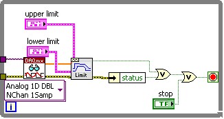
Hi all
This should be a pretty simple question, but I can't seem to find the answer online and currently do not have the functionality to test this:
I'm using LabVIEW 8.5 and have a VI that imports data from sensor through the DAQ Assistant. In the configuration tab, there is a range of signal input. What happens if my sensor exceeds this range? I get a warning? The default value is the maximum (or minimum)? I was interested in writing a code to display an error that I approach the limits of this range, but did not know if I also need to include code to display an error if the scope is exceeded as well.
Thanks for the help,
Tristan
Hello, Tristan,.
The behavior depends on the selected range and the device you are using.
If you are using a device with a single input range is valid, we will use this range, even if you set a smaller minimum and maximum in the DAQ Assistant. So, if your device only supports ±10V and you set the range to ±8V, you will still continue to get valid data after your top sensor 8V until what you approach 10V. When you reach the limit of the extent of your device, the output will be 'rail', and simply return the maximum value until the signal is less than the maximum value again.
Note: A device that is nominally ±10V usually has a go-around (such as ±10.2V) which are usually specced in the manual.
However, if you use a device with several ranges of entry then things become more complex.
NOR-DAQmx player will choose the smallest range that entirely covers the interval you choose. For example, suppose that your device supports the following input range: ±0.2V, ±1, ±5V, ±10V and you choose 0V - 3V as the range in the DAQ assistant. The NOR-DAQmx driver will focus on the input range and the list of the entry lines that your hardware supports and choose the smallest encompassing the entire range that you set. This would be the ±5V, because this is the only beach that contains up to 3V. Thus, all between ±5V input signal is returned and none outside this range will be 'rail' to the maximum or minimum value.
We do this because using small beaches make more efficient use of the resolution of the ADC. So, we try to use the most effective range based on what you ask without picking up a range that will make you miss data.
Let me know if I can clarify it more.
Maybe you are looking for
-
DesignJet z6100 PS: Serif Poster Designer cannot recognize Z6100 PS printer
The printer's IP address has changed. I've updated the properties of the printer to the new IP address. Windows 10 sees the printer and is connected. Print utility for HP sees the printer and gives me all the details, so I know that it is connecte
-
I bought an iPhone6 and transferred children 5 years to another rof my family member. Do you have all the changes (App, files, passwords). However, when I open iTunes on my Mac it still shows children 5 years and when I close and close and reopen iTu
-
Improvement/Bug? -Email always starts in the "Inbox all the»
I have two email accounts set up - an IMAP and Exchange. When I start the email it shows me always all messages in my Inbox. I would like to first of all it showing my default account (Exchange, in my case). Is this possible? If so, it's a bug or I'm
-
Hi all I have a simple code to send sms. It works very well. Just a glitch. How will I know that sms cannot be sent? Some timeout for the connection or otherwise? Let's say that if there is no network, no sim card or any credit. Thank you Here is the
-
Information on the phone connected through BIS
Hello I am facing a problem. So the problem that my app is communicating with the server in a blackberry connected to BIS. I tried to use deviceside = true, deviceside = false, interface = wifi, event without suffix, but nothing is. Unfortunately I d