Circle of scale on the graph XY
I found a post from 2005, showing how to draw a circle on a xy chart knowing the Center and RADIUS.
http://forums.ni.com/ni/board/message?board.id=170&message.id=146782&query.id=2708998#M146782. My xy grid is rectangular and Altenback mentioned a solution when your grid is not square, but I'm not able to follow. Any suggestions out there?
Thank you.
So to use the method "draw pictures. Have you looked at the example I quoted?
There are also many examples in the forum, for example here and here.
The above should help you get started.
Tags: NI Software
Similar Questions
-
Disable the change to the scale of the graph
Hello
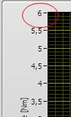
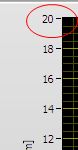
I want to block the scale of a graph on the front panel, which should display the y-scale of 0 to 6.
So I disable the autoscale y axis. But at run time I can always change the label max tick manually.
How can I lock the increment on the scale label without using the property node?
THX,
Wilbur
You have a property called editable in properties of scale Y of the graph than the value false.
-
How to read the values of the scale of a graph of intensity?
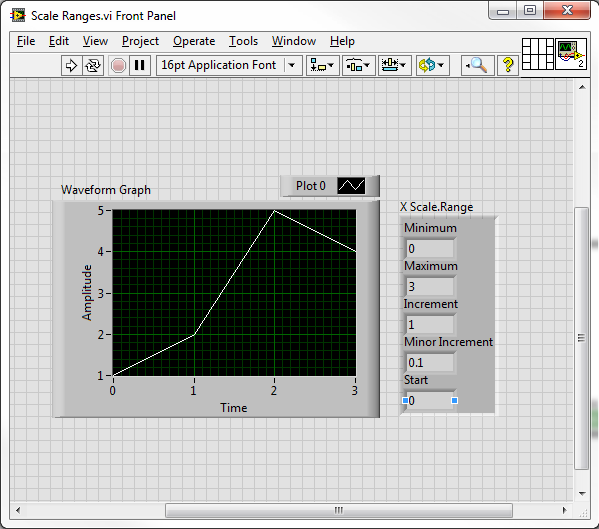
My goal is to read the scale varies (SHOWN Max and min values) of a graph of intensity.
I want to do a scan of a box, graphically display the result in the graph, zoom in on something interesting, and then use the zoom coordinates to define the area for the next analysis.
Is this possible and how?
If not possible, is there a work around?
Use the nodes property 'XScale.Range' and 'YScale.Range '.
-
How can I display only a part of the scale in the waveform graph
This is the first time I try to use the waveform graph, since now, I used the table of waveform.
The reason why I moved to the chart, it's that I need cursors.I have 2 problem
the first: in the diagram, the graph moves when I add a new data and the scale of the x-axis stay the same size, in the right size I always saw the new data. How can I do that with waveform graph?
Second: How do I say Labview to the day I click on the graph, I need that because when move graphic I lose the day, and to make I need to zoom out, I drag the imprecateurs.
All this must be done programmatically. The LabVIEW graphic accepts tabular data, not only as the table and the graph doesn't have the ability to retain the previous points, like the story of a graph. You will need to retain previous values and then continually update the graph with the old and new values to get a shift register "chart as behavior. Cursors should be written programmatically re of each iteration, since you rewrite the entire graph.
-
Vi transitional measure displayed in the graph of the wave are moving outside the scale
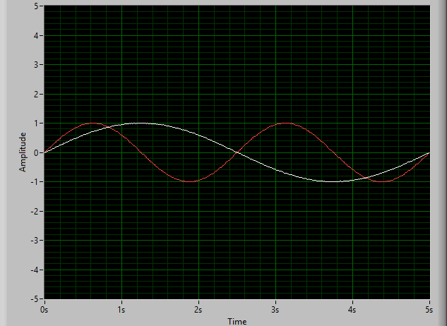
With the help of a graph of a waveform to display the pressure over time. I wanted to be able to calculate the time to drop in pressure over time, so I use the vi transitional measure. I copied what was exactly in the example for the measurement of transition inside help and it is correctly determine when to transition down, but I'm having a problem with the cursors in waveform graph. I would like to see a set of greenery along the fall time start and end time of fall as pictured, I have attached the vertical sliders (capture2) as in the example. The problem is the two always begin to 3.43 (capture1) and after each sampling period they (4.34, 5.34, 6.34) increment him come right out of all of the output of transition as these numbers measure. The period of the signal that I am interested is always less than 2 seconds, so I never see the vertical sliders.
I tried replacing it by my signal daq with an sine wave signal generator and it does the same thing.
The block diagram is in the first capture
also, I would be interested to know exactly how the numbers wired to the cursor property active of the property of a waveform graph node toward real sliders on the chart. They are just automatically numbered starting at 0 from the top down?
Wayland
Hi Wayland,
The sliders are still apparent in the example VI for the transitional Measurement.vi, is because the generated signal is always set to zero. Thus, signal resets a 'new' signal for the sliders to move and therefore always on the same location a bit. The waveform graph is also configured so that it won't move or continue to show new incoming data, data sliders have moved on. So in your case, you want to click with the right button on the chart and make sure that "Ignore Time Stamp" is not checked/selected. This will make it so the graph continues with your incoming data and cursors. You can check it in the example file by removing the constant True is the generator of signals and change the mentioned time stamp option previously.
In order to view the available sliders as well as their position numbered, you can right-click in the waveform graph and select Properties. In the Properties window, there is a tab of cursors, inside this tab at the top is a drop-down menu that lists all available sliders, indexed starting with 0 at the top.
-Jake B.
-
adjust the scale of the waveform graph
Hello
I have a graphic wavefrom receives two signals, can I adjust the scale of the y-axis of a signal?
Yes. You create a scale is double and set the plot of the new scale.
-
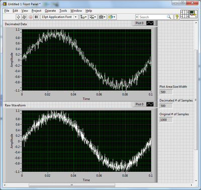
How the graph data are resampled pixels?
A test, I created two identical graphs with land areas 500 pixels wide and a noisy sinusoidal signal of 1000 samples. A chart displays the waveform right, while the other got the results of the use of the function Arrray to decimate to halve the number of samples. They are not the same.
Up to a waveform graph does exactly when it displays a data value larger than its width in pixels?
As you have noticed, the graph is a little more intelligent that you expected. When the number of points exceeds the number of pixels, a form any resampling must take place. A simple decimation as you tried would eventually pass some interesting points. Instead, the outliers receive priority when selecting which points to display. Strong in this way, peaks and dips appear even on a large scale. Reproduce this behavior yourself can be tricky. And once you reduce the data set, the points are gone and zoom is not as effective.
Usually, I try to let the chart to do as much as possible. A simple and effective way to reduce the size of the data you have to ship on the network is to use the SGL precision instead of double precision.
-
Precise timestamp on the graph of the band with scrolling
I have a user interface with a set of synchronized graphics that operate in mode scrolling stripchart. The elevator of the x-axis is visible on one of the cards, and the operator has the ability to take a break from the update of this table (essentially locking the entrance to the chart) and scrolling in a bit of history. The width of the graph is about one minute of data, the number of points has been set to allow about an hour to scroll of history. Other maps which are synchronized with the main chart have the x-axis property nodes attached, so that they follow the scrolling of the main graphic.
Everything works fine with the current configuration, except for one small detail: the timestamps. I put date and time stamping visible on the x-axis of the main graphic, so that operators know exactly when any aberration in the data actually took place. I have seen a few entries in how add real timestamp, but none of them seemed to work properly. They work very well on a standard sight, but fail miserably once the scrolling action is activated, so I have to do something wrong.
Any suggestions on the best way to get this accomplished timestamp? It's absolutely crazy to me how much pain is to put a timestamp to the real real world in a graphic... As someone who constantly defends LabVIEW against colleagues who claim that it is "too difficult" to use it, it's kind of embarrassing when a thing so simple becomes so complicated in LabVIEW!

The short answer is that this is impossible with a graphic if you add the requirement to be able to take a break. The reason is simple - a chart stores data on its own, but it saves all the values of X - you give only values Y and for the X values he simply uses the index of the value and the most you can do is set a t0 and delta t for the X scale. This works normally, but does not work when you stop feeding data to the chart, because the value of X is not stored. I heard someone say once a waveform graph does not allow this, but I've never looked into it and I'm not sure that's true.
What you can do is use a graphic instead of a chart - in a graph, you provide values X and Y for each point, so you can have absolute time for the x-axis values. The key point is that, to a chart, you must provide all the data to draw, you must maintain a circular buffer of the data yourself. You can do this by using a queue with loss, when you preview the queue to get the data, but there are also some examples online, as well as in the finder of the example, if you search for 'XY Chart'.
-
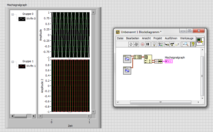
How to trace the temperature and voltage using the graph of Mixed Signal
Hello
I use the NOR cDAQ-9178, module NI 9214 (temperature) and the module NI 9201 (voltage). My program allows the user to choose among 3 different tasks, Masurement of temperature, voltage, or both. When you select the task for temperature and voltage measurement, I was drawing all channels on the same graph. I was invited to separate channels of temperature and voltage and draw on a split graph, using the same category axis. I tried stacking, but could not control where each parcel channel went. I think the Mixed Signal graph would work well. Everything works and records all the data of the channels to the files, but my plots appear not on the graph, although I can see the change in scale numbers. I think I can use the cluster incorrectly. Can someone tell me what I am doing wrong? I selected the 'Plot Visible' option, but the plot is not always displayed. I've attached a zip with all the screws needed to run my program. The main VI is "Voltage_Temperature_SingleTask_Measurements_MAIN.vi"... but everything must be downloaded to the program works. Please help... Thank you.

Hi mzhlb,
I complained only the expressVIs.
Why not use simple IndexArray function to get bots waveforms of your waveform table? (I faked it your DAQmxRead with functions SigGen).
-
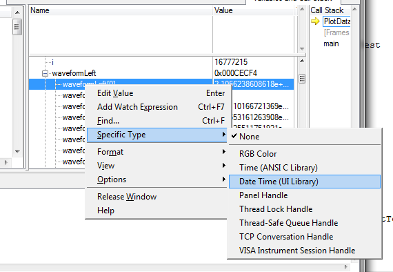
data is plotted on the graph of absolute time delay
Hi all
I'm plot data on a graph of absolute time and I find 2 hours difference between the data displayed by the debugger (left) and data on the graph (X - SCALE AUTO).
The time saved in ptTime, was acquired by using the function 'time' and the PC has Amsterdam, Berlin, Rome as time zone.
Here, under a screen shot that implemented the code, the debugger and the result.
The debugger is also showing the version in good time!
Can anyone suggest me how to process data in order to have the same result on the debugger window and on the graph?
A big thank you and best regards
Sergio
Question: in the CVI debugger show you, the time_t variable appears as a double, while its definition in 'time.h' is ' typedef unsigned int time_t; "so I am a little confused.
Response: I did something nonsense in this screenshot: I took a variable of type double (it happened to be a UIDateTime, actually) and configured the debugger to format as if it were a time_t variable. The formatted values that the debugger shows me, therefore, are not valid, of course. But I just wanted to show the time_t format, because it corresponds to what you have in your screenshot, and I was already suspicious that you use time_t variable to pass to the curve.
Furthermore, if you are not familiar with the way in which you can change the formatting in the debugger, this is how you do it:
Usually, the debugger can automatically pick the best format to use, based on the data type of the variable (for example, with variables of time_t). But in this case, what the debugger calls a variable "Date Time" is all just a double. The debugger cannot assume that you want to display all your double variables as a 'Date Time', and so you need to replace yourself.
Question: I was not able to find UIDateTime using the ICB type, this is the value returned by GetCurrentDateTime(double *)?
Response: There is really no such thing as a type of data "UIDateTime". I've been a bit remiss with my terminology. Unfortunately, when you're dealing with dates and hours, there are several possible representations of these quantities in the world of C, and it is important that you use the correct the intended variant you use for. In this case, the chart controls expect that you pass the time format used by the library of user interface, that is, one that is returned by the GetCurrentDateTime or MakeDateTime functions. The underlying C for this representation of the time data type is simply twice, and so it is not a good name to refer to it. That is why I used UIDateTime, but I should have been clearer than that.
Question: Y at - it a function to convert time_t values UIDateTime values
Response: Yes. You can use the functions of the programmer's Toolbox following two, in exactly this order:
CVIAbsoluteTimeFromCVIANSITime (time_t ansiTime, CVIAbsoluteTime * absTime);
CVIAbsoluteTimeToCVIUILTime (CVIAbsoluteTime absTime, double * uilTime);
-
Using an algorithm of scaling of the graph of a waveform within a Subvi invisible?
Hello
I have a little problem with the automatic scaling of the graphs.
First of all:
For automatic scaling of the axis LabVIEW uses the set of data that was sent to the curve. If I zoomed in on the inside, the automatic scaling always uses all of the data even if it is not visible at the moment. To resolve this problem, I read on the positions of the zoom sliders and values min/max within this area of research. This method works.
Second:
Now, I want to the scale of the axis using the specified min/max values. Labview graphics using a special algorithm of scaling according to the format of the axis. I want to use it, so my idea was to send the cut data and format of the axis to a Subvi. Inside this Subvi, I use a waveformgraph to display the cut data and run an automatic scaling once. Now, I read the values min/max of the graph and set this values on the main chart, I see in my program.
The result is, my main chart shows the data zoomed area in maximum size (to the axis scale) and hole data is always available, so I can still pass the data in the chart or others.
Problem: The sense of scale with a grpah inside a Subvi only works if the chart inside the Subvi is visible. If it isn't, no scaling would be made. My solution is to open the Subvi as a small window and close automatically after the scaling. It's not very nice.
Are there any other ideas how to use auto scaling without showing the front of the Subvi?
Thank you very much and best regards,
Michael
Hi Michael,
-show your façade out of the visible screen area, so the user does not notice the window...
-Make your own algorithm of scaling based on these values min/max...
-
I use X-zoom tool on the graphic palette. In this chart, the x-axis are time. Thus, for example, if I have 30 seconds displayed on the x-axis of the complete graph, and I want to zoom in on the Middle 10 seconds, how can I get the axis y data points that correspond to this average 10 seconds?
Similar to Cory's suggestion, could you use the X - Scale-> range-> the Min and Max properties to retrieve the appropriate data?
Maybe even link your sweater of data for the range of scale change event?
-
The scale of the maps of intensity color ramp
Hi all
I use a graph of intensity to draw the characteristics of an ultrasonic field. The measured values expand a range between 3, 0e-6 up to 12, 0e + 0, then I need a very well detailed verry color scaling. I found a beautiful image (http://zone.ni.com/devzone/cda/tut/p/id/7664) joint as an image "colors ramp.jpg precise", where the band of colors is reduced by the black-> green-> white-> blue-> green-> red. But with the "color table generator.vi" caused by only three points of features for each of the colors red, green, blue, I get only a scale like on the second picture "rough color ramp.jpg. It is not possible to scale of the ramp from black to green to white, then again for blue, green, red.
How can I get a color ramp as in "precise color ramp.jpg? I guess I need the possibillity of each of the red, green, blue nationally on more than three points.
Thank you very much in advance.
Hello...
I found the solution in http://decibel.ni.com/content/docs/DOC-9294.
The "Color Table" exit (U32 data type table) Create Gradient Color Ramp.vi can be connected to a node property graphic intensity with the property "color tbl".
Now, the ramp can be fitted with various colors, for example now a color tone can be used twice on the bottom of the ramp and the middle or on the top of the ramp again.
:-))
-
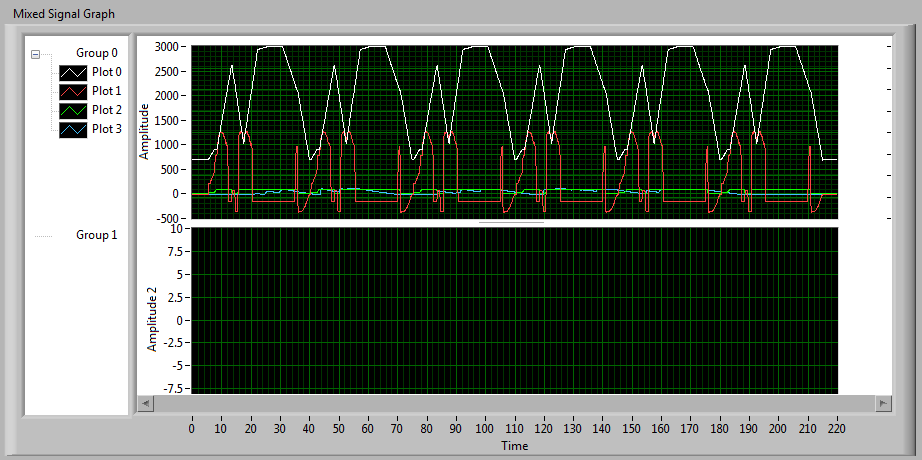
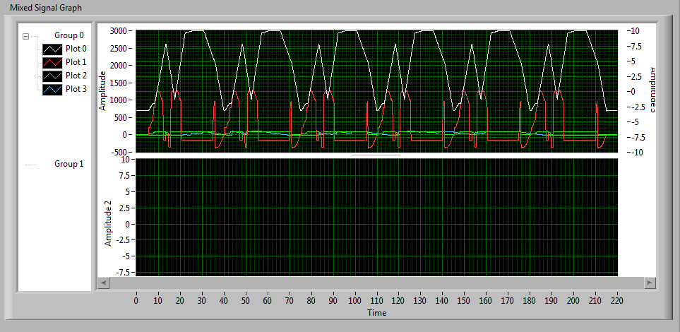
How do I return the scales on the Mixed graphic Signal?
LV 8.6.1f1
OK, so I look at the relatively new chart of MIXED SIGNALS to fix things that don't work on the regular chart (more precisely, the weird cursor behavior).
It seems I have a slider that spans four plots and reads an X 4 values of Y, that's what I want.
But I need ladders on both sides.
I tried to create the 2nd scale and the SIDES exchanged with her and got this:
There is no ladder on the right?
Or is it?
These graduations few are a clue.
I so stretch the right side of the chart and guess what?
There is the scale:
In other words, the new graphic scale left anywhere on the screen, even if I resize the chart horizontally.
I can move the chart, the scale moves with him. I can re-size on the left, and the left scale shows the same effect.
It seems to me that graphic scales must be attached to the plot area.
This graph is a TAB control, maybe the problem is related to this error of LabVIEW.
Or am I missing something?
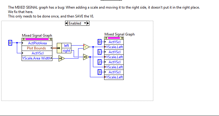
Here is the code I ended up with difficultytowork around this problem.
Mixed-Signal graph has ANOTHER problem where he completely forgets your assignments whose plots go on the scales, but that's another story.
In my case, I've already placed the scales on the sides left / right as needed. It's just that the right bottpm scale, really, really wants to be off to the right.
What I do here, it's fetching the LIMITS of PARCEL of land #0 (the top one).
I'm only interested in the left-right axis, I don't have a problem vertically.
Also, I extract the AREA of scale 0-WIDTH WIDE.
I then adjust the YSCALE. LEFT property of the four scales, place them where I want.
The two scales on the LEFT are the BOUNDARIES of the PARCEL. -LEFT (WIDTH + 1 ON THE SCALE)
The two scales on the RIGHT are to DRAW the BOUNDARIES. RIGHT + 1
The "+ 1" means there are a pixel between the scale graduation mark and the border of the chart itself. I think it's better.
Just run the VI once to run this code, then turn off the code section and save the VI. (You do not need to run it again unless something changes, he seems to remember where it is supposed to be).
Of course, if you resize the graphic, you will need to run the patch again.
-
Change the graph with nodes of property
I've been struggling with this problem for a while now. I have a graph of simple waveform I want to set the horizontal scale to and then make a .png to file. The vi is attached. This vi is up to a lot more great vi. Does not work when I run the first level vi of the adjustment of the horizontal scale. The .png file I receive shows the unadjusted graph. However, if I open this vi and then run the first level vi it works - the graph shows the .png file scale properly. Also, if I just run this vi se it works correctly.
I'm guessing there is a timing issue and the .png file is created before the scaling takes place, but I don't see how.
Does anyone have any ideas as to why the scale does not if the vi is not open, when it is executed?
If the front of the VI is not open, the nodes property can do nothing because they run in the UI thread. This is consistent with the behavior you report with it works when the VI is open.
Can you try to open the façade but putting off the screen (if the user does not see it) and then set the properties of the graph?
Lynn
Maybe you are looking for
-
Satellite R630-146 does support disk HARD SATA II (SATA-300)
Hello I intend to change my current HITACHI 5K 320 320 HARD drive (HTS543232L9SA00), which is SATA I (* SATA-150 *) on the new HARD drive, but I can't find all the information my Toshiba Satellite R630-146 will support the new SATA II (* SATA-300 *)
-
I recently added some things and I've lost my things on the bottom of my screen modzilla, internet exployer and outlook express and I do not know how to get them back, I have not removed the programs that they are simply not on the screen when it is
-
Computer does not recognize my MP3 player.
My Trekstor MP3 player has the USB Hub, but the computer is not recognized as a drive or device. I reinstalled Trekstore software nothing works. I also tried on my brand new laptop at work running on XP and had the same result.
-
Where can I find a driver for Sony PEG TJ37?
Original title: PEG-TJ37 need a driver for windows vista for sony clie PEG-TJ37
-
Original title: Operation canceled When you click on a hyperlink in an e-mail message, I get this Message: "this operation has been cancelled due to restrictions in effect on this computer. Please contact your system administrator. "I get this messag