Command PID made al control of DC motors
Hola a todos
Alguien me could asesorar con el uso del PID toolkit there that manera lo puedo more al control of 2 DC motors, con doble cuadratura encoders
Buenos dias, Diego,
SIGA el enlace para descargar el PID Toolkit. Any pregunta por favor póngase in contacto con nosotros.
LabVIEW PID and Fuzzy Logic Control Toolkit 6.0 - update for LabVIEW 8.0 - Windows
http://Joule.NI.com/nidu/CDs/view/p/ID/603/lang/en
Carefully,.
Tags: NI Hardware
Similar Questions
-
Note: I know that this post can be considered off-topic, but I think my problem is with how I'm trying to control my instrument (not the PID controller); That's why I posted my question here. Please correct me if I'm wrong.
Seen: I have a power supply programmable dual channel, a wheel and a PID controller.
Find: The encoder feedback, I would like to use the PID controller to control the outputs on my power supply.
My solution
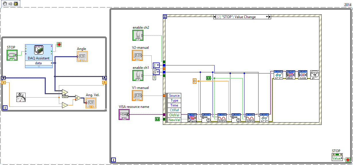
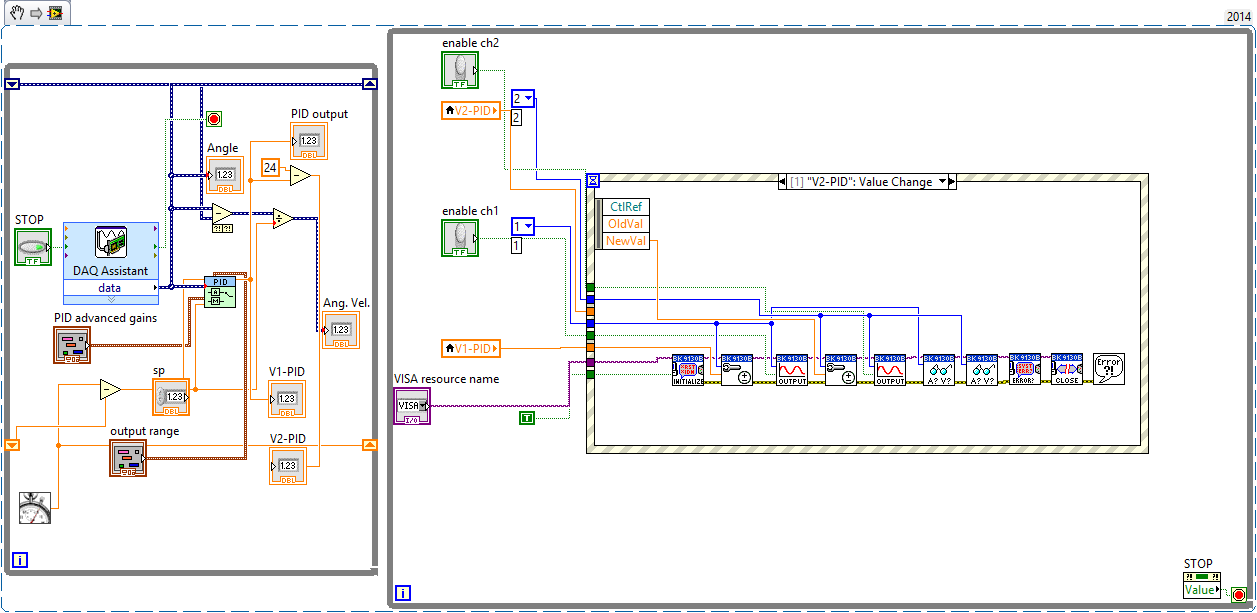
Using the VI below, I can read the encoder and adjust the power supply without a regulator PID. The left loop reads the encoder data, and the loop on the right allows me to "manually" resolve tensions on the channel 1 and channel 2. Specifically, a structure of the event inside the loop on the right send recent tensions 'channel' (as I entered in the respective controls) power supply.My problem
However, the law while loop is not "react" when I can replace this "manual" voltage control a PID controller. The power supply simply does nothing even though the PID is indicative of the power to do something.Attempt to correct
Mode "highlight execution", I noticed my left loop would complete many iterations, but data in the loop on the right had to run only one time - and even in this case data arrested when he reached the structure of the event.Questions
- My PID control loop does not work because the PID loop (left) runs too fast compared to my power supply loop?
- What would you recommend? Filers?
- (Slightly unrelated) How should I wait the last strains of my diet?
The two blocs 'read out' in the loop of power should allow me to display the real tension of a channel. However, these data are always a 'step' behind the actual reading.
For example, I put V1 = 12V. Food reacts and displays 11.998V on its LCD screen. However, my LV code displays 0V (or any busy V1 value). If I change again V1, say V1 = 7.9V, then the power displays 7.989V but the code LV displays 11.998V. What I am doing wrong?
Writes that if I set V1 and then set V2, my LV code displays the value of the V1 correct but not the last value of V2.
Well, the first problem is obvious. You initialize the power whenever the event occurs. (DON ' T DO THAT! ")
Initiallize ONCE
Loop ON
Read the answer
Feedback monitor
Adjust the stimulation
until the output is requested
Output control loop
Close resources ONCE
-
What is fledge command-line argument to control the graphics acceleration?
Is there a command line argument to control the graphics acceleration for a JDE 5.0 Simulator?
I would like to switch off in the command line so I can add it to the Simulator Run Eclipse IDE and the debug configuration.
I checked their moult imaginal/Help and I have not found any that I could see that it works.
Thank you.
The settings are stored in a file located at
\Documents and Settings\ [windows login name]\net\rim\fledge-2\fledge-saved.conf
At the bottom of the appearance of file for the line:
Change the number 0 for no acceleration.
-
control of DC motor using myDAQ
Hello
I'm building a DC motor using myDAQ command, that I ran into a couple of problem with the STOP button and the Max speed Min. For some reason, the diagram of waveform becomes crazy I will attach my file VI.
Description of the project:
-An engine-engine-OFF button
-A control for fast / slow
-A switch left / right
-A speed once button maximum (100)
-A speed once button minimum (10)
-An indicator of instantaneous speed (0 - stop, maximum 100)
-An indicator that signals the directionCould someone tell me why it happens and how to solve the problem?
Thank you very much!
Best,
Istrael
Hi Istrael,
You use a lot of CPU resources by not including not calendar in your loop. I think that your questions can be resolved if you place a timer 'Until the next ms Multiple' in your 'pulsegenerate.vi' in a loop. This will actually load on your CPU if you set it to 1 ms.
I hope this works,
Paul
-
control of DC motor speed with a controllable power
I'm looking for a way to control a "toudeft PL330P Thurlby" controllable power in labview. My knowledge of labview is very little and I'm sure that's probably not so difficult. I need to be able to vary the tension passes to food so that I can control my motor speed continuous.
I plugged the power supply via a GPIB interface cable. (OR-488. 2) and I'm using LabView 8.5.Dose anyone know how I would go all this? Or could provide useful examples.
Thank you.
James.
Get the driver LabVIEW using ' help > find Instrument drivers... ". "or here: http://sine.ni.com/apps/utf8/niid_web_display.download_page?p_id_guid=E3B19B3E97F2659CE034080020E748... "
I didn't load them, but usually there are a few simple screws to send commands to your hardware. ALWAYS look for drivers of instruments for the new hardware. It allows you to save a lot of tedious work if they are available.

-
PID tuning - temperature control
Hello
I'm working on a project of PID control with a dreaded heating control. The radiator is small enough ~ 10 watts, so the response time is very fast. My set point increases, my HP decreases. I'm controlling the radiator with a continuous feed, so the nominal value is an environment of tension and I left PID +/-100% 0 voltage swing at full scale.
The Kc is of about 0.4.
With a control P, Kp = 0.2, I get a damped oscillation, which hovers at about 2-4% higher than the set value.
With IP control, Kp = 0.2, Ki = 0.00001, I get a constant oscillation around the setpoint.
An example with PI control is attached. It seems that my sample rate is too slow (the PV and SP are made with GPIB).

The sequence of events is--> order SP-> (wait)--> PV read--> PID use to set the new SP--> (loop)
I tried to improve it by putting the measure of PV in a parallel loop. This seems to help some, but does not eliminate the oscillation. Old time loop was ~ 0.3 seconds, now it is 0.15 seconds. Faster and my loop time< pv="" measurement="">
Any suggestions? I tried the Autotune PID vi, but he could never solve the system.
I've done a few things to improve the response:
1.), I use a PID of two floors. The "inner loop" PID control constantly power from 0 to full scale. The "outer loop" adjusts the power + / to reach the set point. (fine adjustment) Each PID loop has its own set of PID parameters.
(2.) for some reason, control PID never worked well because my point was inversely proportional to the power. I created a formula that has converted my set point to a function which is proportional to the power in watts.
-
Hello. I have a problem with a prototype of movement control, and I am at a loss to know where to look next.
I run a computer running Windows XP with LabVIEW 8.6.1. The computer contains an NI PCI-7332 motion controller nine connected to a card NI UMI-7772 control a P70360 stepper drive. I'm trying to run a command of CTP 11 ELF 11 Danaher engine with little success.
All the lights on the boards are the appropriate color. I followed the implementation of the steps in "Getting started: P7000 series Stepper Drives. I have the correct indicators in the interface of MAX, and I can not even the motor to hum a little when I press 'Start', but the axle does not turn. I check the wiring of the driver of the engine and both Multimeters and diagram agree that, at worst, to run it back. This is before any programming LabVIEW. I'm just trying to make the engine start with MAX.
Any help would be greatly appreciated as this is my first time setting such a system.
Ben
Hi Ben,
Looks like your engine, and if your player are not compatible. 11 ELF 11 CTP is supported by the P70530 and not by the P70360 (see table 5 in the P7000 manual start-up). The P70360 (320 V) bus voltage is too high for this type of engine. Please contact your local branch OR for redemption for the right hardware options (you will need to swap the drive or motor).
In addition, I highly recommend using the software tools P7000 in combination with a cable (P/N 780099-01) series to set up the reader. It gives much more flexibility to use switches dip and you can optimize the performance of the drive and motor by adjusting the inductance of the individual motor drive.
Kind regards
Jochen Klier
National Instruments
-
Control of Stepper Motor with case NI USB-6009
Hi all
I am currently creating a movement control system with a double movement actuator
and two bipolar chopper drives (see table), which should power the motor. We already have a NI USB 6009 in our lab, so I was wondering if I could use it to send signals to the two pilots to control the speed and direction of each axis on the engine?
Enclosed driver's manual indicates that input signals should be 0-5 V DC (TTL logic). I have been informed by the engine distributor that the 0-5 V DC TTL drivers required, the signals are analog. The NI USB-6009 manual reading, there are two 0-5 V analog outputs on the acquisition of data usb so I could provide two signals?
There are often posted however similar problems, it is usually a digital signal NI6009/6009 sends the driver. Looking at the driver's manual, can someone tell if an analogue signals or required as I have said, I was misinformed or 0-5 v DC signal will be enough. I can get more in touch with the dealer if you have any questions you guys think I should ask him.
Thanks in advance for any help! It is much appreciated.
I looked in the manual and it doesn't seem to be very clear. I know that the USB-6009 case is capable of AO and DO, then you would be although it is. I could contact the Haydon Kerk support for more concrete details on the gap between what says the manual and what they told you.
-
How to control an electric motor using LabVIEW?
Hello
is there a simple way to control the rotation speed of an electric motor (12V) using LabVIEW?
I have an idea how to achieve this using the card OR measurement, its not that cheap. Any ideas?
Maciek.
-
Help required with control PID for RPM control application
Hi guys,.
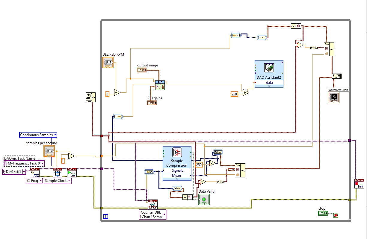
I worked on this project for a while that I started from scratch. Here's the idea: the centrifuge of the computer in the control, use the analog output voltage, meter of entry to get the frequency of rotation. Optointerruptor is defined as the frequency measurement is exactly the same as the number of TURNS. I tried to create a loop to output test voltage and he took in the acquisition of data to test everything and determine the gains of PID. As everything worked well, I went to the entrance of counter to test the model in reality. I faced following problem: task does not run on virtual meter inlet channel. If I don't get in the loop of PID process variable and anything not working as it should.
I have attached an excerpt from the code of the entry of counter as well as one of the control loop that worked very well. Maybe you can point me in the right direction. Thank you!
Best wishes
Mariia
Have you ever had the counter entry work? Build a simple program that reads only from the entrance of the meter. It work? If this isn't the case, you get an error in the DAQmx screw? If so, what is the error? If not, what is the result of the DAQmx Read? You can connect your input of an oscilloscope to verify that your hardware is properly production of pulses?
-
Closed the motor current continuous Brushless PM and the loop speed control of Induction motor
I need to implement the speed control of motors, asynchronous Motors PM Brushless DC and several other algorithms of cardiac control using LabView. It will take me 6-channel PWM and 6-channel 12 bit ADC, and a control movement of VI. Ideally a DSP would do the trick, but I would like to take advantage of the user-friendly interface of the LabView program to reduce development time. Please suggest the best hardware solution.
Vaszzy,
the SCB-68 is just a connection for the 7842R block and it does not provide a conditioning of signals. You can use digital IO of the RIO card to generate PWM signals. The 7842R provides converters a/d for voltage measurements. To measure the current you will need high precision resistors to convert current into voltage.
Kind regards
Jochen
-
I'm under Windows Explorer from a command line under Vista and 7. Under XP I could use the /n switch to control or not display the navigation pane. This doesn't seem to work on later operating systems. How is it possible?
Hello
How to change Windows Explorer icon to open a folder in Windows XP and Vista Diffierent - this shows the
command line and that the switch should always work.
http://www.watchingthenet.com/how-to-change-Windows-Explorer-icon-to-open-a-diffierent-folder-in-Windows-XP-and-Vista.htmlCommand line switches to display items or folders when you open Windows Explorer
http://www.mydigitallife.info/2009/02/07/command-line-switches-to-display-special-objects-or-folders-when-opening-Windows-Explorer/I hope this helps.
Rob - bicycle - Mark Twain said it is good. -
Hello world
It is a long shot, but I can explain my problem and I hope that someone has seen this problem before.
PROBLEM:
I use a rotation of Newport PR50PP turntable that is controlled by a motorcontroller SMC100PP through LabVIEW. In my experience, I shoot the scene 180 degrees to the right in increments of 36 and then turn to "zero" counterclockwise. This "zero" point must be the same 'zero', I started to leave before the rotation. The problem is that it is off by nearly a whole degree. I need to always start in the same place.
The big problem - computer / Platinum rotation it's originally 'zero '. I record the unit of internal rotation of the scene after each movement and he tells me it's the same 0.00 that began.
Q: is this a problem of communication between LabVIEW and the PR50PP or a mechanical problem?
OTHER NOTES:
- The change of rotation is repetitive and linear. I repeated more than 15 times and got about the same offset.
- How I discovered this problem - I have a half plate on the rotation stage and looked between cross polarizers. I recorded the Cos ^ 2 model of intensity of each scan. Each pattern is rotated to the front even if the computer reports that they should be at the same position.
- I'm under LabVIEW 2011 and by using the controls provided by Newport SMC. They communicate via USB of series.
- Joined a technical description of the problem that my labmate written upward.
Any idea is appreciated.
~ Liz Cloos
Hello world
After running additional tests, I discovered that it is NOT a problem of LabVIEW. The plate wave inside the rotation of PR50PP plate was a little loose and gave the appearance that the zero is changing. The ribbed plate kept turning slightly after each change of direction.
Thanks for trying to help.
-
In what order are anchor command left and right control point values returned by entirePath()?
The entirePath() returns the anchor points that have two values, or it returns an array with three coordinates. I would like to know, in this case, what is the point of anchorage, control point index and values of point of order from right to left?
The three values are leftDirection, the point of anchorage and directed. 'leftDirection' and 'directed' compete in the competition for the worst property names, because they have nothing to do with the left and right. Publishers of fonts and other programs that deal with the use of the perfectly transparent Bezier curves "in" and "out." These words make sense. Adobe of not.
To find out what values stand for, draw a simple curve with three points, then use a script to write the values to the console of the ESTK. Open the transform Panel and check the values it that that you printed in the console.
A major problem in all of this, is that when you select a point with the direct Selection tool, app.selection [0] does not return this point (I forget now what it returns) and get a handle on a selected point is an ugly hack.
Peter
-
My old top bar has buttons for
Display of file change... Help
Send the spelling... SaveI did something while answering an e-mail that makes that all the top bar disappear, not I have to click ctrl - enter the body to make an email to send, I can not add an attachment without having to type "attachment" in the text to get the ability to add, etc..
I would like the old arrangement, I think that it has always been that the default back if possible, cannot understand how do...
Thank you!
Charley tart
In the entry window menu bar:
Display - toolbars
Check the 'Composition Toolbar'.
Maybe you are looking for
-
24.0 Firefox crashes consistently?
After that automatically put Firefox updated to version 24.0, he was constantly crashing. I tried to uncheck 'use hardware acceleration when available' and do javascript.options.baselinejit.content, javascript.options.baselinejit.chrome and javascrip
-
Facebook doesn't work does not correctly in 14.0.1
Since the 14.0.1 update (maybe a 14 precedents), I could not post, or even ' like' items on Facebook. I can read pages fine, but am not able to grasp anything. I get a Facebook page that says, oops something does not etc. However, if I switch to IE,
-
Toshiba Camileo H30 SD card format?
Hello I have a Toshiba Camileo H30, and if I record more then 40 minutes, the camera will be 2 separate files. Is it because of the file format? The SD card is formatted in FAT32 formatted by the camera. I know that in FAT32, the biggest file can be
-
Server 2008 r2 Regestry key merge to a wrong setting
I am rebuilding a Server 2008 r2 Enterprise full installation. I have a new and unusual problem merging registry keys from my old server running 2008 r2 Enterprise full installation as well. When I merge the keys he come back successful, but the serv
-
I spent too much time trying to do. When I 'Browse' for printer, it does not work, I do not know "computer / / printer...» "I don't know how to find the 'URL '. I have searched the HELP (?) with no results, in fact, when I search help and ask a very