control of DC motor using myDAQ
Hello
I'm building a DC motor using myDAQ command, that I ran into a couple of problem with the STOP button and the Max speed Min. For some reason, the diagram of waveform becomes crazy I will attach my file VI.
Description of the project:
-An engine-engine-OFF button
-A control for fast / slow
-A switch left / right
-A speed once button maximum (100)
-A speed once button minimum (10)
-An indicator of instantaneous speed (0 - stop, maximum 100)
-An indicator that signals the direction
Could someone tell me why it happens and how to solve the problem?
Thank you very much!
Best,
Istrael
Hi Istrael,
You use a lot of CPU resources by not including not calendar in your loop. I think that your questions can be resolved if you place a timer 'Until the next ms Multiple' in your 'pulsegenerate.vi' in a loop. This will actually load on your CPU if you set it to 1 ms.
I hope this works,
Paul
Tags: NI Software
Similar Questions
-
How to control an electric motor using LabVIEW?
Hello
is there a simple way to control the rotation speed of an electric motor (12V) using LabVIEW?
I have an idea how to achieve this using the card OR measurement, its not that cheap. Any ideas?
Maciek.
-
Hello world
I have a very simple problem that gives me a lot of trouble. I'm trying to run an engine on the analog output of a device of acquisition data NI USB-6211. I wrote a simple test code using the express VI and DAQ VI signal to control the motor. While the output graph displays the waveform that I need to control the stepper motor, the motor does not move. When I activate the program I can hear the motor buzzing, very faintly, that tells me that the program works and the engine is triggering correctly but there is not enough power for the engine to recharge the batteries. Given that my motor needs + / 3, 2V to trigger the so-called DAQ outputs hardware up to +/-10V (and) I don't think that the voltage is the problem. The only thing I can think is that the DAQ hardware is not really this output voltage, but I don't know of anyway to check.
If anyone has any ideas on how to solve my problem, it would be a great help.
I also downloaded my VI for reference.
Well, you check the voltage with a voltmeter.
Have you looked at the current requirements? You think there is not enough power and power is equal to the time of current tension. That said the spec 6211 is the maximum current output?
-
Please return shot single finger upward to access other applications. Control Center should be dedicated to side button that requires two finger access. At least give user option to choose which method to use to access the Dock or Control Center. After using for a year watch am now forced to use apps on a daily basis in a less convenient way.
Hello
It is a community of user-oriented support.
If you wish to submit a feature request to Apple, you can do so here:
-
Possible tree CVI control without a mouse, using SW
I received a CVI application that includes a panel with a section of tree control. The task I have to do is to try and automate the current software application to exclude the manual use of the mouse. Anyway is at the interface of a 'tree' by using a gentle approach and not the mouse?
If you want to run on the control programmatically you can use the features included in this page; to expand or collapse a tree branch for example you can:
- Navigate to the item in the tree to work on with GetTreeItemFromTag (panelHandle, PANEL_TREE, "thetag", &idx);)
- Set its State with SetTreeItemAttribute (panelHandle, PANEL_TREE, idx, ATTR_COLLAPSED, 1);
But I feel that your concept of automation of the program is the ability to operate on the program of a different application act as if it were the user. If this is true, I fear there is no possibility to do so, as control CVI are not standard windows controls (for example, you can get their handful of system).
-
Constant voltage using myDAQ output
Im a student and I'm using myDAQ for my final project, I have buil year VI and I want to add a constant output of 3, 3V, during the course of the VI.
searched the forum, impossible to find something with myDAQ.
Here's my VI:
Just put a new assistant on the diagram of block and instead of the acquisition, select build from the beginning. Choose your channel. Select 1 sample. Wire your constant Assistant.
-
Control of Stepper Motor with case NI USB-6009
Hi all
I am currently creating a movement control system with a double movement actuator
and two bipolar chopper drives (see table), which should power the motor. We already have a NI USB 6009 in our lab, so I was wondering if I could use it to send signals to the two pilots to control the speed and direction of each axis on the engine?
Enclosed driver's manual indicates that input signals should be 0-5 V DC (TTL logic). I have been informed by the engine distributor that the 0-5 V DC TTL drivers required, the signals are analog. The NI USB-6009 manual reading, there are two 0-5 V analog outputs on the acquisition of data usb so I could provide two signals?
There are often posted however similar problems, it is usually a digital signal NI6009/6009 sends the driver. Looking at the driver's manual, can someone tell if an analogue signals or required as I have said, I was misinformed or 0-5 v DC signal will be enough. I can get more in touch with the dealer if you have any questions you guys think I should ask him.
Thanks in advance for any help! It is much appreciated.
I looked in the manual and it doesn't seem to be very clear. I know that the USB-6009 case is capable of AO and DO, then you would be although it is. I could contact the Haydon Kerk support for more concrete details on the gap between what says the manual and what they told you.
-
control of DC motor speed with a controllable power
I'm looking for a way to control a "toudeft PL330P Thurlby" controllable power in labview. My knowledge of labview is very little and I'm sure that's probably not so difficult. I need to be able to vary the tension passes to food so that I can control my motor speed continuous.
I plugged the power supply via a GPIB interface cable. (OR-488. 2) and I'm using LabView 8.5.Dose anyone know how I would go all this? Or could provide useful examples.
Thank you.
James.
Get the driver LabVIEW using ' help > find Instrument drivers... ". "or here: http://sine.ni.com/apps/utf8/niid_web_display.download_page?p_id_guid=E3B19B3E97F2659CE034080020E748... "
I didn't load them, but usually there are a few simple screws to send commands to your hardware. ALWAYS look for drivers of instruments for the new hardware. It allows you to save a lot of tedious work if they are available.

-
Closed the motor current continuous Brushless PM and the loop speed control of Induction motor
I need to implement the speed control of motors, asynchronous Motors PM Brushless DC and several other algorithms of cardiac control using LabView. It will take me 6-channel PWM and 6-channel 12 bit ADC, and a control movement of VI. Ideally a DSP would do the trick, but I would like to take advantage of the user-friendly interface of the LabView program to reduce development time. Please suggest the best hardware solution.
Vaszzy,
the SCB-68 is just a connection for the 7842R block and it does not provide a conditioning of signals. You can use digital IO of the RIO card to generate PWM signals. The 7842R provides converters a/d for voltage measurements. To measure the current you will need high precision resistors to convert current into voltage.
Kind regards
Jochen
-
Hello. I have a problem with a prototype of movement control, and I am at a loss to know where to look next.
I run a computer running Windows XP with LabVIEW 8.6.1. The computer contains an NI PCI-7332 motion controller nine connected to a card NI UMI-7772 control a P70360 stepper drive. I'm trying to run a command of CTP 11 ELF 11 Danaher engine with little success.
All the lights on the boards are the appropriate color. I followed the implementation of the steps in "Getting started: P7000 series Stepper Drives. I have the correct indicators in the interface of MAX, and I can not even the motor to hum a little when I press 'Start', but the axle does not turn. I check the wiring of the driver of the engine and both Multimeters and diagram agree that, at worst, to run it back. This is before any programming LabVIEW. I'm just trying to make the engine start with MAX.
Any help would be greatly appreciated as this is my first time setting such a system.
Ben
Hi Ben,
Looks like your engine, and if your player are not compatible. 11 ELF 11 CTP is supported by the P70530 and not by the P70360 (see table 5 in the P7000 manual start-up). The P70360 (320 V) bus voltage is too high for this type of engine. Please contact your local branch OR for redemption for the right hardware options (you will need to swap the drive or motor).
In addition, I highly recommend using the software tools P7000 in combination with a cable (P/N 780099-01) series to set up the reader. It gives much more flexibility to use switches dip and you can optimize the performance of the drive and motor by adjusting the inductance of the individual motor drive.
Kind regards
Jochen Klier
National Instruments
-
for control voltage can we use usb-6001?
where can I find the usb-6001 software and driver?
You can certainly use a 6001 to control the tension... in line with the specifications of the device.
Driver belongs to DAQmx, available here: http://www.ni.com/download/ni-daqmx-14.1/4953/en/
-
generation of clock using mydaq
Hello world!
I just have a very BASIC question. I know that some of you may find it easy.
Again, I'm new in LabVIEW and I try to use a data acquisition equipment NOR myDAQ. In the application, that I'm doing, I need to get a pulse generating myDAQ signal and use it as input in my multiplexer. I searched for positions and I think that none were asking such a simple question.
If there is no solution for this, please link with me. Thank you very much!
Kind regards
Falsehope
FalseHope wrote:
I am afraid that I can not do. I'm only using the computer lab of the school and he removed the LabVIEW examples folder (perhaps to prevent students to access the examples during the reviews of practices). So yes... I am a student with limited access to LabVIEW.
But I talked to the it DEPARTMENT of our school and it allowed me to download the examples instead. However, I can't find the codes available.
Kind regards
Falsehope
IMHO, he is a stupid thing, a good teacher can create easily of exercises and tasks of review to "measure" the real knowledge of the students, even if they use the built-in LabVIEW examples. A school should help during the learning curve and not by disabling the examples incorporated, but giving creative tasks...
I've attached an example VI that will generate an output of 1 kHz by DIO-3 and DGND counter. (I tested with a myDAQ device, it works)
-
Command PID made al control of DC motors
Hola a todos
Alguien me could asesorar con el uso del PID toolkit there that manera lo puedo more al control of 2 DC motors, con doble cuadratura encoders
Buenos dias, Diego,
SIGA el enlace para descargar el PID Toolkit. Any pregunta por favor póngase in contacto con nosotros.
LabVIEW PID and Fuzzy Logic Control Toolkit 6.0 - update for LabVIEW 8.0 - Windows
http://Joule.NI.com/nidu/CDs/view/p/ID/603/lang/en
Carefully,.
-
How to control the mouse cursor using EEG signals
Hello world
I am doing a project of cursor control using EEG signals. The idea is to find a way to all signals in a specific period of time in order to find the signal Ridge. Then, the highlight will be a parameter to control the position of a cursor.
Can someone tell me the function that allows you to control the mouse cursor?
I also found an old topic asking about it (http://forums.ni.com/t5/LabVIEW/Moving-Mouse-using-Labview/td-p/1285842) and I run an example of this link ( smercurio_fc) program. My cursor is stuck in the upper left corner of the screen, I can't control it again. Can you tell me how to run this program and to use the windows API?
Thank you in advance.
Sorry, but I can't do it for you.
As I advised, you should take the free online tutorials. You clearly lacks the basic concepts of LabVIEW, as data flow.
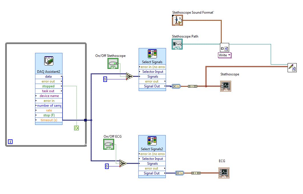
Things more: in your real applicaton does not use DAQ Assistant, screw Express are generally not optimal for data acquisition. It is safer and better use good DAQmx live. What is the equipment you use? Sampling rate, etc.?
Why do you need to read data files? For testing? I thought that you will acquire data active, right? In your VI generate you some signals and write in a data file. Is this also for testing?
There are several constructs in your VI which simply don't make sense.
So again, I really suggest to go through online Core1-2 teaching material, which is accessible if you are a student, or if you have shared services provider license... It will really help.
-
I can't launch the stepper motor using NI 9501 with the example given.
I have a NOR cRIO-9025. I'm trying to run a motor drive with NI 9501 with the help of the given example (Veloity control (open loop) - NI 9501). The program is compiled on the FPGA, but the motor step does not move. The poster drive status always "disabled by software. What I am doing wrong? I'm under the RT and FPGA live
Hi Pranjal,
You will need to provide an external power supply to the module. If you look at the Manual 9501, you will see that the pins 7 and 8 are intended to power 8 - 30V. If you do not connect this offer, you will have a fault and the Red led should light up. The manual shows you different ways to connect your motor.
When you run the VI, you will want to run only the RT VI. The FPGA VI will run automatically when you start the RT VI.
You are right that there is no file "Items to Move. Instead, you want to spend the following things to your new target: speed control (open loop) - .vi NI 9501 (RT), speed control (open loop) - .vi OR 9501 (FPGA) and the target value. You want to make sure that you drag to the appropriate hierarchy. The RT VI must be less than the RT controller in the project and the FPGA VI and set FIFO must be below the target FPGA. Finally, you want to make sure that Mod1 is a 9501.
I would like to know if any of this helps.
Thank you
Maybe you are looking for
-
missing a few previously purchased songs (!) and i-tunes helper does not
I keep getting errors during a new playlist, saying "file not found". So I tried the recommended - diagnostic tests that shows "I-tune helper does not ' is the two partners? How can I find the missing music and recover my account?
-
Hp500-319NA I5: Hp 500-319NA I5 600w power supply suggestions
I am looking for a diet that will end in my case, because I just ordered a new graphics card (nvidia gtx 750 ti Gets) who need a supplement of 400 watts of power. I would like if someone could recommend any food for my problem
-
When in the Background Intelligent Transfer Service is activated, only the system hangs for about 20 minutes after the connection to dial up the internet connection. But if I disable the BITS, this problem did not appear. My OS is windows server 2012
-
Ranging from the wired wireless and vice versa
I have users who have laptops and connect to the network via a cable, and then decide to leave (as due to a meeting), so that they log off and back on the radio. Then, at some point, they decide to reconnect. When they do, they lose the connection
-
Blocking Windows Explorer when you click on "organize".
Everthing work fine until you click on "organize" folder what ever you are at will not respond.