compile the waveforms digital en port0/line1
Hola
Estoy intentando building una salida digital (waveform) don't con una 6624, if utilizo el puerto0/$line0 the output is genres correctamente, if utilizo el puerto0/line1 no none veo Señal. ¿alguien sabe has that're due?
Gracias por adelantado.
Solved, fallo mio al understand como Digital works 1 d 1 U32 Chan NSamp, thought that solo is enviaban 0 y 1 a puerto in vez al of that esos numbers en binario indican el estado del number del puerto.
Tags: NI Hardware
Similar Questions
-
Send the meter digital outputs while gaining analog data
Hi all
I'm looking to acquire analog inputs on several channels and send simple TTL pulses at different times during the acquisition using a Board from UBB-6221. Delays at the outset of the acquisition and the release of life should be handles by a control on the front panel. I got it work using the software timing and an inexpensive board before, but the program needs to be more specific than that (so timing equipment). I write the program using DAQmx and LabView 8.2, but if necessary, I have 8.5 available as well. I know well the General LabView program, but'm not comftorable with DAQmx, which I suppose I should use (I only really used the Wizard). If there is an example of this somewhere, or if someone has done in the past, I would really appreciate the help!
Thank you!
Hi LVhelpME,
There are a number of different ways to do it, but I created a quick method that makes a digital waveform with the number of samples and asking rate and then allows you to specify at what time you want to insert a "trigger" (which basically means that he will place a high in at this point in the waveform). I did this using only 3 functions and a loop that traverses according to triggers and how you want to insert. You can use a similar method or just make this code in a Subvi, which will create your digital data correlated according to the total number of samples, sampling frequency, and the specified time you want the triggers occurs to. I have attached the VI below for LabVIEW 8.0 and later versions, as well as a screenshot showing what the digital waveform will look like based on what values are entered for moments of relaxation. In the screenshot below, you'll see that there are 2000 total samples that are emitted at a frequency of 100 Hz. Thus, the total waveform will last for 20 seconds, and the trip times are listed as 5, 10 and 15 seconds.

The following image shows a zoom in view of relaxation that is created during the second 5 brand, which will last for the sampling period of 0.01 seconds (100 Hz sample clock period).

Hope this helps,
-
Waveforms digital output duty cycle glitches
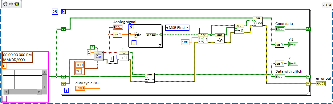
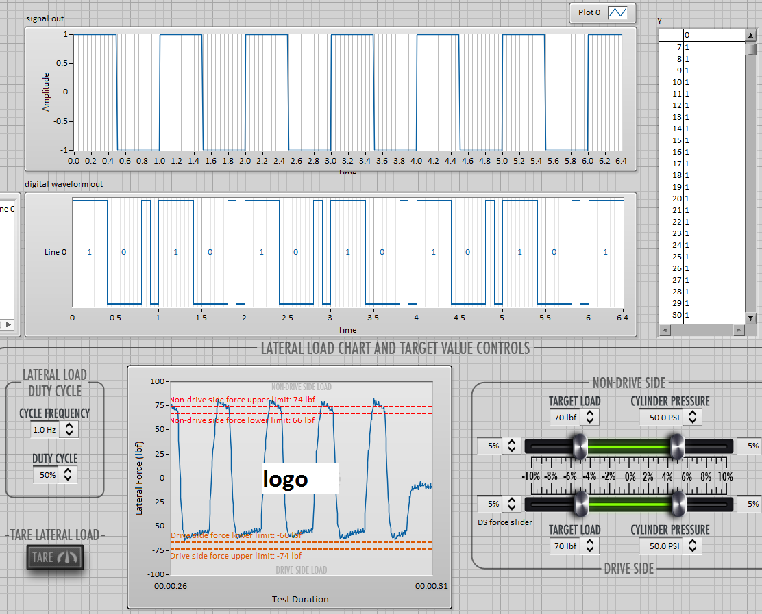
I try to use a square wave converted to digital output to operate some solenoids but seeing some problems with the cycle on the digital waveforms. The output frequency will always be of the order of 1 Hz and duty cycle must be adjustable to integer values. I have attached a simplified below, demonstration that shows the digital/analogue output VI I used initially. the problem with this VI, is that if I choose a cycle that is not a multiple integer of my samples for waveform I get seeds. If I use the Boolean digital VI table this problem disappears in my simplified code, but in my real program the problem reappears.
This image shows the waveform analog generated as well as the digital output that results.
In the digital waveforms, you can see that the duty cycle of 50% is sometimes applied during the single loop (~.2us) instead of more than 1 sec iteration, although the curve of actual load indicated in the table at the bottom seems to suggest that LV ignores this glitch (somehow). As I said, the problem disappears if the duty cycle is an integer multiple of the sample/loop. Timing of the loop is torn apart by other e/s to 2 000 Hz/400 samples per loop and 100 Hz/20 samples per loop (large enough VI otherwise I would include it). Obviously, I could change them to get 50% as a multiple, but this does not solve the problem if user needs to adjust from there.
Can someone point me in the right direction here? I'm sure that there is a stupid/easy solution, but I can't seem to get.
Thank you!
You might try turning the inputs A and B of waveform of the VI of the digital samples append. It seems that A should be the fate of the shift register data (the original data) and B should be added (the new waveform) data anyway, at least conceptually.
Paul P.
Engineering applications
-
Age of Empires 3 error 0003: could not compile the file 'aiLoaderStandard.xs '.
People,
I bought the version of digital download of age of Empire 3 full of steam for installation on my laptop Windows 7 Home Premium. Already, I have the CD versions of all games on my desk, but was also able to install it on my desktop in my Steam account.
In trying to play the AOE3 game on my laptop, I get the following error:
00:00:00 (0) xs: error 0003 could not compile the file 'aiLoaderStandard.xs '.
The net effect of this error is that when I run the game, the AI does nothing. He can place a hometown and a Explorer and/or civil, but they do nothing. I tried to uninstall and reinstall the game several times. I also applied all the patches I could find, to include the last being.
In addition, when you try to play the TAD version, I do not get the aiLoaderStandard.xs error, but it fails to load the map and never even begins.
Help, please!
Hello
You can view the proposal contained in the link, and check:
http://Forum.AgeCommunity.com/forums/thread/480165.aspxIf the problem persists, you can create a new thread in the forum for better support.
-
What is the HP Digital Imaging Monitor? Apply to my operating system, Windows 7?
What is the HP Digital Imaging Monitor? Apply to my operating system, Windows 7? I want to remove the icon from the task bar (toolbar in the lower right corner of the screen) that I never use it.
Picardjc wrote that "Digital imaging monitor is part of the HP software that communicates with your HP printer. This program allows to read the inklevels, get an out of paper message, scan from the device to the computer and so on. It is not necessary, but it will restrict the use of printers if you delete. "Understood. But for my printer HP Officejet Pro 8000 A809a, what is the purpose of having the digital imaging monitor icon in the taskbar Windows7 sp1 of the Notification area (aka system tray)? My A809a is NOT an all-in-one that includes a scanner; It is simply a very good printer. When I start to print something, if you need ink or paper, that information is displayed on the screen of my computer. So I ask again: why is the icon of monitor digital imaging on the taskbar? I clicked on at the time of this icon (I not print anything, but as usual, the printer is turned on), and nothing happened. R.N. (Roger) Folsom _ P.S. below I'll post some other discussions (with links to their locations) of the digital imaging monitor, I discovered before finding this site on which I am writing. There are a variety of opinions on what makes the digital imaging monitor. HP Digital Imaging Monitor is for HP director system tray access. This is necessary if you want to use the buttons of all-in-one on a HP printer all in one to scan documents or transfer photos from a camera manually. Closing the icon monitor HP digital imaging in the Windows system tray can cause the HP all-in-one to lose part of its scanning features and not the connection error message. In this case, you can restore all functionality by restarting the computer or by starting the HP digital imaging monitor. SOURCE: Yahoo http://answers.yahoo.com/question/index?qid=20080115093754AAlajpq - Re: REMOVE HP Digital Imaging Monitor of Systray? [Edited] 03/08/2011 14:05 - edited? 03/08/2011 14:08 Yes, it is safe to remove. In my view, it is usually in the program group under start / all programs / startup. Simply navigate under the Start button, right-click on it and delete! If it is not there, then remove it from the registry: run regedit and go to HKEY_LOCAL_MACHINE\SOFTWARE\Microsoft\Windows\CurrentVersion\Run and delete it from the list in the right pane. If she is not there, then try hkey_current_user\\software\\microsoft\\windows\\currentversion\\run it's better than using msconfig and uncheck it. In my opinion, msconfig must always be set to Normal startup. Your printer will always print without that annoying obstructive utility called Digital Imaging Monitor. Ciao! Casey Henderson, MCP SOURCE: http://h30434.www3.hp.com/t5/Web-Printing-Software/REMOVING-HP-Digital-Imaging-Monitor-from-Systray/td-p/253515
-
Toshiba Journ.e Touch is compatible with the Adobe Digital Editions software?
Greetings from Barcelona!
I have problems to allow my Toshiba Journ.e Touch. Adobe Digital Editions recognizes the device, but there is no way to allow it, there is no option for this.
So I can't transfer my ebooks from my computer for the Toshiba. When the Adobe Forum, it seems that other users had the same problem. I can't transfer my ebooks from my computer to the Toshiba device.
Anyone know what the problem is or how to fix this?
Thank you very much!
Cristina
Hello cristinadeseras,
Unfortunately, it is not possible to use the "Adobe Digital Editions" on the JournE Touch.
The requirements of the JournE Touch is not for this program.
Best regards
-
Cannot send the Dolby Digital XP on Satellite P100-347
The problem I have is that I can't get the Dolby Digital to send from my laptop to my amp, apart from the use of the library. I have the portable (Tosh P100-347) connected to my amp via a SPDIF cable.
Basically, in Media Center, I am able to change the settings, so that the amp captures the Dolby Digital signal, during playback of a DVD from the laptop, however, I am unable to get this transmitted signal during playback (HDTV) videos that are stored on my laptop. I know they are encoded with dolby digital.
Also, if I use another player media, such as media player and media player classic, I'm not able to get the signal digital dolby conveyed either.
I took a quick glance and think I have changed what is necessary, but still can't find anyway to do. I would get this sort you like playing HDTV content from my laptop and also play the latest games in dolby digital when available.
Help, please.
Hello
Check please the sound properties in particular speakers and under Advanced settings, select speakers 5.1 surround sound.
I hope this will be help!
-
Why my sample rate does not match the output of timestamps in the waveform?
Hello
I run a simple application to read the data of two pressure sensors output signals 0 - 5V to a NI9215 module, and one connected to the 9237 module load cell. They are housed in the 9172 chassis.
I am new to DAQ and labview, and I find it difficult to reconcile the sampling frequency that I put in the sample clock and the apparent rate data (according to the timestamps in the waveform that I output to a text file). For example, if I ask 100 Hz rate (and 10 samples to read), the data appear to sample at 1612,9 Hz. If I ask the sampling frequency of 1000 Hz, outgoing data is 1612,9 Hz to 20 kHz, the data came out to 25 kHz.
Can someone tell me to trust the timestamps given in the waveform that is written in the text file, and if there is a way to check this? If this timestamp is correct, how can I force the application of sample data at the requested speed?
As a secondary issue, in my attached VI, you can see that I have an attached to an array of construction shift register. I can't understand how to initialize the array outside of the loop as it clears the table before the next time I run the program. Any advice?
My VI is attached.
Thank you
Claire.
Hi Marc, thanks for the quick response and the right explanation. It's all much more clear now.
Have a great weekend,
Claire.
-
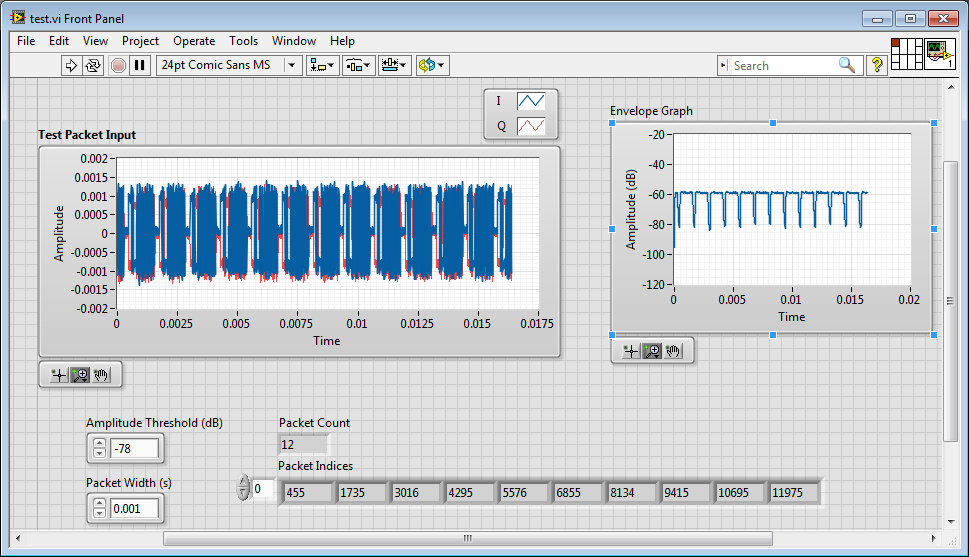
How to extract the signal from the waveform of my power level designated?
Hi all
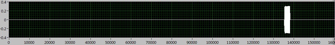
How can I extract the signal of the waveform accroding to the power level? I read the Trigger & Gate .vi, but this vi retrieves the signal duration. I want to extract the signal depending on the power level.
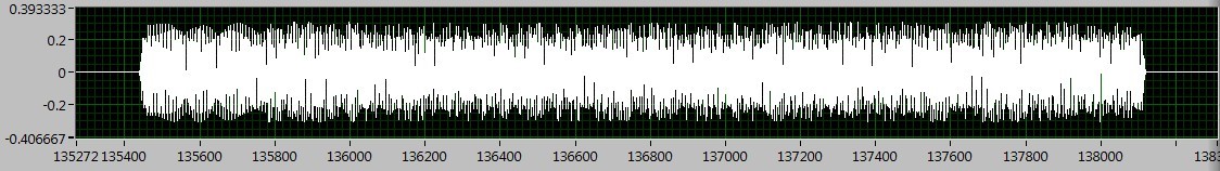
As shown in the following figures, the signal I want to deal with is between 130000 to 140000, if I Zoom, I can see the useful signal is between 135400 to 138200. The question is how to extract the signal in the area?
I tried the sub_NoiseEst_And_Chop_Shell.vi in the example of Packet_based_link also, but this Subvi seems to be a bit slow. Can someone give me the best advice? Thanks in advance!
I'm working on something similar, but have not had time to fully develop.
My idea was to use an envelope detector (low pass filter) and then use a detection of energy VI on the envelope.
Here is where I left
-
FPGA connect for compiling the server
Hi all
I'm just trying to write my code for my Spartan 3 FPGA. I was moved to another computer so I tried to install the right tools... LabView 2010, the module, LabView FPGA 2010 so that the pilot of the Commission of the Spartan Xlinix I use. Windows XP (32 bit)
Everything seems functional until the moment when I try to compile the code on my device. Apparently it "impossible to connect to the build server" or "compilation tools are not installed on this computer." I thought that all that is necessary to compile is included in the download of the module.
Is there some piece of obivous I'm missing? Thanks in advance.
Hi Oli,
I had the same problem recently. It is very important that all the good software and drivers are installed in the order so that everything works as expected. Looks like you have installed the driver appropriate for the Xilinx Board, you may not have Compilation of Xilinx tools for your FPGA. For the Spartan 3 FPGA, I recommend that you download Xilinx tools 12.4. This will allow your computer to compile the FPGA bitfiles for your specific FPGA module.
Kind regards
-
Updated reading (waverunner 6100) scope of the waveforms?
I use an oscilloscope (LeCroy) waverunner 6100 and able to get the waveforms of the via drivers downloaded from NI.com. But I would get a waveform only when a new acquisition happens (not not to read the same waveform all the time). How can I do? There is a "read only waveform.vi" available on the site, but it does not work with AUTO trigger mode (I think). I am currently reading in waveforms while loop with "Fetch waveform.vi", but I'm not sure that it reads as "refreshed" display... Here I read some registers (whatever) status or there is already an existing solution?
Hello Alex Harley,
Alan LeCroy Tech Support here. The waveform read various screw run the command 'Arms', so it is not for use in Normal or automatic trigger mode. We recommend that you use this command, because it uses the unique relaxation mode, which is the mode to use when you want your program to control when the scope triggers and so make sure that you're reading data retrospectives that corresponds to a specific triggering event.
If you prefer to run in automatic mode or Normal mode, you must use the VI 'Wait to acquire full' which is located in
the range of data/Low Level function. The looks for the registry "INR" testify to a new acquisition.Best regards
Alan
-
How display the waveform acquired DAQ card separately in wavefrom graphic
I NI 9239 DAQ card and it has four channels. I need to create a user interface graphic labview in which I need to display all the forms of four wave separately. If I select all four channels of the daq assistant and connect the waveform table all four waves are coming to overlap... I need separately for the treatment... what should I do?
Thank you and best regards...
Try this
-
DAQmx Read simultaneous calls on the same digital line
Hi all
I use v10.0 LV 32-bit on Windows 7.
I use DAQmx Read (in a task) to check the value of a digital line. Is it OK to do this in two different locations in a program at the same time for the same digital line? Or I have to put a wrapper around reading to force operations to be sequential?
Thank you
ZolaWhen you need to expose the capabilities of resources to multiple areas within a project (expand the scope of a resource) it is common to wrap the resource in an Action engine to encapsulate the resource functions. See here for an example of a 'Module on resources' material and a discussion animated about how this code help development construction and avoid resource conflicts. If you have not read famous nugget again – he of Ben is a link in my tag "Required_Reading".
Or more directly. Yes, you should encapsulate these readings DAQ to avoid suspended
-
missing samples in the waveform graph
Hello world
When processing a file .wav into pieces, I noticed that there are missing samples on the waveform graph where two pieces must be met for the display. What could be the cause of this? Any help appreciated. Thank you!
Milan
Your method of reading in pieces in a for loop is create a table 1 d of waveforms with the tunnels of automatic indexation. It is as well as what you have the data appear in different plots. I don't know if that's what you want.
But if this is the case, the problem is that you get to the last point of the first plot, and the first point of the next parcel is a different value. Because they are two different plots that you do not get the line to join them, as you do between points that are part of the same plot.
-
Convert the waveform (DBL) to a cluster of 2 elements
Hello
Can someone help me to convert the data type of waveform (DBL) to a cluster of 2 elements (X, Y). I found a few examples online, but I get an error when I wire everything together. I use VI of Tektronix to acquire a signal of channel 2 of my noculars, which I am able to do, but now I want to convert this data to a cluster so that I can use it for an existing application to acquisition. I have attached my VI version 8.2.
1Thanks
The is easy since it is part of the waveform data type. The X, you will need to calculate based on the dt by using a loop FOR.

Maybe you are looking for
-
IiPhone 5 c. Clock freezes when the phone is locked. When unlocked clock restarts as soon as the phone is automatically locked, locked switched off etc. It then keeps time (although still wrong) until this that locked again. Tried another Sim Card. T
-
Re: Satellite A200 - lights ever time!
My TOSHIBA Satellite A200 doesn't want to turn on every time sometimes it round after 10 attempts the blue icon Satellite lights every time.Any idea what's wrong with it?
-
Original title: Windows Server I don't know where to put this question, so here goes I am looking for a picture compatible Windows Server 2003 vmware study the operating system. Anyone know where I can find an image file?
-
Phone calls from Microsoft technical team
I had phone calls from the "team microsoft technical" eager to help with my computer as it is slow. they take me in "teamviewer" which I didn't like. are these people for real?
-
Widgets disappear randomly on wake on Z5.
All the widgets all suddenly disappeared when unlocking the phone randomly? This happened to me twice know about my Z5.