Connection Modbus
Hello
I am a beginner Labview and am looking for the solution pour dialogue with equipment (transmitter SCAIME measuring weight) in Modbus Protocol with a not variable between 2 interrogations and record responses in a file.
Frame problemas en of I know the Hexa format pour mark and the response of the transmitter, en revancheje don't know what VI nimodbus UTI.
Thank you in advance for your help.
A +.
Please try to post in English here
Translation
I'm from Labview and I'm looking for the solution to interact with the material (transmitter measurement weight SCAIME) in Modbus Protocol with a not variable between 2 questions and record the answers in a file.
I know that the image format to hexadecimal for the request and the response of the transmitter in revancheje don't know don't no how to use nimodbus VI.
Tags: NI Software
Similar Questions
-
How can I change the address Modbus to Modbus IO server programmatically?
Hi experts,
I use a cRIO 9076 that is configured as a server IO slave Modbus to Modbus TCP communication. I have always used the same Modbus address to configure the server of e/s and it has never been necessary to change so far. So I was wondering if there is a way to change address Modbus IO server programmatically, after it has been initially configured?
Thank you
Volker
Hi Volker,
There is an Express VI, that lets you create or change existing servers of e/s Modbus programmatically createand configure the Server IO. Once you set up like Modbus, you will be able to provide the address programmatically.
In regards to the address - you are right in that the Modbus address configured in the configuration of the server is not really used with Modbus Ethernet. According to Modbus specifications, the address is used when a network connecting Modbus Ethernet to a secondary network series Modbus via a bridge or a bridge. The specs say that the address 0xFF should be used on an Ethernet network. For more information on this topic, Please see page 23.
Hope that helps!
Best regards
-
Hello Forums or
This is my first post on this forum and I've been using labview for about 8 months now
I have a problem about writing data in the modbus registers through a server of e/s defined as a slave modbus for my hardware 9074. Once I finished the project of construction and deployment of the variables and by following the instructions here , he reports no results but a row of zeros. I have the DSM nor opened and configuration modbus master to see whether the data is actually read or written on the respective sides that give the same line of zeros so. What I am actually trying to write is a single-precision floating data table. The registers are structured F40000-F46534 runs from 10 items or have them for range AF40001L1-AF46534L1 of the AF40001L10 point where it's an array of length 10. (Referenced beaches here)
I know 1 thing for you, the modbus connection works and is ready for data requests, I tested cela NI DSM and set manually the data for and received my master.
System and project specifications
Windows 7 operating system
LabVIEW edition development system complete 2011
No module Labview DSC, but I use the real time such referenced by one of the documents
This project is an application in real time with fpga mode (and not scan interface)
The master and the slave are the same network and subnet
Connection Modbus type: TCP
9074 compact slots rio 8
9234 module x 3
module 9221 x 1
9472 module x 1
Engine service Variable shared running on windows os and rtos system
Used this guide to learn more about the Protocol modbus, as I have searched all over the internet to learn more about modbus
I already have software Modbus IO Server installed on the crio thanks to max or 1.8 for NI RIO 4.0 version
file attachment (s)
Image of software specifications Crio
Image of data written in scheme-block rt variable
Short version of the problem: why is the e/s no variable writes in with the converted correctly data?
Okay, Yes, it's that I was the one proposed. Regarding the news of the error, if you look at the bottom of your image to DSM, you see a little commfail and an error code, but it seems that those are OK.
The only thing I can think is that DSM (or another function) is written for a range of values that includes 400004. I suggest you to put into service 4-going to a range of 3. 3 s are entered only (perspective control), then you can be sure that the master is not trampling on the data. Once you have checked that, look at DSM and any other code running to make sure q EU not accidentally write 0s to the same reg.
-
How to connect Labview to PLC Modicon Quantum (140 CPU 311 10) with Modbus
I was wondering if someone could give some tips on how to connect Labview to Modicon Quantum plc (the card is 140 CPU 10 311). I am eager to serve a Labview HMI to control the controller that is used to implement the control PID with a VFD. Currently I can communicate via Modbus to the API for programming using UnityPro XL, but I have no idea how to connect Labview. I read the article on place OR "connect Labview to any PLC via Modbus", but I don't know yet. Any help will be greatly appreciated.
Hey Greener.
Communicate with the PLC via Modbus usually requires the Datalogging and Supervisory Control (DSC) Module to have this feature available in LabVIEW. The white paper which indicated you using this module, which may explain why you can't get the communication at work. If this is something you don't have, and purchasing a license is not an option, then you might be able to use Modbus unofficial libraries to get the functionality you need. I have included a link below to a Modbus for LabVIEW library that you can try.
DSC module:
http://sine.NI.com/NIPs/CDs/view/p/lang/en/NID/209851
Modbus Library:
http://www.NI.com/example/29756/en/
Kind regards
Ryan
-
LabVIEW Modbus TCP with VFD. Could not establish connection / error 56? Any thoughts?
Hello
I'm trying to establish a connection to a VFD (Variable frequency drive) for academic research, for testing purposes. My implementation consists of:
---> LabVIEW (Master)
---> ABB ACS880 VFD (slave) with adapter from Fieldbus FENA-01
---> (ABB motor induction)
---> (Internal Combustion Engine)
First of all, I'm new to Modbus TCP protocol, but I went through all the white papers of NOR, I have read and followed all the instructions from the manual of the VFD and the fieldbus FENA-01 adapter manual. I'm also pretty new to LabVIEW, but I'm confident, I have the knowledge to create the necessary VI.
I created a simple VI who would be able to read some registers the VFD, which is attached below. The VFD is connected by Ethernet to network local ethernet and the Master PC is connected to the same network. When I run the VI, 56 error, which as I read from other messages of the forum is to not get answer within the given time.
I tried the things:
--> Check all cables are connected properly
--> Double check the manuals
--> Checking the FENA-01 in the chassis, which gives the indication of waiting for query modbus
--> Looking for a gateway IP address, but I did not find, so I expected, I don't have to add it to the VFD parameters
--> FENA-01 refreshing settings that always translates to "offline" status
-->, I also checked in Labview > tools > Options where you check TCP/IP and there no port 502 written but I do not change it cause I had to leave the laboratory at the time. The port number was something like 3363 (something like that again)
Issues related to the:
--> Do I need to specify a new device somewhere in LabVIEW or in the control panel?
--> What I need to create a separate VI to make the connection?
--> What 'send 1150 for operating loan' and ' send 1151 for operation "means the control word?
I would be very grateful if someone had information about this before the end of the week. I'm running tight on my period and I just can't stand this VFD with the limited power of the local command of monitoring mode.
Thanks in advance for any help.
Neo
Hello, the problem is solved, and this could be a solution to problems like these.
The IP address of the car was not on the same network as the Local Ethernet network connected to it. The IP address of the disk was 192.168.0.16 and the network was on 192.168.1.1. Once the IP address of the network changed to 192.168.0.1 communicated properly.
I also have ping after and showed the communication.
Thanks for the reply TST.
Peace,
Neo
-
Hi all
I'm new in the world of labview and trying to build a VI that sends commands to a controller of the WAGO 750-881 at regular intervals of 10 ms.
To set each of the WAGO comics at the same time, I try so to send the Modbus fc15 command every 10ms using Labview standard TCP write module.
When I run the VI it works for about a minute before receiving an error message 56 telling me the TCP connection has expired. This strange thought, I decided to record the number of bytes sent via the TCP connection while running the program. In doing so, I noticed that the link broken after exactly 113655 bytes of data have been sent each time.
Thinking can I have sent too many messages, I increased the delay of the loop of 10ms to 20, 100 and 200 ms, but the error remained. I also tried to play with the TCP connection timeout and the writing TCP timeout, but none of these had no effect on the problem.
I do not see why this error occurs, such as the program works perfectly up until what brand 113655 bytes.
I've attached a screenshot of the base VI (simply showing a MODBUS command sent every second) and a more advanced VI (where I am able to control each of the WAGO manually by setting a frequency at which the DO is to switch between ON and OFF).
If anyone has any ideas on where the problems lie, or that I could do to debug more program this would be greatly appreciated.
AvdLinden wrote:
Hi ThiCop,
Yes, the error occurs after exactly 113655 bytes each time. Time-out control, I would like to use is 10ms, but even that will rise to 1 s or 10s does not error, which leads me to believe that's not the issue (as well, do not add any delay in the while loop, so let it run at the maximum speed showed that the TCP connection is able to send all the bytes 113655 in less than 3 seconds again directed towards control of time-out) is is not the issue here).
I tried the suggestion of Marco but having difficulty to translate the string returned in a readable string (rightnow the answer given is "-# +" ' ").
As for your second suggestion, I've implemented something similar, where I created a sub VI to establish a TCP connection, send a message and then close the connection. I have now to build each message and then send the string to the Subvi, which sends the command to my application successfully. While not the most elegant method to solve the problem, it solves the problem of time-out, which means that I am able to send as many orders as I want. So in this sense, the problem has been resolved.
If you have advice on how to properly read the TCP read the output, I want however to see if I could not get my first program to work because it is slightly more robust in terms of timing.
MODBUS RTU TCP is a binary protocol, as you show in your base VI, where you put in the form the data stream using byte values. So you have to interpret the returned answer accordingly with the Modbus RTU spec in the hand. Now what is probably happening is that the connection is suspended after a while because you do NOT read data from the device sends as response to your commands. The TCP/IP stack cushions these bytes and at certain point of overflow internal buffers and the connection is blocked by the battery. So to add playback of TCP in strategic locations (usually after each entry) is the right solution for this. Is there a reason any that you do not use the PROVIDED Modbus TCP library?
-
Hello
I have a compact rio, which has a 4 way frame this chassis is the three modules of ni9234, they are related using FPGAs for application in real time, then using shared variables in the low-speed loop associated with a slave modbus to communicate with the domain controllers, the nor 9234 accelerometers linked to them with option ac coupled iepe on c modules , my problem is the real-time application seems to work well even when power loss occurs it restarts without problem and the fpga written hard disk portable bin files very well, but without an accelerometer connected I get readings of low noise as soon as I connect an accelerometer to one of the outputs 10 it just goes to a fixed number (0.03125) as soon as you unplug it again He returned to readout noise, I ran a scan on the modules and get only a spike when I connect or disconnect the accelerometer, I tested voltage at the pins on the module and I get 22 volts CC which makes it more likely that the material is not the problem, but software is perhaps the cause to hang up, I join the project and files for your perusal. I also realized a new project which, in mode directly linked scan has the module entry in the shared variable and the scenerio even once again. Help would be appretiated.
Thank you very much
Jason
Whren using waveform with the 9234 acquisition, we recommend the following FPGA and RT model.
http://sine.NI.com/NIPs/CDs/view/p/lang/en/NID/209114
It can be extended as a datalogger with:
http://zone.NI.com/DevZone/CDA/EPD/p/ID/6388
or using shared variables combined with the analytical engine
http://zone.NI.com/DevZone/CDA/tut/p/ID/9851
The FPGA in all this, as well as the framework of RT have used successfully by 1000s of users. I recommend giving these a try.
-
Modbus/TCP connection to the controller of power Eurotherm EPack
There are examples of how to connect to a power controller Eurotherm EPack a modbus/TCP connection?
I downloaded the Modbus LabVIEW ni_lib_modbus_library library - 1.1.3.32.vip and installed using VIPM.
However, I am not familiar with the Protocol modbus and terminology such as coils, keeping records.
I can't even properly run examples for Modbus master and slave to this library :-(
Most important for me now is just to read the value of the artwork process.
"ITools" Eurotherm controller software provides information about something I think are an address of memory the value of process I want to read.
However, I have no idea how to set the various parameters to get successfully connect and read the value of the process.
Trying to solve my problem, I managed to have basic communication and engineering data conversion.
Now I can read values of process as the power line frequency, voltage and others.
Once you know, it's very simple (once you have the modbus library)

Some things that remain unclear:
-What values are 32-bit and 16-bit?
-is the method of addressing identical for all parameters?
-is it the same for reading and writing?
I would like to be able to write the target value, for example.
I'll contact the seller for these outstanding issues. The manual is not really clear (at least not for me). He mentions that some values may be treated differenly (they 16bits, but globally, so 5001 with a scale factor of 100 means actually 50.01 for example).
See the attachment for reading cover base.
-
Connect with the gas on TCP/IP Analyzer
Overview: I am trying to contact several Thermoscientific via TCP/IP gas analyzers. I have successfully set up the MAX connections and think I'm pretty close to being able to connect these data in real time.
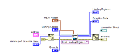
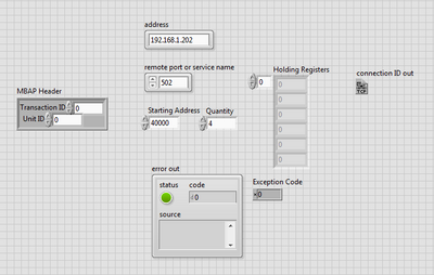
Questions: I'm not very familiar with TCP/IP or Modbus and clearly am not quite understand the documentation. I can succesfully open the TCP connection and do not benefit from an error. My problem lies in the plug correctly good values to the vi MB Ethernet Master query reading record keeping. If someone could help, it would be fantastic.
What I have so far:
I don't get any errors, but I don't read all the operations to be registered. I use a Trace level SO2 43i model ThermoScientific Analyzer. According to the manual, I am interested in register numbers are 40001 and 40002.
I have attached the vi. Any help would be greatly appreciated.
I have a solution! It turns out that the ID of the unit must be the same as the numeric part of the model number for a specific parser. She does not mention this anywhere in the documentation (at least, not that I could find). I posted my solution (vi) in case someone else wants to use them or to see what I did to solve problems. Thanks for the help!
-
invertek modbus communication by car
Hi all
Seems modbus is a way to communicate with the disks for a long time. For me, and because we have a new machine equipped invertel drive P2 is new.
So, after many emails between invertek I couldn't so much as to communicate with the reader with their software. Only her entry to go to modbus.org
For their software, I use a converter usb rs485 and I use pins 4 and 5 (pc connection), but for modbus change for 7 and 8 (modbus)
Join is the manual for modbus for the driver.
My question is, what is the easiest to read VI (for now) of records and the way to the entrance. I need to input 03 (for reading), then the registration number?
Please help for the first step, then I'll build the complete software (I have now installed modbus library)
Thanks in advance
cpalka
-
Control data DATAKOM DKM 409 RS485 modbus output
Hello world
My project is to control a furnace and im using DATAKOM DKM 409 with rs485 modbus output. in this project, I want to monitor data using labview. reason to do this, I use a RS 485 to RS 232 converter but when I connect them to each other and to my pc there is no recognition of the machine and when I want to use visa in BT it cant recohnie any device connected to it and gives me below error:
LabVIEW: (Hex 0xBFFF009E) VISA or a library of code required by VISA impossible situated loaded. This is usually due to a required driver is not installed on the system.
my converter is under this link:
http://www.securitycamera2000.com/products/CCTV-RS232-to-RS485-PTZ-converter-for-DVR.html
Please give me a guide about what is not going in my project. I really don't know why I can't config my port of visa and my source of visa is not recognized
thnks
ERFAN Shahsavari
Hello my dear all
Here is the answer and the consequence of my work:
1. in the manual of my legacy notes that we can choose 1 to 253 device id and I chose 240 but it was a mistake and I have the device between 1 32 ID value. (If I want to select more than 32 a Repeater must be used)
2. According to the operating instructions register addresses are between 40001: 40095 example 40068 and because of the structure of MODBUS RTD (device id, the function code, address of departure, number of registers to read registry, control CRC) I need to set the register addresses 40068, but it was a mistake and it was bad. The correct registry address is 68 no 40068. And in the structure MODBUS should I use 68 no 40068 or using the modbus library, that I must use 68 as registry address 40068 not.
Thanks for your guides
-
Connect LabVIEW to Schneider Electric M258 Logic Controller (TM258LF42DT4L) error - 1967353901
I was wondering if someone has never connected this particular PLC before LabVIEW. I'm trying to control instruments connected to this API. These instruments aren't NEITHER, therefore they that I could not directly connected to the device via USB, GPIB or VISA. Whenever I have try t connect following this tutorial OR (http://www.ni.com/tutorial/13911/en/), I have an error message to my shared variable.
The possible reasons: LabVIEW DSC: (Hex 0X8ABC8FD3) the I/O modbus server cannot connect to the Modbus Ethernet slave device. Make sure that the slave Modbus Ethernet device working properly and that the connection between the master devices and Modbus slave is configured correctly.
Any help on this approach or suggestion for others would be greatly appreciated.
NOTE: This controller communicates with the CPU I use via a RS485 / RS232 serial port.
SAM
Right, but if the unit will not pass a review of the communication of its native software so it is not really a chance that LabVIEW will be able to communicate with him. I could contact Schneider and see if they can help you make contact with their software, we can worry about communicate using LabVIEW.
-
Power Meter Modbus rs485 via 9871
Hello
I'm under Labview 2015
I'm currently trying to connect has the place D Pm820 (meter) NI 9871 module in a crio 9076. The project is supposed to read the performance data in the registers of the meter (current, voltage, etc.) using the port rs485 on the back of the meter.
The pm820 has a pinout for rs485 2-wire with 1 (-) 2 (+) and a 3rd Armor/ground wire. The pm820 meter is a slave device that has several different protocols that it can run on (Modbus RTU/ACII8/7 and JBUS).
The setting of the counter are:
Protocol: Modbus RTU
Address: 1
Baud rate: 9600
Parity: None
I use the module 9871 for device communication for the cRio
I use the power cord that came with the module 9871 RJ50 to db9 and have the pins 4 and 8 rider (TXD + TXD +), and then connected to the (+) 5 and 9 meter jumper pins (-RXD, TXD) - and then wired to the (-) meter and ground on pin 1. I have read, it's how wire you the db9 connection rs485 2-wire.
My first goal is just to get the communication with the power meter so that the value that I see in the registry, it is what I should see.
I started using an example VI for holding registers (master modbus on target RT) reading as labview was pre-constructed and changed it so that its contribution would be to port 1 on the 9871 as created controls for my run configuration. Other I left the rest of the VI that it has been opened.
When I run the VI I see numbers appear in the registry list, but they have nothing to do with the power meter. I unplugged the power meter and still got the same result however if you unplug the cable connection the 9871 1 VI will be a mistake (as expected). I have the feeling that the labview speaks to itself through the 9871, but I'm not sure. I looked at other posts, trying to find a solution and came across a mention of having to set the thread mode, but I can't find a way to do it using the modbus library. However I could not find an example reading VISA registers the using visa I see there is a way to do it.
I enclose a picture of my VI and the front panel to show what I mean.
If I could help either make my VI work or at least get pointed in the right direction that would be great. I'm not against the use of the Visa library either. Also if you have examples or resources that would allow that they would be greatly appreciated
It's just a part of my project but just get work communication is my main priority at the moment.
Thanks in advance,
Mike
-
Exstance no of Modbus communication
I work with a rs232 for connection rs485 via a UNO2019 PC box. The RS-485 connection is going to be MODbus RTU, has about 4 slaves on the bus (MMI flowmeter, VFD, two temperature RTD). All theses devices are configured accordingin
9600 baud, odd parity, no flow control. the VISA resource would be COM3.
Now all of these components I worked with every day for numerious months. and VI implementation exists (almost) without error. I get an error code for the additional bytes to the port, but he spends the whole upward. I don't know if I'm not or write, but it has happened in every piece of software, I developed in labview (it does not check the boolean error so I guess that's not important).
Currently, when I try to read the registers of the MODbus slave, I get error:
-107380733 (that mean 100 different things that I have done my research properly, bad bytes to the port, do not use correct end characters in your message). But every time I have seen that error code discussed in question direct USB/RS232, not RS232 to RS485.
The attached string was
3-> MD series Master Query.vi
2-> MB series Master query Holding Register.vi
1-> address Test.vi
Thank you for any light you can contribute on my problem.
Problem has been resolved. It was a hardware problem as I thought. Apperently this code error will exist when your RS-232/485 is hard set via dipswitches do not send data.
-
Point of Modbus DSC read does not correctly
I use 2013 LV 32-bit on W7 64-bit. I talk to an industrial controller with Modbus to Ethernet. My current software uses the interface modbus DSC, in which I define the bus Modbus itself within a library in the project, and then set each point Modbus as an address within this definition of modbus. Inside LabVIEW, you can then get the data Modbus via shared Variables. I am currently using the dynamic variable calls shared, rather than static variables shared. I have points that are Boolean (coils) and real, with a read-only and a read/write. In general, it all works.
However, there is a real read/write that acts funny. If I put a new value, or the industrial controller assigns a new value, the industrial controller Gets the new value. Variable motor shared on my computer gets even the new value, as can be verified by opening the Distributed System Manager. But LabVIEW continues to read the old value, without error. Other points of read/write work very well, and I have looked on the definition of the address several times and cannot find any reason why this should be different than the others.
Does anyone have any ideas why DSM sees a new value of a shared variable, without LabVIEW continues to get the old value? I watched the init for the dynamics of SV case, and I see all the options I can change to try to solve this problem. My next attempt will be to rewrite the entire auxiliary system so that it uses the most recent Modbus Library of NOR and ignores the whole thing of DSC. It will be probably much better for other reasons as well. I noticed that with DSC and the shared Variables, the first time that the program runs it starts fairly quickly, but subsequent executions can take up to two minutes to connect to the SV.
Thank you
DaveT
Never mind. I think I found the problem. A bug minor configuration in my own code...
Maybe you are looking for
-
How to get rid of the text in the bookmarks bar? Reset default will not work
my bookmarks bar has changed. I clicked on default reset so just to see the icons, but it won't work. cannot get rid of the text.
-
PALM TX - Factory Reset question - need help
I have a PALM TX. The green power button on top seems the PALM TX turns on but not turn off the power. The home on the PALM TX button will literally reset the PALM TX by it turn off and save as a PC. The soft reset by clicking on the reset at the bac
-
Pavilion dv6-3120us Windows 8.1 plus his robot
Hello I have a HP Pavilion dv6-3120 us portable and, when installing Windows 8.1, I have constant audio problems. Every time I play something on iTunes, Windows Media Player or Youtube and I have access to any Web site, sounds becomes slowed down and
-
Lack of exit Realtek Audio in Device Manager
Recently, I noticed that my laptop no longer plays sound through speakers or headphones. The icon indicates that there is "no speakers or headphones connected. I checked the sound settings, and Realtek audio output (I don't remember the exact name of
-
How to log in as administrator in Windows 7?
I am trying to run Spybot which I just downloaded. However, after analysis I have not permission to solve problems because I am not the administrator. I checked my user profile and it shows that I AM the administrator. So I go in the folder accessori