Constant voltage using myDAQ output
Im a student and I'm using myDAQ for my final project, I have buil year VI and I want to add a constant output of 3, 3V, during the course of the VI.
searched the forum, impossible to find something with myDAQ.
Here's my VI:
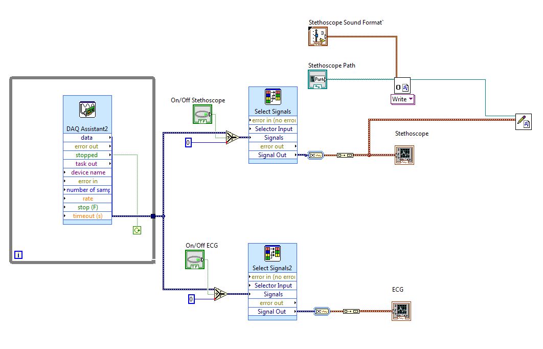
Just put a new assistant on the diagram of block and instead of the acquisition, select build from the beginning. Choose your channel. Select 1 sample. Wire your constant Assistant.
Tags: NI Software
Similar Questions
-
Using the output with 6009 or 6216 possible buffer?
Hello
I have a USB6009 and a USB6216. I need to generate a signal by using the analog output and I would use the output buffer. My questions are:
-The USB6009 has an output buffer? I always get an error, but I know from experience that this device is very limited, so I wonder if they have not only an output buffer... (Programs in input buffer are not a problem at all).
-J' took the USB6216 and I tried the example WfmGenUp.c downloaded from somewhere in the area of the developer (sorry I lost the link but fix the code) but I am not all analog output signals and after you press ENTER to stop the program (depending on the show) I get this error message:
NO MORTALS RUN - TIME ERROR: 'WfmGenUp.c', line 113, col 9, id thread 0x0000088C: DAQmxStopTask function: (is-200016 return value [0xfffcf2b0]). Measurements: On-board memory precision passing. Due to the limitations of system and/or the bandwidth of the bus, the driver could not write data to the device fast enough to track the rate of output of the device. Reduce your sampling rate, change the method of transfer of data (from interruptions on DMA), use a product with more on-board memory or reduce the number of programs that your computer runs simultaneously. Task name: _unnamedTask<0> Code of State:-200016
I don't know if the problem is just that the 6216 does not support the output buffering or the other...
-So, if the output control is not supported by 6009 or 6216 what would be the best way to constantly generate signals to 100 s/s?
Thank you very much
Kristel
Hi Ryan,
the USB-6009 case has 150 s/s softwaretimed AO, so you won´t be able to use AO stamped with the module.
The USB-6216 supported in the analog output buffer, just follow the recommendations that the driver gives you,
for example by reducing the sampling frequency, if there is an overflow memory due to the limitations of system and/or the bandwidth of the bus.
Experiment with the parameters and the basic to see in what range of sampling it works.
You can find appropriate examples
ANSI C:
C:\Dokumente und All Anwendungsdaten Users\Dokumente\National Instruments\NI - DAQ\Beispiele\DAQmx C\Analog Out\Generate Voltage\Cont Gen Volt Wfm - Int Clk ANSI
LabWindows CVI:
C:\Dokumente und Users\Dokumente\National Instruments\CVI\samples\DAQmx\Analog Out\Generate Voltage\Cont Gen Volt Wfm - Int Clk Anwendungsdaten All
-
Specify the end point for the digital using an output circular buffer
When you use DAQmx and a NOR-DAQ for issuance of a digital signal using a circular buffer (buffer Renault). The program works and works, but when the 'DAQmx Stop Task.vi' function is called to end the task, he stops at the output buffering as soon as it is called and does not wait until the buffer pointer reaches the final value in the buffer. I would like that the program to wait until the buffer pointer is on the last value in the buffer, does anyone know how to specify this setting?
If you need to stop on exactly the last sample output you will need a way to trigger the stop in the material. The options available to you will depend on what hardware DAQ, you use, but here are some possibilities on the top of my head:
1. set up a digital output redeclenchables task finished (not all hardware supports). Set up a counter of output to issue a periodic trigger with the necessary synchronization signal such that the end result is a "continuous" digital output without interruption. When you stop your loop, stop the task of counter - digital output ends his generation but the trigger signal will be removed and so it will not continue after that.
2. If you have an unused extra digital output line, add it to your task. This line should exit 0 all except the last sample. Physically, this additional digital line in a wire line PFI and use it to trigger a meter output. Have the output counter generate a single pulse of some long-term (long enough to ensure that the software can respond prematurely). Use the output from the task of counter as a trigger of break for the task of digital output. Do not start the task of the meter until you leave your loop. Do not stop the task of digital output until you have detected in the software that the meter has been triggered.
If you need to stop on approximately the last sample output, you could query the TotalSamplesPerChannelGenerated property after leaving your loop and only stop the task once it reaches a multiple of the size of your circular buffer. This is no guarantee that it stops on the last sample (if you use a device on a bus with a latency higher as USB or Ethernet the non-determinisme would be worse).
Best regards
-
control of DC motor using myDAQ
Hello
I'm building a DC motor using myDAQ command, that I ran into a couple of problem with the STOP button and the Max speed Min. For some reason, the diagram of waveform becomes crazy I will attach my file VI.
Description of the project:
-An engine-engine-OFF button
-A control for fast / slow
-A switch left / right
-A speed once button maximum (100)
-A speed once button minimum (10)
-An indicator of instantaneous speed (0 - stop, maximum 100)
-An indicator that signals the directionCould someone tell me why it happens and how to solve the problem?
Thank you very much!
Best,
Istrael
Hi Istrael,
You use a lot of CPU resources by not including not calendar in your loop. I think that your questions can be resolved if you place a timer 'Until the next ms Multiple' in your 'pulsegenerate.vi' in a loop. This will actually load on your CPU if you set it to 1 ms.
I hope this works,
Paul
-
I can measure analog USB supply voltage using Labview?
I'm basically feeding a (nominal) 5V USB power sensor, but the output of full scale depends on the real for a particular measure input voltage - what I want to do is to get labview to measure the voltage at the USB port at the same time it samples the voltage of the output sensor and then that of full scale output for that instant in time can be calculated and thus give a measure more accurate. Is this possible in labview? Thank you very much.
Haydn Barker
Makes a lot of sense, actually - probably would see a few mV dropped from the point of measurement of the sensor point... then you work with equations/remedies just to work with an inaccurate level anyway. Okay well I'll write that off as a bad idea then and just stick to the system, because it isn't now - I don't know that it will be enough. Thank you for your answers and help.
-
What is the best way to run two concurrent programs using the output of either executing the other?
I wanted to just kind of get a notice of some people here. I have two main screws the first is a data acquisition system that displays 99 different sensors and which feeds on these data in a table. The second is a real-time processing system that is designed to take the painting and do many calculations. The two output data from screw at the front that I want to see, so I don't want to use just as a Subvi.
Is there a simple way to run two screws, using the output of the data acquisition system to power the processor so that you can easily see the signs before two screws? I had thought to simply copy the code from the processor in real-time in the DAQ VI, but I fear that the VI resulting will be very large and unsightly.
On a side note, I'm more thinking about this? I apologize if this is a stupid question, it has been a long week... aaaand it's Wednesday.
Look at the Architecture of producer/consumer. It will be a good starting point, even if you find that you need to change. When performing data acquisition and processing of tasks in parallel loops, they can both run simultaneously. Both can feed data to the main draw of the VI.
I'd probably use three loops with the third being the user interface only. All that must be displayed to the user is sent to the GUI of the acquisition of data or processing loop loops and commands or entered by users are returned in these loops, probably through queues. The wall of the VI of data acquisition and processing VI are never displayed to the user. Especially the treatment, because it runs on a system in real-time, should avoid synchronization issues that can present a graphical interface.
Lynn
-
Counter trigger using the output of another counter
Hello
I want to configure my USB-6221 Panel in the next mode
1 Counter0: Generates impulses in continuous mode.
2 Counter1: Fires by the impulse of Counter0 (rising edge) and generates a train of 128 pulses with a certain frequency.
3 DigitalInput: Using the impulses generated by the meter read 128 digital input values
Cnt0: _____|______________|______________|______________|_________
Cnt1: ______|||||||||||| _________|||||||||||| _________|||||||||||| __________|||||||||||| ___
DigIn:___xxxxx___xxxxx___xxxxx___xxxxx___
The problem is: I can't seem to trigger the Cnt1 using the output of Cnt0.
If I connect using the Cnt0InternalOutput: I get the error: this connection is not supported by the Board of Directors
If I connect the trigger for a PFI (e.g. PFI5) I get the error: some resources used Cnt0 (I see no reason why by ok).
I tried for awhile to do in a different way (I completely mixed my vi) but I did not.
If anyone has any suggestions please shear them.
Thank you
Paul
Ignore my previous post.
A mistake is this sample clock: finished sample doesn't seem to work with shutter release in this configuration.
In any case, I found a way to get around and reach my final goal (the object) with a bath other counters and configuration of digital input.
-
Call stored procedures and using its output parameters in a report
Hello
I have a procedure defined in a package on the database. This procedure returns a number of output parameters. How to call this procedure and use the output parameters in my report?
Thank you, MarkDepends on the level at which the procedure should be called. If its at the State level, call the form in the trigger-REPORT-BEFORE (or AFTER-PARAMFORM) and store the off-values space reserved columns. These you can use anywhere in your report.
-
Sensor using IR Sharp 2Y0A21 to enter data in a labview program using mydaq
Hello
I'm working on a LabVIEW project. A portion of it (creating a sub - VI), I want to make use of a record international sensor (SHARP 2Y0A21), in order to measure the proximity of my hand from the sensor. I also have the myDAQ to help me with the sensor inputs. I want to make a program that turns a Boolean LED on when my hand is out of range of the sensor. Please guide me as to what I have to do to make it work. A few steps on how to make my program will be highly appreciated!
Thank you
Ksquared.
Hi KSquared,
This article by DeveloperZone, measure the Distance with myDAQ and Sharp IR proximity sensor should help you get started. Although the model of sensor used in this article is different, the specifications seem to be very similar suddenly look at the data sheet. If you follow this link, you should be able to acquire the output voltage of the sensor, filter and convert the voltage up to a distance. From there, the rest of your program should be fairly simple to complete. Feel free to post any other questions you may have about the article or your application. Hope you find the article useful!
-
False values of voltage using NI 9225 and ELectrical Power Suite 2014
Hi all
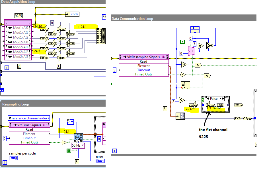
I have a few problems regarding the use of a map of analog voltage NI 9225 with code exaple quality Applications of power (cRIO) (Delta-Sigma) of the Electrical Power after 2014. Running the example code I values of voltage wrong, they are exactly doubled! For exaple with a 230 V RMS input I get 460 V RMS. I think the problem is the module, because by default, the code example expects to use a module NI 9242. Before the upgrade to LabView 2014, everything worked perfectly with EPS 2013. Am I something missung? I configured the C module in the project manager in the same way that I used with EPS 2013. Can someone help me? Thank you
Gianluca
Hi Gianluca,
If you use other types of modules in the example, you must take care of the conversion of accuracy in the FPGA VI.
As FPGA VI resampling takes the signal of type fixed point +-24.1, you convert the +-24,10 and-24,5 to 24.1 in the Data Acquisition loop before feeding to the FPGA VI resampling.
And in the loop of data Communication, you restore the output of +-32,3 to 32,12 - signal + and +-32.7. Notice at the time the zoom in and zoom out are equal.
If you change other types of modules of different precision, you must change the precision of the given thread.
For example, 9244 accuracy is +-24.11, so when you convert it to +-24.1, you must restore it by variation of-32,3 to-32,13.
Please refer to the screenshot:
-
generation of clock using mydaq
Hello world!
I just have a very BASIC question. I know that some of you may find it easy.
Again, I'm new in LabVIEW and I try to use a data acquisition equipment NOR myDAQ. In the application, that I'm doing, I need to get a pulse generating myDAQ signal and use it as input in my multiplexer. I searched for positions and I think that none were asking such a simple question.
If there is no solution for this, please link with me. Thank you very much!
Kind regards
Falsehope
FalseHope wrote:
I am afraid that I can not do. I'm only using the computer lab of the school and he removed the LabVIEW examples folder (perhaps to prevent students to access the examples during the reviews of practices). So yes... I am a student with limited access to LabVIEW.
But I talked to the it DEPARTMENT of our school and it allowed me to download the examples instead. However, I can't find the codes available.
Kind regards
Falsehope
IMHO, he is a stupid thing, a good teacher can create easily of exercises and tasks of review to "measure" the real knowledge of the students, even if they use the built-in LabVIEW examples. A school should help during the learning curve and not by disabling the examples incorporated, but giving creative tasks...
I've attached an example VI that will generate an output of 1 kHz by DIO-3 and DGND counter. (I tested with a myDAQ device, it works)
-
Precise triggering voltage input and output generation in the DAQ Assistant
Hello
I wonder if anyone has come across a simular problem with the synchronization of input and output voltage. I use a box 11 LabView and NI USB-6259. I have been using the DAQ Assistant to configure the input and output channel. In particular, my task is to generate a single rectangular "pulse" as the output voltage to drive a coil and once the pulse went to get a signal from a sensor of magnetic field and get a power spectrum. This means that the order and the time during which the DAQ Assistant is used is extremely important. For example, the output voltage channel must be opened first for 2 seconds. Subsequently, the channel of input voltage must be open for 1 second, in which the sensor signal is obtained and post-processed. Only after these tasks are performed in this order he can can be repeated in a loop until the experiment is over. I don't know how to trigger data acquisition assistants (one for entry) and the other for the voltage output correctly. Y at - it a trick?
See you soon
Michael
Hi Dave,.
Thank you that I wired the error strings but the timing issue was unrelated to it. In the DAQ assistant, I simply had to choose the continuous aquistion of the 'samples' methods 'N-switch' for input and output voltage and all works fine now.
Thanks again
Michael
-
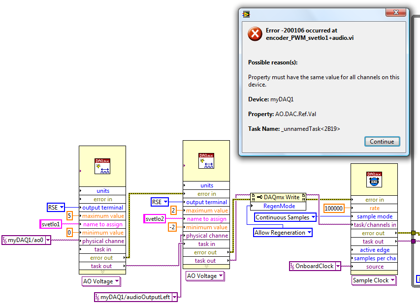
myDAQ - output multiple analog/audio
Hello
I try to use fully the potential of myDAQ - I like to use all 4 analog outputs at the same time, in a VI.
That is, 2 outputs analog (AO0 AO1) and 2 audio outputs (audioOutputLeft, audioOutputRight). Different values mini-maxi are also required, 0/5V and AO - 2/2V for audio.
I can run analog 2 or 2 audio outputs at the same time, but not all 4.
Simply add two separate DAQ help gives me error 50103 well known, add all channels in a single DAQ help error 200106 (due to different values of the min - max)
I also tested functions for data acquisition - create channels in the series, but who returns the same error 200106.
I don't need exact date, just of various waveforms on all 4 outputs would be great.
Is in any way how to proceed? Any help is an apprentice.
JakubHi Jakub,
According to the documentation of MyDAQ the following link http://www.ni.com/pdf/manuals/373060e.pdf
Page 6 it is stated the following:
-
what you get when the sequence is used as output, tension or strain?
Mr President
I m using scxi1520 with watchkeeping configuration, by setting the entry like strain, what value I get is not strain that I calculated analytically. someone told me that what value you get by that is tension not strain, I calculate strain from here by the formula.
I don't get that this is strain or tension.
I have an extensometer of 120 ohms with two gage factor. Please clear my doubt I have with this as soon as possible.
Think about the data being represented in different ways. Your contribution is the strain. The strain gauge that converts resistance. The bridge becomes the resistance a tension. An amplifier multiplies by a constant tension and perhaps subtracts an offset. The analog digital converter changes the analog voltage to a sequence of tension with two possible values (0 to 5 V) at every moment in the (digital) sequence. The computer processes these digital tensions as numbers that have a strong correlation with the amplitude of the analog voltage.
But you try to measure the deformation, so you don't really care voltage analog or digital, except that need to know the relationship between them and the original strain.
Your tension measures data acquisition system. You must provide conversion from units of the strain through calibration.
Lynn
-
Is it possible to play an audio file of labview (using myDAQ)?
Hi all
I use a myDAQ (first time). I'm reading an audio file at a certain point in my VI.
All of the examples I've seen use audio and then play on the audio output port. Is it not possible to simply find the location of the file and then play on the importation of audio output under conditions specified in the VI or even sound? I'm not trying to play large files or large amounts such as songs. I only want one his congratulation when the task is completed (2/3s).
Any help would be is appreciated (even to say this is not possible!)
See you soon
Why not just play a WAV file? Use play File.vi sound as shown here.
Maybe you are looking for
-
Satellite P200D Vista recovery disk will not work
The OS is screwed on this laptop and when I try to boot normally a blue screen flashes so fast that you can't read and it stops. I try boot in hosted HDD repair he said: "the installed program cannot start. Click OK to turn off the computer. The CD d
-
Siri free eyes cannot open iHeartRadio
I just got a new 2016 HR - V, and there siri eyes-free. When I hold the button while in the Park to say 'Open iHeartRadio' she tells me something since she can't because I'm driving. I have configured to start iHeartRadio playing while it is open, bu
-
3520 fails installation eprint
Hi all! I bought a Deskjet 3520, wanting to use google cloud print, I tried to activate ePrint. After having accepted the terms and said yes to the future updates, he started looking for updates, after a minute, while the display shown "Connection",
-
question of partition dividing Acer e1 - 572 g
Hello everyone I bought an acer e1 - 572 g with a 750HDD. My question is can I divide the c partition into two halves without effect on the hidden restore partition? or won't be able to recover the factory default after? Thank you
-
I use Vista 64 Ultimate. The last item I have installed is iTunes 8. I managed to install, but a few hours later the error pops up. I can download is nothing more.I can't install anything. When I go into computer management and try manually a start,