Continious 5V output on BNC-2090 PFI0
Hi all
We have two systems OR:
-BNC-2090 is with a USB-6251 (mass)
- and a BNC-2090 with one card DAQcard-6024E.
Both systems work perfectly while that when their trigger externelly on PFI0 channel by an external TTL pulse sending unit.
Now, instead of use this device, I build a simple push button operated by the + 5V line connectors on the boards.
While this works perfectly for the BNC-2090 has with USB-6251 it does not work for the BNC-2090 with DAQcard.
If I hang on the line PFI0 up to an ossiciloscope I notice a continuous 5V output being present. When I connect the device to the outside to
the PFI0 line so I can see the output to 0V * (that's function as a trigger appropriate with pulses of 5V line). When I change the external device for my push button,
the output remains 5 V and the action key produces just, um, a small ripple on the output 5V obviously not be identified as a trigger.
(The BNC-2090 case gave a V output 0 on the line of PFI0 regardless of what I connect to it)
For several reasons, I prefer to use the BNC-2090 with my DAQCard.
Ideas on how I can trigger above the PFI0 line with my single button (and why the output is always 5V...)?
See you soon
Mark
Hi Mark,
The 0 V against 5 V difference is explained here: main differences between E-series, M series and hardware DAQ X series
The internal resistors on the PFI lines have changed between the E and X series / series M. series E devices have a PULL UP resistor ~ 50 kOhm connected internally to each line of the IFP, while the X / M series have a ~ 50kOhm PULL DOWN resistance.
Brad
Tags: NI Hardware
Similar Questions
-
24 e / s digital on the grid of the BNC-2090 a mount.
Hi all
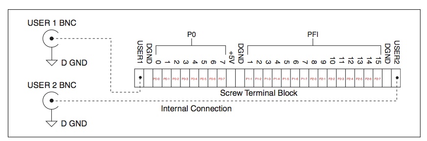
I use a capture card of data NI PCI-6221 connected to a BNC-2090 rack mounting has. Digital I/O Terminal block on the rack mounting sping is a watch the bottom of the image. The PCI-6221 card has 3 digital i/o ports with 8 lines for each port. I tested what line corresponds to what terminal and came up with the following representation in red, where, for example, the P2-2 corresponds to the Port 2 - line 2, etc. However, it seems that Port 1 - 0 line is not represented by a sping terminals.
Is it possible to get an e/s on support for this particular line mounting while I have available altogether instead of only 23 24 lines? Any suggestions would be really appreciated.
Hello
I think you are right that the PFI0 line is not represented by one of the terminals of the spring. Sounds more like it is represented by a BNC connector. You can see that on page 2-1 Manual BNC-2090 is:
-
Is compatible with BNC-2090 PCI-6723 has?
Hi everyone, I am working in a project where I'm forced to use both a PCI-6723 connected to a BNC-2090 case has... In the datasheet of the 6723 only to versions of the BNC-2110 and 2115 are suggested. Anyone know if I can still use the one I have no problem? I mean, it is, is always compatible 2090, do I have to make some adjustments to the hardware/software, or this is just a desperate mission?
Boards are good, thanks for the help.
Hi Jason
Has BNC-2090 is specifically designed for the X-Series, E-series, M-series and S-series.
The PCI-6723 belongs to the series of analog output and for this reason BNC-2090 has not supported this Commission.The best connection BNC block for this is the 2110. This connection block lists the series of analog output as a series of supported.
Concerning
André Director Napoleao
Application Engineering
National Instruments Brazil -
PCI 6221 with BNC-2090 acquisition card
Hello
With regard to connectivity, here is the user manual of the BNC-2090:
http://www.NI.com/PDF/manuals/321183a.PDFExplanations of the it there all pour a measure differential, CSR or NRSE and how to put the switches pour different modus.
In Chapter 2 it is also the comment explanation connect inputs and outputs signals.Nice day
Ken -
How to secure the wiring of digital output BNC-2090
Hi, I'm working on using the digital output of data acquisition to control the digital DAC input, but I have a problem on how to fix the wiring for the digital output of the DAC. When I plug the cable into the hole, it is vaguely related. Any suggestions on how to fix the wiring are appreciated.
Thanks in advance!
It is a spring terminal.
Try to push in the orange tab with a screwdriver while pushing in the thread. Release tab to release the wire, and it must grab and hold the wire. It may be a case involving Orange instead of push. You should be able to understand.
-
Outputs analog BNC-2120 to stop working randomly
I have a BNC-2120 Module. I have the analog outputs implemented with an Assist DAQ. I'm running a square wave, or triangle wave at a very slow pace (.35 Hertz). I'm tracking signals with a waveform graph just before going to the modules DAQ help. The system works well anywhere from a few minutes to 25 minutes. The results seem to just stop working, but I still see the signal on the graphic display of waveform. I think that the BNC-2120 module has some questions. Someone had a problem where the output just stop working? I look in my program of VI?
Hi gwing,.
There could be a few possibilities that could go wrong. Could you upload your code? DAQ hardware do you use with the BNC-2120?
Best regards
Jonathan
-
How to configure 2090 BNC for use on LabVIEW?
Hi all
I'm new on products OR, and I tried to use the BNC connected to a PCI card 2090 6036E on LabVIEW data acquisition. However, I still can't find a way to add this device (2090) to my list of 'Devices and Interfaces' OR max. As far as I understand, this step is necessary to assign the pins and begin to acquire data from the BNC-2090 on LabVIEW channels.
Any thoughts? I would appreciate any help on this matter.
The 2090 is just a silent block of endings. It does not show as a device. You acquire DAQ device - the 6036.
-
PXI-6133 Pulse frequency output and input with DAQmx
I am trying to set a pulse meter output frequency task and read this signal with a frequency counter input task input pulses. I use a 2 PXI-6133, each connected to a BNC-2090 case has. I want to output a square of a certain frequency with the task frequency meter pulse output and then read the frequency of this signal using a task of cost input frequency. I don't know how to property set up these tasks, or how to define which device to use for each heap. I don't know what terminals on the BNC-2090 is the counter of entry/sortient channels correspond to them because that is not displayed in the documentation of the PXI-6133 or documentation of BNC-2090.
Please see the attached VI for my attempt to put this in place. Currently, I get two errors:
(1) error-200452 took place at the property Node DAQmx channel meter Test - referred to as property is not supported by the device or is not applicable to the task.
2. the error-89136 at DAQmx Start Task - specified route cannot be met because the hardware does not support.
If I remove two channels of property DAQmx where I try to put the terminals for the counters, while the program is running, but then I know not what terminals on the BNC-2090 meters are connected to! This causes the DAQmx read for the cost in the tasks of frequency to timeout because it does not detect a signal.
I would really appreciate the help to properly configure these tasks and determine what terminals on the BNC-2090 case has the task of counter will work on.
I see a few problems in the code originally:
- For your CI task, you type is defined as a counter entry > frequency. But on the node property of DAQmx channel for this task, you modify the CI. Property of PulseWidth.Term. It should be CI. Freq.Term. set the entry regardless of the PFI line you do not want the input signal on. Tip: you don't have to type the name of the device in at all. Enter "PFI0", it's the same as "DevN/PFI0" since the unit has already been specified in the DAQmx Virtual Channel Create function. The name of the device, leaving aside will make your code more flexible where you decide later to change the name of the device.
- Maps of the S series, such as the 6133, do not have the same flexibility to change the output terminals of tasks of meter you might find with M or X series device. Page 83 of the S series manual watch what signals can be extracted to PFI lines - Ctr0Out is not one of these. Instead, Ctr0 out is, by default, pin 2. Cabling to a BNC-2090 6133 is certainly difficult to understand out (probably because the 2090 was designed to work with the materials of the E and M series), but if you compare the pinout of a PXI-6255 0 with the 6133 pinout connector, you will notice that they are essentially a match 1-1. Pin 2 is PFI12 on the 6255, so I assume the same for the 6133. All this to say, Ctr0Out always appears on the pin 2/PFI12 for the 6133 and you therefore cannot change the output terminal that your code is trying to do, having for result error-89136. Remove this node from the property altogether and the error should disappear.
-
How to trigger an analog input to analog output
Hello
We have two signals, one of which is a glow that we generate via a PCIe-6361 and a BNC-2110 to my experimental system, and another who is directly related (like an echo) I want to acquire every time that send us one.
What I tried:
-Generating a signal pulse and the bond of an output channel for the PFI0 one.
-Using the pulse generator virtual daqmx (pulse CO-tiques).
I'm sure there is an easier way to do it, but I can't find it, could you help me?

Additional info: attached the two signals (blue, yellow emissions receive), I want to talk.
Thanks in advance!
Assuming you are using the same card for AO and AI, you should be able to use a trigger to start the task of AI with pulse to start the task of the AO.

-
R series connection powered by block and able to connect to BNC
Good afternoon
I recently bought a NI PCI-7811R card in order to get the correct group resolution needed to randomize an excimer laser from the input of a broadcast. I've been putting together FPGA program and during my first test I noticed that the connection BNC 2090 block that we use for all our other activities data acquisition has not been powered. When I bought the card I forgot to buy the block connector as well, thinking that we could use the one we had always used. Well, it turns out that was a mistake. Apparently the R series card is not feeding the 2090. First of all, is it possible to configure the 2090 so the map R series (I don't think so given the conformation of the spindle) fuel and secondly, if this is not possible, is there a connection block that can be powered by the map of the R series which will accept connections BNC. While I think about it, if it is not a compatible BNC connector can I just cut the BNC cable connection and use the wire for the spring Council?
Stan
Stan,
If you are needing some BNC connections, I would recommend just using the junction SCB-68 box and wiring connections BNC yourself.
The CA-1000 is essentially an empty metal box. You can then buy mini-panneaux for what you want to mount. The 2 "included" means that there are 2 BNC connections on each mini-pane BNC. This does not mean that the CA-1000 comes with two mini-panneaux.
Yet once, for only a few connections, if she doesn't need to look really nice and form-taking into account, the SCB - 68 and just a few threads of connection BNC would suffice. If you need more beautiful, the CA-1000 and a few NBC as well as the SCB-68 or inside the CB-68LPR mini-panneaux would work as well.
-
Hi all
My request is configured to synchronously for and very process two analog inputs and generate two analog voltages output.
The application works perfectly but have some problems with a small addition, I try to do.
What I'm trying to implement now is a trigger simple judgment which restores at the same time both channels AO to 0 V.
The trigger of the judgment must come from a simple switch connected to the channel PFI0 of my BNC-2090 / DAQcard 6024E system.
This will serve just as an additional security measure on top of some reliable ones already being implemented.
Following different examples and knowledge base articles, I found that I came with the attached drawing.
While she does not preclude data acquisition and ends the application running it is not reset the OD to 0 (it remains on the last set value).
Any help would be appreciated.
Thank you
Mark
Hi Mark,
Is it not possible to use a function "stop task.vi", by defining the new Scriptures, then using a 'start task.vi' before clearing after your loop? This way you can be clear that original AO task has stopped executing before changing the values being generated.
Kind regards
-
Hello
I use a transducer of pressure with a maximum flow of 100mV. I connected this pressure for an SCB-68 transducer that is connected to a PXI-6289. The transducer is connected in differential mode (ai0 & ai8). I'm supposed to measure a constant balance no when I turn on the transducer (10V DC) without differential pressure applied to the transducer output from - 5 mV to 5mV.
The problem is:
I measure a zero balance output, but the value continues to decline (even after 50 minutes). If out of balance zero is negative, the value decreases yet (he does not lean towards 0).
If I connect two transducers on different channels, zero out of balance (which is not the same thing, according to the serial number of the transducer) will decrease at the same rate.
What I tried:
I tried another power supply
I tried to measure CSR and NRSE
I tried with another station of PXI
I tried with BNC-2090
I tried with the PXI-6224I tried with other sensors of serial number (3 different with all the same problem)
I tried with other cables
I tried to measure in a different location using a different power source
I tried to reduce drastically (from 10 k to 1 sample per second), the sampling rate
ALL these failed to solve the problem.
I have contacted my provider of transducer. He has guaranteed that these sensors should keep their zero balance production constant for 4 years. Also, the fact that the rate of decline is almost the same thing when I connect different transducer would point to one reason other then the sensor itself.
Here is an example of a test (about 35 minutes). The tension is out of balance zero. Unknown event caused a rapid fall in the beginning.
Hoping to get a quick response,
Elliot
-
Requirements for data aqusition for body MeltMC
Hello.
Let me Preface this post with the fact that I don't know anything about the material.
I'm trying to compile something that will be used to raise the temp of body at different points on a body of people on
several hours. The device must be relibable, but I'm also looking for something that I myself will be able to understand.
A similar study used the following.
16 Thermistors (type MA100GG;) Thermometrics, Edison, NJ) connected by a linear voltage divider (10 resistors k. ± 5% accuracy)
BNC-2090 A/D Board
LabVIEW.
To reduce the impact of failure of wire, thethermistors were connected to the acquisition system of data with a 28 gauge wire.
16 voltage dividers were organized in parallel, and the circuit was fed to 0.5 V (power supply model PS280;) Tektronix, Inc., Beaverton, OR) to minimize
(self-heating thermistor< 0.01°c).="" data="" from="" all="" 16="" channels="" were="" simultaneously="" collected="" at="" 1="" hz,="" and="" the="">
adjustment of the curve was used to calculate the temperature of the measured output voltage.Please let me know if I can move it a more appropriate Board.
Thanks, J
Hello J,
A set of material for 16-channel thermistor.
All of the following materials is recommended for this requirement at lower cost:
SHC68-68-EPM cable and 1.PCI - 6221, http://sine.ni.com/nips/cds/view/p/lang/en/nid/14132
2.SCXI - 1349 Adapter PCI-6221 and SCXI, http://sine.ni.com/nips/cds/view/p/lang/en/nid/1627
3 SCXI-1503 and 1306 16-channel thermistor, http://sine.ni.com/nips/cds/view/p/lang/en/nid/204198
You can use LabVIEW SingalExpress that comes with the equipment to record the data, or if you want to do further analysis, LabVIEW can also help.
You don't need to calculate the temperature of acquired resistance.
Software will display a temperature directly, but you must enter a correct setting of the specification of the thermistor.
Sincerely, Kate
-
I need to perform data acquisition for my sensor of temperature RTDS (PT 100). My sensor is first attached to the converter temperature Broderson PXT 10, then to BNC-2090 - NI. national instruments DAQ board.
PXT 10 gives 0 - 10V DC output, which is then provided to BNC-2090.
While BNC 2090 reads only the voltage, data acquisition give some readings of voltage. I want to know how I can convert the resulting voltage reading DAQ corresponding temperature.
Currently I use Callendar Van Dussen equation for conversion. As I take a very low current exciation, conversion gives me a thousand ohms resistance values, and that's why I don't get the value of the correct temperature. I have attached a reference image.
Can someone please help?
Thank you.
Raphael,
Even if the plug is not explicit, the implication is that output (0-5 V) is linear in the selected temperature interval. So 0 Volts would represent - 50 C and + 5 V would be 300 C or C 100 depending on the range. All you will need is linear (m * x + b) scaling for temperatures.
You must run probably some simple calibration verification tests to make sure it works that way.
Lynn
-
Hearing feedback in real time program: hardware configuration
We had access to a LabView (of another laboratory) program that records the sounds and gives audio feedback in real-time based on the analysis of the spectral structure of the input sound. The current combination of equipment that we have in our lab is the Daq 6259 PCI card and a BNC-2110 connector. The laboratory of donors had run a set consisting of PCI 6221 Daq card and connector BNC-2090. I'm studying the manuals for the four pieces of hardware to determine if our hardware configuration can be used with this LabView program. The main difference I found is that the connector BNC-2090 has DACout connectors, which lacks the BNC-2110 (my setup). I don't know if that alone will make it unnecessary for use with this LabView program.
I continue my study of textbooks to go further, but it would be useful that some experts could give its opinion on it. In this way, I could do a faster purchase decision.
Thank you!
Anand
Hello Anand,
2110 has analog output BNC connectors that expose up to 8 channels of analog output on your Data Acquisition device. Please take a look at the below picture of the BNC-2110 (page 3) user manual and following section which discusses the analog pins output BNC (page 6).
Best regards
Izzy O.
Technical sales engineer
National Instruments
NI.com/support
Maybe you are looking for
-
Process of Firefox starts but doesn't show main window
Hello Since a few days, I can't start Firefox. The beginning of the process, but hangs with a memory fixed space and zero CPU usage, and the main window simply will not start. No accident report is created. Kill the process and try again is the only
-
If I can exchange my ddr2 with ddr3 memory modules in ideapad y530?
-
I can't find Canon, (canoscan LIDE25) on my list of scanners
I can't find Canon, Canoscan LIDE25 on my list of scanners, difficulties to download the drivers for this device. also I have more Moose record for the scanner It worked before this computor, until I turned power off the POWER for a week then he's on
-
Settings of Windows Live has stopped working.
Message: A problem caused blocking the program works correctly. Windows will close the program and notify you if a solution is available. (Never notified). Best Buy re - install Windows but this nature occurs. It was very expensive and would like to
-
No audio signal from the forced update. Can not restart Windows Point of service endpoint
I now have 3 unnecessary Windows computers and 2 printers useless because the new drivers do not work. Computer 1 forced to W10 and I can take it is no longer online or the display driver is updated and I have a black screen. Computer 2: I tried to r