No count output / pulse pulse does in a meter of pcie-6320
Hi all
IM using pcie-6320 in my application to generate impulses using the counter i/o.Even when I try to generate/counting pulses using MAX, I coundnt find no exit, im watching the e/s using a CRO. My camera works very well and tested hardware DAQ Diagnostic Utility tool in this tool also spent the meter test. IM completely stuck here, if anyone has come across such a problem please help me.
Hello.. I solved the problem. In fact, it was found that the cable between junction box and data acquisition is not properly inserted. In any case thanks for your contributions
Tags: NI Hardware
Similar Questions
-
Hello
I would like to know if there is any couters who can count CMOS output pulse.
The coast of CMOS pulse are:
Pulse output: 5 v CMOS
Output pulse width: 10 ns
(It is actually the output of the unit of counting photons Hamamatsu C9744)
I have some cards PCI (6014 and 6110), but their logic of meter is not TTL, CMOS.
When the CMOS output is connected to a meter of these cards, the number of meter
has increased, but it may not be a correct counting.
If you have a good idea to count with the products OR, please let me know.
Thank you for your time and your help.
Hiro
Hey, Hiro,.
The essential is that a TTL meter will be able to read the introduction of CMOS, but not the reverse. Therefore, you are OK. This is mentioned in the last line of this link: http://digital.ni.com/public.nsf/allkb/5AB6172CAE2BEF3E8625629800597B3F?OpenDocument
An explanation of the thresholds of tension associated with each level in the chart in this link:http://www.interfacebus.com/voltage_threshold.html
The counters on your devices covered by standards TTL/CMOS, who can count a pulse input CMOS. Some general information on each standard can be found at this link: http://digital.ni.com/public.nsf/allkb/2D038D3AE1C35011862565A8005C5C63?OpenDocument
Kind regards
Jeff L.
-
Salvation;
Here is the solution for your problem.
The cause is that "Gen dig Pulse Train-Finite" uses Ctr0 both Ctr1.
Please refer to:
"When you do a finite pulse train generation, a counter generates pulse train, and the other counter generates an impulse that acts as a barrier to the first counter. If you change the pulse train to generate continuously or
only generate a pulse, you can run two tasks of meter at the same time without error. »
http://digital.NI.com/public.nsf/allkb/04BEDD9E9E91ED3486256D180048116D
I used Ctr0 and Ctr2, jumping Ctr1 as it is reserved by "" Gen dig Pulse Train-Finite ". I works very well.
Kizito.
-
Hello everyone,
I need to count the pulses of a digital signal. I looked at the examples associated with it, but all seem to use a signal acquired by a digital counter entry. I already have the signal in my computer, so using a device entry makes no sense. And the library of functions, I looked but found nothing. What features LabView should I use?
Thanks in advance for your time and help,
Pablo Concha
You can go there. 8.2
-
count the pulses ttl only on 2 V
Hi I have a problem while I was trying to count a pulse ttl using the DAQ Assistant. The problem can be simple, but I just can't solve that since I'm new to LabView.
There is a TTL pulse produced of our ODA that is about 30 ns width, 5V. I want to use LabView to perform the count of photons. But because of the noise, I want to put a number limit of 2V, so the software one count higher than 2V TTL pulse. But I can't do that. There is no option to set the limit.
And our material is BNC-2110 and PCIe-6323.
Can someone help me with this? Thank you.
For a counter entry, the minimum voltage for logic there is 2.2 volts - a ttl level. And no, you can not adjust higher.
-
How to use the NI9403 module for counting of pulse device? We test engine GE ECM and provides a signal of 32 pulses per revolution.
Hi Change_Air,
In short, you might want to consider another module (probably a 9401 or 9402 according to the type of desired connector and/or the number of lines required).
Modules with 8 lines or less (e.g. 9401, 9402) use a dedicated line to transfer the data from each of its inputs on the chassis backplane and are therefore capable of routing of external signals such as timing/triggering signals (for example one of the counters on a backplane cDAQ). However, modules with more than 8 lines must transfer the data serial to chassis backplane and so tickets are not available for routing.
Assuming you are using a bottom of basket cDAQ newest (any carrier except the x 9172 or 916 cDAQ), from 9.3 DAQmx you can configure a sample clock and acquire a digital input buffered on modules that transfer data in series (I think the 9403 can taste up to 1/7 US = ~ 142 kHz). So you could end up with a table in the data buffer (for example [0 0 0 0 0 1 1 1 1 1 1 0 0 0 0 1 1 1...]) which you could then analyze to determine the number of edges. Of course, the impulses must stay high for at least a period of your sample clock to ensure that you are able to detect.
If you're on cRIO you could set up something similar, but the same restriction applies always - the limit is the maximum rate that data can be transferred in series of the 9403 inside of basket.
Thus, although it is probably possible to get what you want with the 9403 (according to your pulse width), a "parallel" module would be much more effective in the detection of the short pulses (if it was a requirement) and would be simpler to program as well - you could just set up a task of edge with a meter count (assuming that the cDAQ). There's a Developer Zone article containing a list of all series C, but it seems to be incorrect for several modules (perhaps an employee NOR will see this) about the nature of the series/parallel data transfer for the DIO modules. I am not aware of any exceptions (and do not think that there should be none) to the rule that modules DIO with 8 lines or fewer are 'parallel modules' and DIO modules with more than 8 lines are "serial modules" (there are rows of data exactly 8 connector d - SUB between each module and chassis).
Best regards
-
How to count the pulses with digital input on 6351
Hi all experts in Labview,.
I just got my USB x series 6351 and it works fine, but I certainly lack of labview skills to use it to its full potential.
I would like to read digital pulses with several digital inputs and count the number of pulses each T interval in time. All impulses that I entered on any edge of the clock are not synchronized and can occur at random times during the tests. Basically I have an oscillator of square waves can I modulate the frequency. I don't want to use the meter as inputs as I'm limited to only 2 entries (if I use the option 2 input meter for metering of pulses or frequency). The input frequency can range from 0-1 kHz and goes 0 - 3V. So not too fast, and I shouldn't make too many mistakes trying to get the count of pulses and then back out the frequency in accordance with article ni.com on counters.
I would like to read the 8 digital input channels and get the number of impulses for each channel. I searched high and low for help online but can't find examples that have been useful. Anyone have any ideas on how to go or direct me to a resource? Thank you very much in advance!
Are you worried about getting the number as a physical operation timed? It would be nice to acquire a digital waveform and then postprocess on it to detect how many events took place? I've attached an example that shows how you can accomplish this. It reads a digital waveform and then uses a detection of crete VI to determine how many pulses occurred. Should be a few adjustments to your particular signal. The VI I use seems to count events twice (probably count each edge), so counting it gives should be reduced by half in order to work.
-
How to count the pulses using RIO (FPGA)
Hello
I want to use RIO (FPGA) for counting the pulses produced by a sensor,
but I don't know how to program. can someone help me.
Thanks in advance
CAIX wrote:
Hello
I want to use RIO (FPGA) for counting the pulses produced by a sensor,
but I don't know how to program. can someone help me.
Thanks in advance
Search for example for 'Meter of RIO' finder. There are dozens of examples that should help you.
-
Hello!
My problem appeared when I tried to update my traditional NOR-DAQ legacy code to DAQmx.
I use 2 meter (meter 5 and 7 meter) on PCI-6602, to generate trains of pulses, as well as the lines of e/s digital port 0 (the form lines from 0 to 7). What I do in my request, it's that I'm starting to generate the pulse train on the output of 2 meters and after that I play with the State of digital lines.
Traditional, it was no problem to use the meters and digital lines at the same time, everything went perfectly, but in DAQmx, is not possible.
What's happening: I start generating train of pulses on the output of counters, no errors, but when I try to change the State of a line of digital port the generation of the pulse train is stopped. What happens when I start the task associated with the digital way.
My question is: is it possible to create a channel on digital lines without changing the channels created for meters?
Another thing that I managed to do with the panels 'Measurement and Automation Explorer' and Test for PCI-6602, is basically the same thing, I generate trains of pulses on the output of the 7 meter and try to start a job on the digital line, but I get an error:
"Error-200022 occurred in test Panel.
Possible reasons:
Measurements: Resource requested by this task has already been reserved by another task.
Device: Dev4
"Terminal: PFI8.On the contrary if I use the counter 0 or a counter 1 to generate trains of pulses I encounter the same problem.
What resources are used by 2 to 7 of the PCI-6602 card counters and the counters to 0 and 1 do not use?
Thanks in advance for any answer!
Ciprian
After doing some real tests on this device, I found that it is a normal behavior for the jury of 6602. This is because when you start a task digital all 32 lines are configured for digital i/o, so it replaces your meter operation. The article below the link explains a little more on this subject. You must start the digital task before the task of counter to use the features of both in your program.
2 meter and above will not work correctly when you perform digital i/o on NI 6601 or 6602
http://digital.NI.com/public.nsf/allkb/43F71527765EEC3886256E93006CD00C?OpenDocument
-
Pulse train generation question-PCIe-6320
Hi all...
IM using PCIe-6320 series daq x to generate trains of pulses. I went through the examples found in the labview to generate digital impulses. Provided vi runs without error, but I could not find any pulse output in my PIN ctr0. Is there a specific connection to check the output?
Hello..
I had a problem with the interface cable, I found this later.thanks.now I havesolved.
-
The right click "rotation" clock or function in a clockwise direction counter on my images does not work
There is a range of adjustment that may be messed up?You are under Win XP and the display of photos with Windows Picture and Fax Viewer?
Explain what you mean when you say "does not" you receive an error?
The following command will force a reinstall of Windows Picture and Fax Viewer and can be worth a try:
Reach... Start / run... and type
(or copy and paste):regsvr32 /i shimgvw.dll
(Yes, the space after the 2 and the)
After the i is necessary)Press on... Come in...
You should see a dialog box stating:
DllRegisterServer and DllInstall in successful shimgvw.dll -
XP mode does not recognize my 6023E PCI card
I bought a new Win 7 with a PCI slot inherited to execute an OLD NI PCI-6023E card I used for years. I downloaded the drviers legacy NOR (7.4), but he does not see the card. When I look in Win 7 the card is there but I can't run the 64-bit drivers testament and with my old software (C++). I have connected a NI USB-6008 card and was able to open the card in XP mode... any ideas?
Unfortunately, XP mode does not work with the PCI/PCIe devices, only those USB. Most (all?) programs virtualization will have this limitation.
As you probably expected, the General recommendation is to migrate to the API OR-DAQmx for your application if you want to that support on Windows 7.
If this is not possible, then there is a section of the knowledge base on a Beta OR-DAQ traditional (old) for Windows Vista and 7 , who might be interested. At a minimum, it will take allows you to use a 32-bit installation of Windows 7, not a 64 bit.
-
Hello
I have a power meter which provide the USB driver and a Labview program to get the data and NI USB-6221. The project I am currently working on the needs of:
1 acquire two signals (inputs of simple tension), pressure frequency KHz
2. acquire a flow signal, the output signal is 0 to 5V pulse, each pulse means 0.4 ml volume. So I use a voltage inflows to count impulses in certain period of time (in this case, 1 S) for water flow. ; KHz sampling frequency and the 1 Hz update rate
3. acquire a signal of engine speed. The output signal is pulse square wave whose frequency is related to the speed. I use a REIT port to measure the frequency. Sampling rate: Auto
4 give output voltage sine or square wave, I use AO do that.output rate: Auto
5 acquiring by VISA electricity meter data. Data update rate: every 50ms
Currently, all the 5 tasks work well separately. But when I put them together, some signals are beginning to hang, for example, pressure signals sometimes give nothing.
Another problem is the data record. I programmed the VI in such a way that whenever I press the button 'save start', he begins to record data and save them in a .cvs file. For some reason, I always get only the data in the first table. Coult someone help me? I download my code as follows
Hello
What I meant by open, write, close. For any type of file you are using.
Open the file, which produces a reference, then put the mention in a registry to offset.
Write data, using the function write (for this type of file) and the reference.
When you are finished, close the file reference.
Writing in the spreadsheet opens, written, close all at once. It is very good for this type of application.
***
The issue of the loop is more general. I would like to say first of all, I want to say that since each loop works on its own, it is own VI, and that this program has put all this into a single VI, which has a method to solve the problem is to disable all the loops and allow them one at a time to see if there is a culprit responsible for.
Using multiple loops executes the code at the same time, and some loops would be cycle faster than others, especially if some of them are loops just as they are.
Communication between the loops is a test to the address if necessary.
Running all these signals through different loops DAQ must also be examined. Don't know what questions are for read and write somewhat randomly in the channels.
-
9174 triggered output pulses and analog input synchronization
Hello
I have a cDAQ 9174 with a 9215 analog and a 9401 module. I wonder if this configuration is suitable for my use: a trigger digital extern is sent to the system to trigger a task of analog input, trigger a generation of pulses, with another counter, count of trigger events. Using two counters on 9401, it seems I have no left Terminal at the entrance of my trigger signal. The trigger DAQmx vi does not show counters entries in the list of signals; and if I select a PFI line, an error that says that the line is already in use..., I missed a few obvious solution? I have change my 9401 to a 9402 did?
Thanks for any help,
Vincent
Hi Vincent,.
So, looks like you need a single line to use as input to trigger events and another line to use for a generation of pulse output. This should indeed be possible, since the 9401 has 8 lines that are configurable nibble (i.e. lines 0:3 could be configured as inputs, while the 4:7 lines could be taken out, or vice versa).
However, a big caveat with the 9401 is that the lines must be reserved before each task is started. This is a limitation of the direction of the line is implemented in hardware and is common as customers when something they using the 9401. Explicitly reserving your tasks before starting must correct the behavior if that is indeed what you see.
Best regards
-
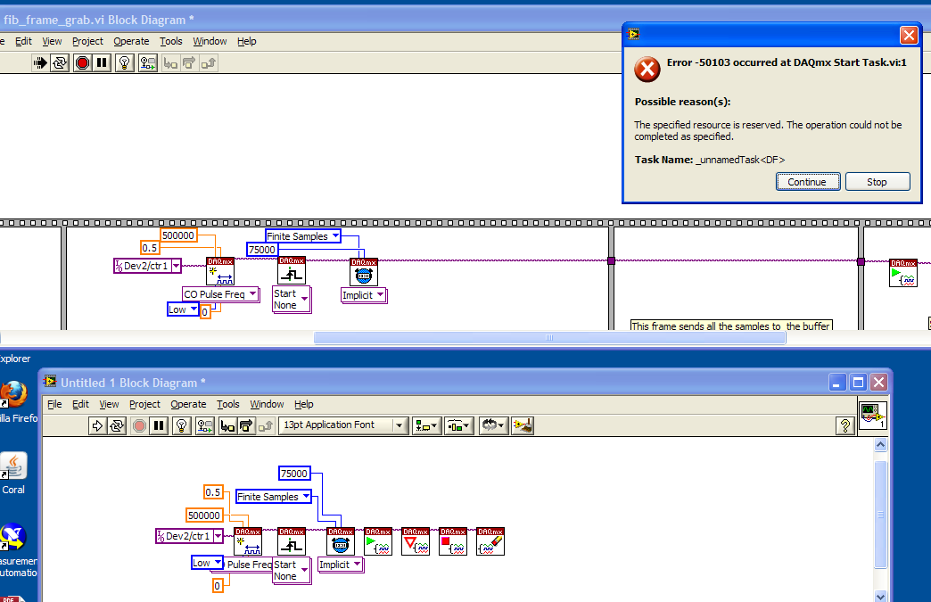
Counter/Timer Pulse Train generation
Hello
I'm having some difficulty to understand why a particular VI I does not work (upper part of the image below), I was wondering if someone could give me an idea of the cause of the error message. I have a counter/timer, which I use to generate a pulse train. It works very well on samples of "continuous", but when I turn it on to 'finished samples' I get an error of "resource is reserved" when it comes to the DAQmx VI of 'play '.
I made an another VI (lower part of the image) and it works very well with finished samples. So basically I wonder what's different on finishes versus continuous sampling which could cause a resource to book or not. (the Board of Directors is a PXI-6281 if it matters)
Thank you
Adam
OK, I just looked through the manual and it seems that when you do a finish on a counter pulse train generation, the jury must in fact to divert the OTHER counter.
This may have been aparent earlier if the error message about what resources he tried to get was more prolific.
In any case, problem solved I guess.
Maybe you are looking for
-
iPhone 6s more Resulution of camera?
A long-time member of Apple, first post time. I have an iPhone 6s more 16 gb Black, I have questions about the camera... First, I will say I know resulution databases and all that. I know that the camera can record 4 k Resulution I lit this setting a
-
[Z510] Problems with the battery not charging
I have ideapad z510 for almost a year. and now my unit still shows that it is at 0% battery. and she indicates that she battery level does not increase. and for this reason I could not use my unit when it is not plugged. What should I do about it? Co
-
VOIP Monitor is OUT of SERVICE on UCCX - 9.0.2 - 9.0.2.11001 - 24
Hi All - Recently updated UCCX up version 9.0.2 in CRAIG configuration, where VOIP MONITOR is OUT of SERVICE on the node of the Subscriber. Restarted cluster - No go Any idea? 1492016: 24 July 14:53:10.175 GST % MIVR-SS_VOIPMON_SRV-3-operation for th
-
Windows 7 wireless connection problem
I just bought a brand new Alienware m17x and all drivers are up to date... .IM with broadcom wireless network adapter. The strange thing is that last night I was on the internet for several hours without any problem using the wireless, but this morni
-
Connection spoke to talking DMVPN
Hello world You will need to confirm on DMVPN say if R1 is the hub and R2 and R3 are spoke. Need to talk to R3, R2 if it will use PNDH and go via R1 to R3? Is it possible that R2 R3 can talk directly using PNDH? Concerning MAhesh