How to measure width of digital pulse using SMU-6548
Measure the digital signal of high level pulse width (a few seconds)
1US accuracy requirements
Thank you
Hello
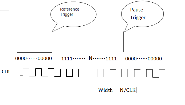
You can configure the trigger of the reference and the break, and you will get a table as below. Calculate the number of 1,
The pulse width is N/clock.
Tags: NI Hardware
Similar Questions
-
Change the width of digital pulse inside the loop
Hello
I am looking for a solution that allow you to change the width of digital pulse inside while loop.
Thanks in advance
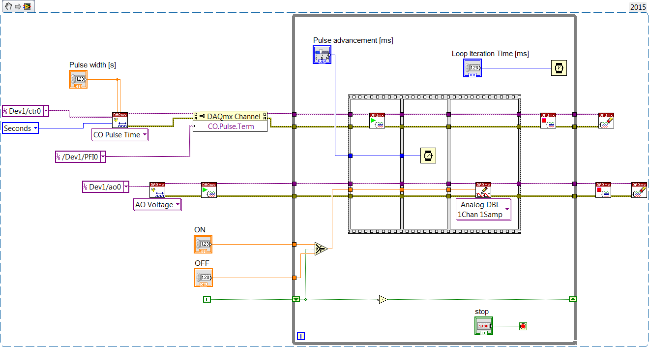
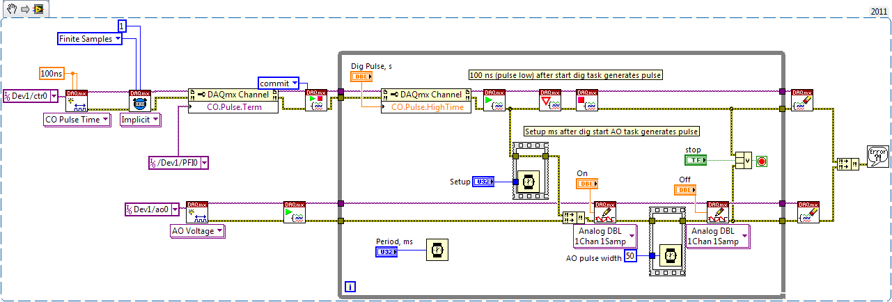
Check the operation of dataflow and single pulse meter output
First counter generates little time, then big time.
Your AO task then is to adjust tension on IT after Dig pulse. After the AO pulse width, he needs to put down
If the Trac software is small enough for you, you might have used USB-6008 ($250), not Xseries $ 1600 - apparently of an overdose. X series can do this work with a void microsecond resolution.
-
How can I resize a digital image using software of photo gallery to keep my digital images to be cut during printing on standard paper by a commercial processor? MP
How can I resize a digital image using software of photo gallery to keep my digital images to be cut during printing on standard paper by a commercial processor? MP
====================================
Sometimes the only resizing is not the answer because the
the original size is different from the print size.You may need to crop photos to the size you want
print to ensure that no clipping will occur. Cropping
to a different aspect ratio will lose some parts of the picture but
at least you have control over it.Windows Live Photo Gallery is a cropping tool.
Volunteer - MS - MVP - Digital Media Experience J - Notice_This is not tech support_I'm volunteer - Solutions that work for me may not work for you - * proceed at your own risk *.
-
How to measure the frequency of NOR-DAQmx RPM tasks
Hello
I'm trying to measure the frequency using the NI DAQmx task and then convert it to a RPM if possible.
I have the following material available to me.
I have a block SCXI-1327 terminal, as well as a 6289 PXI multifunction data acquisition Module SCXI 1126.
I wired in a mag ai7 sensor on my 1126 and then of the passage of an object metal I get a range of 6-8, so I am able to read the mag sensor.
What I'm trying to do is somehow convert this analog measurement a RPM using the NI DAQmx task only.
Any help would be appreciated.
Hi, smooth,
Yes, you would select linear, then put in the result of this calculation of the slope.
The Manual recommends a minimum frequency of at least 15 Hz for setting low range. This card is not really designed to measure the frequency for a single pulse over a long period of time.
The number of LAPS down (assuming one pulse per turn) that we recommend that you measure with the 1126 is so 900 RPM. If you need measure low revs, and you cannot increase the number of impulses per turn, you could consider either read the signal as an analog waveform, or if it's a digital pulse, using a counter to basic task. In this way, you can use any method you want to handle the situation where there is only a single pulse in a long time.
-
NI6602 pulse width measurement: do I have to use an external sample clock?
Hello
In the example .NET 4 "MeasPulseWidthBuf_SmplClk_Cont", it is said in the comments that:
An external sample clock should be used.
Hi mola.
This specific example measures of sample-clocked pulse width. This type of measure is supported only on new hardware such as the X series cards and will not run on the 6602.
Your application that you have linked uses Implicit timing, which means that the signal is using the sample clock. In other words, at the end of each pulse duration which can be measured, the sample is deterministic locked in. So you end up with a table in the buffer of each pulse width which is seen by the meter.
Best regards
-
Measure the time of the rising edges of a digital stream using a USB-6341
I have a DAQ USB-6341 map.
I use Measurement Studio (writing code in c#) on a Windows 7 computer.
I'm relatively new to the DAQ cards, programming, so I could ask something that is obvious (sorry if this is the case).
I went out a stream of digital pulses to an analog output channel. I wired this channel to one input of the meter channel. I am able to measure the number of edges upward to the inlet of the meter channel (since the digial flow is continuous, the number of rising edges increases with time).
I would like a time stamp of each rising transition and I like to keep these timestamps in a table without ever growing (or maybe bin these timestamps in a histogram).
Set up the meter channel to provide the timestamp data? (rather than just count)
Thank you for your help.
WRB,
The meter must be able to measure the relative time between the different edges of your signal. To do this, you will take care to set the meter to measure time. It will measure how long a full period of your signal takes. You can configure edge that you want to start with. You'll want to set up your timed 'implied' measure. This sets up the meter to automatically take action whenever a period is over. While it's not exactly a timestamp, you can find the distance between two edges by adding the time periods between the banks in question.
I see another technique that you can use. This would put the counter to edges of County one of the basics of time of your device (it has 100 KHz, 20 MHz and 100 MHz bases long). Then configure the task to use your signal as a sample (configuration to use rising edge) clock. Whenever the song occurs, you will get the number of ticks ticks selected timebase that took place at that time. One thing to note here, however, is that the counters are 32-bit wide, so your code will have to manage the overthrow of this charge if you are using a fast time and base running for long periods of time.
Hope that helps,
Dan
-
How to measure the frequency of a clock using meter in LabVIEW?
Hi guys,.
Someone knows how to measure the frequency of a signal introduced in LabVIEW (in the FPGA PXI-7813R), using a counter in LabVIEW?
Essentially, I want to use this counter as a kind of Logic Analyzer.
Thank you, Anoop
I don't know what you mean by "manual". It is all managed in a housing structure.

-
How to measure high voltage (60-70 v) and current (75-80 a) using a DAQ PCI or USB DAQ
Hello
I work with a system that works on about 5kW. The output of the system voltage can go maximum up to 60-70 v and thus the corresponding current around 75-80 a. I have 10 these systems that I want to read one by one continuously for long periods.
I am designing the automated system best suited for this and looking for the best material that would be appropriate for this purpose. Looking for options, I found that an SCC - A10 attenuator may be used to get the tension down by a factor of 10. But I'm confused, if the high current will pose a problem and also how to measure this high current.
I need to measure the voltage and current at the same time. Please suggest what would be the most appropriate fitting for the same (preferably PCI or USB)
The hope of a quick response. Thanks and greetings
Reena Sharma
Facilitated learning
Reena says:
Hi all
There is good news that the idea of using a compact data acquisition has been accepted by the authorities of the society. I'll be very grateful, if you could suggest me with some hardware modules suitable for my application and how I can use them best.
Thank you very much
Reena
I was able to make a few suggestions, but do not have the time to understand your needs and the forums are not the best solution.
Your Local OR representitive actully gets paid to do this kind of thing. a google search suggests THAT LME is in Pasadena. Zack Collins would be the contact rep
-
Using SMU 6612 to measure PXI-6528 pulsewidth channel - channel is not available.
Hi all
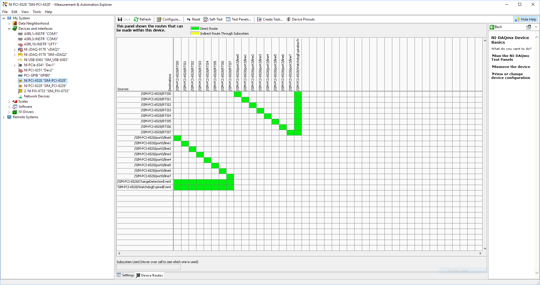
I use SMU 6612 card counter to measure the pulse width of the signals to PXI 6528 DIO card. These two cards are in the same chassis PXI (NI-SMU-1065). I could measure the pulse widths using the example LabVIEW 2013 Counter - pulse width of reading and (over) frequency example of .vi. However not all channels of the PXI-6528 map appear in the drop-down list of channels on the pulse width can be measured. Try to connect any other channel that those which are available in the drop-down list returns the error. On the PXI card port 6528 0,1 and 2 are entered ports and port 3-5 are output ports. I can measure the pulse on port 0, 3 width and line 0 port 1 and 4.
Can someone explain to me why don't see port 1 or port 2 channels in the drop-down list or force the VI to measure the width of pulse on these channels?
I can plug PXI-6528 external input channels SMU 6612 counter input channels and measure the pulse width, but if possible I'd like to avoid the external wiring between the 2 cards.
Probably not. Unless the routing plan is in fact reversed as it seems a bit sorta that. As stated on my system, you can route * of * a port of entry * to * RTSI, or you can route * of * RTSI * to * one output port. This does not make much sense to me, but that's what I see:
If the routing card * is * reversed, your only likely workaround without physical wire would be to generate impulses in question of port 3. It's pretty clear that 1,2,4,5-tetrachlorobenzene ports have no ability to interact with the bus timing, physical wiring would be the only option.
-Kevin P
-
How can I get the digital power meter?
How can I get the digital power meter?
I use a method similar to the example below to measure the market factor using the inputs of a multifunction data acquisition meter. If the duty cycle is 0% or 100% for a given period, DAQ reading times out and returns an error. In this case, I would get the digital state of the counter of entry so I can put as cycle to 0% or 100%. I want to do it without knowing the digital port and line the entrance of counter... for example I would like to continue referencing DAQ/ctrX since I already have this information.
The application uses an M series: PXI-6229 DAQ and LabVIEW 2011 to make a system customized for VeriStand.
https://decibel.NI.com/content/docs/doc-12396
For the moment I wired the block diagram to add a case structure to check the meter ID and string constants to set the identifier of digital input, as they share the physical connection. As much as I can say that makes the specific code for the PXI-6229 (or any DAQ with only two counters that share connections with p2.1 and p) 1.4
I have attached the VI sub.
When the device is used with a different data acquisition, I can add the connection and/or separate control. Looks like at least one will be necessary given that the meter can only detect the edges... I think it was the piece of information I needed.
Thanks for your help!
-
Redeclenchables pulse using GPCTR0 on 6062E STC
I have the desire to have an external synchronization signal (too short a duration) detected by a jury of 6062E and output a pulse of longer duration as a timing signal that I would read on an analog channel as well as other sensors on other analog channels. I used the example program 2055.zip, STCgeneratesinglepulse, for LW/CVI as a starting point. I modified the sample program so that it is redeclenchables instead of just pulse. This code example uses GPCTR0. The program works but not as I expected. GPCTR0_OUT has the pulse output generated and programmable duration that I want. GPCTR0_GATE is the input trigger/sync signal. What I've found, is that the DOOR has a constant voltage of + 5V signal. The problem is that the only trigger that works is an intermittent grounding to the GPCTR0_GATE. I was keen to work with external synchronization signal (short signal down-up-down). I was using the DAQ card + PIN 5V power to mimic an external trigger. How can I use such a trigger signal to generate the impulse? I have included a stripped to the low, short version of the revised program sample below and also as an attachment.
#include "nidaqex.h".
/*********************************************************************
* Sample program: based on 2055.zip
* STCgenerateSingleTriggeredPulse.c //changed to redeclenchables
*
* Description:
* Generates a redeclenchables digital pulse 1ms LOW and 100 ms HIGH aid
* General counter 0 after tripping (for devices with the)
* Acquisition of data-STC counters/timers)
*
* Pins of connection information:
* Your digital output pulse will be on the GPCTR0_OUT pin (2 for 6062).
* Connect this output to an analog channel for time synchronization w / normal DAQ.
* Connect your trigger pulse for digital on PFI9/GPCTR0_GATE spindle (3 of 6062).
* Plug the Locator on the ground at the 'digital ground' PIN (4 / 18 of 6062).
*
* To trigger, connected to pin 3 on the ground. But this isn't what I want.
* Want relaxation to be a HIGH LEVEL of BASS. How?
*
* The presence or absence of next line had no effect.
* Secret = GPCTR_Change_Parameter (iDevice, ulGpctrNum, ND_GATE_POLARITY, ND_NEGATIVE);
*
*********************************************************************
* Used a second computer/data acquisition monitoring system.
Monitoring system connected to the DAQ computer
* ---------------------------------------------- -----------------------
* ACH0 (68) GPCTR0_OUT (2)
* Rider to DGND AIGND (67) (4) ACH8 (34)
*
* OR
*
* Use the counter on the second computer/data acquisition monitoring system.
Monitoring system connected to the DAQ computer
* -------------------------------- -----------------------
* GPCTR0_OUT PFI9/GPCTR0_GATE (3) (2)
* GND GND
*
*********************************************************************/void main (void)
{
char c; for the test
I16 Secret = 0;
I16 iRetVal = 0;
I16 iDevice = 1;
ulGpctrNum u32 = ND_COUNTER_0;
u32 ulLOWcount = 100; 1ms
u32 ulHIGHcount = 10000; 100ms
u32 ulLOWcount = 2; 0.02ms
u32 ulHIGHcount = 10; varied 0.1ms for testing
Secret = GPCTR_Control (iDevice, ulGpctrNum, ND_RESET);
Secret = GPCTR_Set_Application (iDevice, ulGpctrNum, ND_RETRIG_PULSE_GNR);
Secret = GPCTR_Change_Parameter (iDevice, ulGpctrNum, ND_SOURCE, ND_INTERNAL_100_KHZ);
Secret = GPCTR_Change_Parameter (iDevice, ulGpctrNum, ND_GATE_POLARITY, ND_NEGATIVE);
Secret = GPCTR_Change_Parameter (iDevice, ulGpctrNum, ND_GATE, ND_PFI_9); Gate, apply trigger here
Secret = GPCTR_Change_Parameter (iDevice, ulGpctrNum, ND_COUNT_1, ulLOWcount);
Secret = GPCTR_Change_Parameter (iDevice, ulGpctrNum, ND_COUNT_2, ulHIGHcount);
/ * To print a counter pulse, you must call Select_Signal. */
Secret = Select_Signal (iDevice, ND_GPCTR0_OUTPUT, ND_GPCTR0_OUTPUT, ND_LOW_TO_HIGH);
Secret = GPCTR_Control (iDevice, ulGpctrNum, ND_PROGRAM);
printf ("apply your trigger pulse to PFI9 now. \nThe rising edge is armed and the second falling edge is in the value. \n") ;
c = GetChar (); This simulates normal DAQ.
Secret = GPCTR_Control (iDevice, ulGpctrNum, ND_RESET);
/ * Note that the following call to Select_Signal causes the
output high impedance that will probably bring the logic
HIGH level, if there is a pull-up on this PIN resistance. (Check your)
Manual of equipment.) If you do not want this behavior, comment
the next line. */
Secret = Select_Signal (iDevice, ND_GPCTR0_OUTPUT, ND_NONE, ND_DONT_CARE);
return;
}S_Hong,
I solved my problem.
I had in my code
iStatus is GPCTR_Change_Parameter (iDevice, ulGpctrNum, ND_GATE, ND_PFI_9);.
and was my trigger for entry. This is false because PFI_9 is an echo out of everything my trigger is connected to.
I changed the statement to
iStatus is GPCTR_Change_Parameter (iDevice, ulGpctrNum, ND_GATE, ND_PFI_0);. for the source of the signal.
and now a trigger on the PIN PFI_0 generates the impulse.
-
How to generate a variable frequency pulse train constantly
Hi all
I am using NOR-USB-6259 (BNC) to send signals of impulse to the position of a servo with labview motor control. The position of the servo-motor control follows these rules:
- The pulse train number determines how many degrees the motor;(par exemple la position angulaire dele de moteur)
- The pulse frequency determines how fast the engine is running; (for example the engine rotation speed)
- Digital determines the direction of rotation of the engine (for example in the clockwise or counterclockwise)
My question is when I have to continuously generate a body finished, train signal in a period of time. Here's a sample:
Time (s)
Number of pulses
Direction of rotation
(1 clockwise, counterclockwise 0)
Frequency
0-1
923
1
923hz
1-2
3540
0
3540hz
2-3
1751
1
1751hz
3-4
2663
0
2663hz
4-5
353
0
353hz
5-6
1017
1
1017hz
6-7
3436
1
3436hz
7-8
10 p
0
302hz
8-9
1513
1
1513hz
9-10
570
1
570hz
Here is the explanation of this table, the motor continues to turn clockwise for 0 ~ 1s. When the time reaches 1 s, the engine simply fill out the rotation of 923 pulse signals. And then the engine starts to turn clockwise for 1 sec ~ 2 s. When the time reaches 2 s, the engine simply fill out the rotation of 3540 pulse signals. So we can see that the speed of rotation of the motor to 0 ~ 1 s is different from the speed in 1 ~ 2 s. Namely, the frequency of the signal from pulse to 0 ~ 1 s is different from the frequency in 1 ~ 2 s.
I already use the DAQmx counter output, it can simply generate pulse signal with some numbers and some frequency only once. The attachment is the vi that allows to generate a digital pulse train finished the meter output channel and frequency, cyclical, delay report Initial and idle state are all configurable.
How can I continuously generate a series of pulse train with a variable number and frequency for a certain period of time.
Thank you very much for your help!
The frequency 'on the fly' control requires intervention of software and can not guarantee a specific number of impulses for each rate (which I assume you want because it's an engine step by step).
If it was me I would do one of them instead:
1. use the digital output for everything. The digital output at a higher clock rate and build the waveform to give you the desired number of steps and management. This method would give less temporal resolution than others.
2. use a task of meter output, 1 section at a time. Reconfigure and restart the task for each section after the management output setting. This method could introduce a delay between each section.
3. purchase of new equipment - X series supports put buffered outputs of meter that can do what you ask.
Best regards
-
How to measure an area in Photoshop analysis cc - 14?
How to measure an area in Photoshop analysis cc - 14?
PS is mentioned only to use the rule to measure a straight line online help.
There has a lot of features, but I can't understand it.
I searched all the tutorials of Photoshop, but help is the best.
All the tutorials online to show the basics of analysis.
Thanks for any info...
Bob
Using Photoshop | Measurement (Photoshop Extended)
In help there, I see
- Create a selection box to measure values such as the height, width, perimeter, areaand the gray pixel values. You can measure a selection or multiple selections at once.
-
Satellite 1800-814: how to measure the temperature of the processor?
I replaced the radiator component on my laptop as it freezes suddenly during the operation. Now everything seems to be better, but still a last question. How to measure the temperature of the processor?
Dominic displays only HDD temp and MBM profile for 1800-224 display cases and the cpu. But if I can use this profile? Any other ideas how to meausre CPU temp?
MBM shows me around 40 to 49 ° C for the cpu. Is this normal or too high just to run windows?
Thanks in advance
Greetings
Jens GriegerHello
See this http://forums.computers.toshiba-europe.com/forums/thread.jspa?threadID=5564&messageID=19417
Maybe the help!
-
How do I configure other digital ports except port 0 of daq 6351 acquisition of digital signals
Mr President.
I can acquire digital signals using 8 lines of port 0, but I have to get the waveform Digital 24-bit. So please tell me how to configure other DIO ports so that I acquired digital signals using these DIO line also
You should be able to create a task DAQmx to read Port0, Port1 Port2. When you read the DAQmx data, you must combine the port if necessary data table.
Maybe you are looking for
-
10.8.5 MacBookPro OS 2. OK to skip to El Capitan?
Long question but providing all the details. OS 10.8.5 MacBookPro 2.7 Ghz Intel Corei7, 4 GB 1067 MHz (17-inch, mid 2010). OK to skip to El Capitan? Finally making the move. My hold-up was Quicken and Quickbooks is not not compatiable with the latest
-
My URL starts directly without any button on its left.
-
HP Pavilion 500-199: is there a reason to change the power supply?
is there a reason to change the stock PSU? Many people have been telling me that the stock of POWER supplies are really bad, especially after I ugraded to a 750 GTX. The card works perfectly. So... is there a reason to change? Also how effective is t
-
untrack email in microsoft dynamic crm 2011
Unfortunately, I joined a company using crm and after 2 months discovered that all emails are followed - how untrack a bunch of them - I tried the usual highlighting all and hit untrack but does not work unless you do each one individually