cRIO; FIFO FIFO or not?
That is my question.
My project is to use a cRIO-9073 there are three modules of analog inputs. Two modules of outputs analog and a relay output module. All are running in Scan Mode.
Currently I have the chassis with modules installed on my desktop. But I am not connected to any IO of the real world.
I did some initial testing with the host country and target and I'm now create IO Alias Variables I will use in my code. However, I am a little unsure about the types of variables that I should use for this project. IO Alias Variables do not have the possibility of FIFO or any buffering that I can see. But I don't know if I need that or not.
The project will be some oversight and checks carried out on the target of RT. A couple of analog inputs will be defined to trigger outputs digital if they exceed a set value.
The host will record all entries of a database and keep a circular buffer of the data in memory for display on a graph "on-line". There are also a few manual controls and access to the setpoint using the target RT.
It is a slow process. The faster the data will be recorded is once per second, and nothing does no react faster than that.
So far, it seems very easy for me to use my IO Alias Variables on my target or my host. I think that the things speed will be operational, this method would be more than sufficient. However, we have a very short development envisaged for this project cycle and I really want to avoid potential problems.
Anyone with some experience can tell me why this method may or may not have problems?
Muchly appreciated.
Patrick,
If the sampling of your application rates as you said in your post, there is really no necessary mode FPGA. Scan mode should be more than enough to get you all the data. Don't forget, you can go up to about 1 Khz using the scan mode (given that your modules are capable of these rates). Also, using scan mode I/O variables is by far the easiest way to overcome your data to the host. In fact, you drag and drop variables of e/s, corresponding to the physical channels of your modules directly in your host VI PC. Overall, I don't see any problems with your design until now, but at the same time, you did not say too much about the requirements of the project.
If you are looking for more information about cRIO Mode Scan, I suggest the following:
Using NI CompactRIO Scan Mode with the NI LabVIEW software
The Interface of RIO scanning under the hood
See you soon,.
Tags: NI Software
Similar Questions
-
The link on cRIO speed settings do not survive restart
I'm running a cRIO-9068 with firmware revision 1.0.0f1. It is part of a static network including setting on autonegotiation link speeds. However, if I put the cRIO to autonegotiation link speed, the cRIO fails to connect to the switch. Fail lights and pings on the cRIO and switch activity doesn't show any activity.
Curiously, the cRIO connects successfully when I set the connection speed to 100 Mbps/Full duplex or slower, and it is an acceptable workaround for me (for as far as the requirements of the project creep beyond 100 Mbps). My problem is that this link speed setting does not survive a reboot cRIO. After the reboot, the connection speed is reset to auto-negotiation and the cRIO is disconnected once more.
I'm doing the link configuration changes via web interface of the cRIO speed. I am logged in as an administrator and save my changes, and I get confirmation that the speed of the link has been set at 100/FDX. Despite this, restarts always resets the cRIO to auto-negotiation.
Another curiosity is the ratio of the switch that the cRIO is connected to 100/HDX.
I tried to make a file of script in /etc/init.d with the command "ethtool speed 100 duplex full s. I have updated using update - rc.d, but no joy. Any script OR bat mine is either not using ethtool, or it is not dans/etc/init.d. I don't know what else to watch because no where else to look at.
Change the setting of switching to 100/FDX has solved the problem, but this setting is applied to individual ports. This would force me to always use the same port for the cRIO, a restriction which I've had rather not commit.
The problem is obviously the switch, because the cRIO connects to my development computer fine with auto-negotiation framework. Unfortunately, the switch is a component not negotiable material project. The fix should be done on the side of things cRIO.
Any thoughts on why the cRIO doesn't remember it's link speed setting?
Red evening,
I found a known bug with this problem reported for LabVIEW 2013. I did a little test with LV 2014 shows that it is work as expected.
You can try to upgrade to the latest NOR-RIO device driver? I could not find the details of it being fixed, so I don't know if its on the side of the LabVEW or the driver but its worth a shot.
Car # is 464089 for your records.
One last thing, you should switch to RIO 14.0.1 because there was a bug with disocvered with some components in the FPGA that fixed us that you need to upgrade.
http://digital.NI.com/public.nsf/allkb/90AEA2EB87466CE786257D20005A3A44
-
Reach target FIFO in the event structure will not achieve
Hello
I'm just counting the time in ticks between edges mounted on two digital channels. Therefore, I use a myRIO and LabVIEW 2013 SP1 on a Windows 7 PC.
As you can see in the attached photo, I use a FIFO extended target to switch the number of ticks between two SCTLs events to a while loop, where I want to send them via DMA to host of the RT.
I chose this model to limit the number of DMA channel and increase the SCTLs clock (allows greater accuracy in time). The number of ticks is determined using the DSP 32 bit - built-in counter.
However, when I run the VI no data is written to the target FIFOs scope. 'Number of elements to write' is still 127 (128 requestet), 'Number of items to read' is always zero. "ch0 post" indicates that the "real" State of the structure of the case is actually entered.
Edit: all indicators have been added for debugging purposes. Simulation on PC indicates no error either, but I realized that no data is written to the host of RT during actual use.
I checked the cRIO programmers guide and the high Performace FPGA Developer's Guide and do not see where I was wrong. However, it will not work.
I would be happy if someone could help me solve this problem!
In the lower part while loop what do you do if one of the read FIFO has expired (zero cases in the structure of the case)?
If you set the Boolean value False in any other case (1.3) then you'll only send something to the host when the two data FIFOs received in the same loop iteration.
If she receives a number of cycles on a FIFO in an iteration, and a number of cycles on the other FIFO in the next iteration has expired will never be null.
To debug you may store the value 'tick count ch0 fifo' in a shift register and update only when the delta_c_ch0 FIFO does not time-out. Then you can see if this value is always nonzero.
-
Hello world
I'm new to the part during a real-time/embedded Labview and I'm just starting to play with the RIO evaluation kit.
I stumbled upon a phenomenon that I do not understand... So maybe it's a stupid thing, so I apologize in advance.
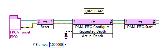
I have create a FIFO on the FPGA target (configured to Traget - to - Host DMA) and put the UINT16 5Million of a FPGA loop values, as soon as possible. Now, amazingly, I can read either with a VI on the chassis in real time, but also with an identical VI located on the PC host, even with similar performance.
In fact, I don't understand where the data are buffered and how the PC can access. I thoght the FIFO DMA memory needs to be on the RT target, right? So, how the data comes to the PC without a RT - VI? I guess that this method of data transfer (FPGA-to-PC) is not a use of FIFO, right?
In addition, when I check the property of "Possible elements" of FIFO in the PC - VI or RT - VI, I get numbers approximately 8000 to 10,000, while FIFO is configured with 1023 elements only.
How is that possible?
(Btw.: I realize that I'm losing a lot of data and the FIFO is small.) Yet, I want to first understand the points above).
The project is included in the ZIP.
Best regards and thanks for your efforts,
Joe
Hey Joe,
NEITHER offers a service called NI RIO Server. This service is installed with LabVIEW RealTime on your target in real time and allows you to connect to the FPGA of the cRIO/sbRIO from a computer.
I can't find a lot of information available on the internet, this page only:
How to make the devices to access RIO on a computer connected to the network? -National Instruments
http://digital.NI.com/public.nsf/allkb/43F81436B97AEE28862573D40069F440He is the Francis, why you are able to run the same program in real-time on the RIO and the development computer. It is also the reason why you must enter the IP address of the target in real time on the program running on the development PC. If you run the VI on the RealTime Taraget itself, it is not necessary to enter the IP address.
Some information on the size of the FIFO:
The FIFO is not only a buffer. A buffer of contains two FIFO.
A buffer is located in the FPGA itself. It is unbelievable small (1023 elements by default), but this buffer is super fast. The size of this buffer is configured as part of the LabVIEW project. You can increase the number of elements in the buffer zone, but you will never be able to achieve an elements > 20K buffer size due to the constrained resource of the FPGA.
The second buffer is located on the site in real time of the RIO. This buffer can be bigger than the buffer on the FPGA, usually 10 x or more. You can configure the size of the buffer of site in real time by your LabVIEW Code on the part in real time.
Best regards, Stephan
-
RT FIFO only element Variable is always buffering...
First off the coast, I'm new to LabView and cRIO... Core 1, Core 2 and RT 1 filled online. No other experience.
I have a cRIO 9074 with some local IO also speak several Modbus TCP slave.
I was able to glean from my training for RT systems (NI unique priorities loops) shared vars that RT FIFO enabled. So in this case, the variable in question is...
I32
RT FIFO (single element)
Publication of the network (even if no Panel OR or other system - only uses for access through the Manager of distributed systems)
I see buffering in the cRIO and I don't know why it happens. And this is not desirable.
I was looking at the data of my ups on my HMI (two slaves ModbusTCP - neither produced NOR) and I unplugged the ethernet cable from the inverter - still the data on the screen was up to date always as if the inverter is connected. If the screen is buffering of data, or is the cRIO. To know which, I changed the configuration of the inverter slightly to get a pulse train in bit 0 value I32. Toggle so it 0/1. I then placed a door AND which would also add the train of pulses in a little more important so the tilting head count would then be 0/16385. I could then manipulate the gate AND the ups to send 0/1 or 0/16385 in the cRIO at will.
I placed a probe on a variable that matches the entry of the UPS modbus in a vi that analyzes the modbus table in my variables.
I put a probe on the same variable (read access mode) who sends these data on-screen in a vi that packs vars in a table to send the wire of the HMI.When I changed the magnitude of the scale values, I noticed the entrance of the inverter replaced immediately, while the output of the HMI remained on the old values (always switch) - and finally (the number of seconds later) replaced with new values. More the application runs... more the delay before the variable HMI takes on the current values of the inverter.
This variable is FIFO RT single item, published network. And if I understood correctly, FIFO variables NOT only element buffer values. So if they are being extracted from a queue is more slow as they are added (or not taken at all in this cae)... the current value should replace just the value queued.
FYI: The behavior is the same with local o - I probed a thermocoule entry from one module 9213 which is also sent to the GUI and it is buffered as well.
Also, I tried to uncheck the RT FIFO on the variable in question and saw no improvement.
Any help to understand this behaviour and a way to eliminate it would be greatly appreciated...
No, in the beginning I have not.
I tried some experimenting with it enabled and the size defined for an element.
In the end, it seems to be a result of failing me to UN-deploy and redeploy the libraries containing the variables in question. (problem disappeared once I "wiped" the cRIO using MAX and re-installing the software load)
I was informed that the number of variables shared in my project, I would switch to a CVT according to method of distribution of the variables between the loops / process. So I will try which.
-
Data entry on the host VI without FIFO Massive?
Hi guys,.
First post on the boards and about two weeks in LV in time real/FPGA so be gentle!
I'm data capture of a system using a CRio 9082 and Converter A/D NI9215. The FPGA vi runs a timed loop (10 US or 100kS/s) that pulls in the data and sends them to a target-to-Host DMA FIFO (4096 long, single precision). Since I want to synchronize data for a TTL output, the FPGA also sends a True/False value through a port DIO (NI9402). So, for example, if I want a TTL of 100 Hz pulse and time of the loop is 10 US, then a complete cycle of TTL will last 1000 loops with the half cycle lasts 500 loops. Both the position in the LIFE cycle (0-1000) and the acquired data to that position in the cycle are intertwined in the FIFO. I have attached a picture of the VI.
The host vi simply reads the values of the FIFO, decimating the interlaced output and stores the data in a table for later processing. I have also attached a picture of the host vi. The problem is that the data acquisition time could be as high as 10 seconds, which would mean that the FIFO host-side would be long 2 million items!
SO my question is how to change the host vi so that rather than wait as the FIFO side host to be filled, its size can be reduced and yet not lose data points in the table fill? One can rightly wonder why I did things like that, but I found that fill a massive FIFO ensures that I do not lose the continuous position TTL data, but then I thought it was totally ineffective and some sage advice is necessary!
Thank you!!
My advice would be to do the following:
(1) configure FIFO depth to be quite large not to overflow during a regular operation, but don't try to configure it to keep your entire dataset in a single shot.
(2) If you send only the integers to the FIFO, do not configure it for double rooms.
(3) instead of voting for a whole dataset, you can read the smaller packets of the target and build them together on the host. Pop, a delay in your in a loop to read each 10/100 ms, 0 items via a FIFO Read, out of the remaining elements of wireless node to the number of items in a FIFO read node entry. It will take all that is in the FIFO at this stage. Using a registry to offset, concatenate the table with table of the previous iteration and stop all loop when the length of the array reaches the number wanted items.
You might need to play to ensure that the order of the data in the FIFO is not flipped depending on when you start and stop acquisition, but at least it's a start.
-
Disable the extended FIFO FPGA target during execution
Hello
I use a FIFO extended target in my FPGA to constantly calculate the derivative of a measured value (dB/dt). Thus the FIFO stores all values during time dt. This means dt determines the number of items in the FIFO and dB is determined by the actual value less the oldest value in the FIFO. It works well when I initialize with the code in figure InitFIFO.
But the FIFO of compensation is not possible (see figure clearFIFO). In the while loop if "reset dB" is false, as the new value of B is written on the FIFO, then the oldest value is read from, for the number of items in the FIFO remain constant. To change dt during execution, I need to clear the FIFO and initialize it with a new length (number of items). I tried the next loop, but it does not work. The FIFO does not initilized with the elements. The length is zero and the loop counter for (#deltaB Length2) is 0.
What I am doing wrong? Is there a better way to erase a FIFO during execution in the FPGA? I'm now stuck for 2 days with this problem and looking forward to any idea or suggestion.
Thank you very much. Best regards
Andy
Hej,
Thank you for your response. You were correct, that deltab FIFO length was 0 because the defalt value was zero. The problem is that in my host vi on the RT system I put DeltaB FIFO length in a loop of high priority and as you can see when I restart the FPGA, DeltaB FIFO length has a valid value (the code in figure 1 works well with a local variable of DeltaB FIFO length in the FPGA). But the variable to set the variable "reset dB" is under the control of the loop of low priority of the host vi. And there, I had an entry DeltaB FIFO length unwired.
So, I learned that a control FPGA read/write unwired sends a '0' or resets the variable to its default value in the FPGA. I assumed that nothing is transferred and the last variable is retained if you let a control read/write unwired. Now, I learned of this stupid error!
Thanks a lot again!
Andy
-
Buffer FIFO output DAC on PCI-4461 and USB-4431
I remember correctly, there is a FIFO buffer on the output DAC of a PCI-4461 to approximately 2048 samples. Am I remembering correctly? What is the output DAC FIFO on the USB-4431?
Hi jmoses,
The FIFO on the 4461 is actually 1023 * samples (found in the page on record).
The 4431 does not actually list a FIFO size in the page on record, but any device that handles output clocked by material will have some sort of FIFO to avoid running out of data to generate. By using the Output.OnBrdBufferSize property node returns 4095 * samples - it is logical that FIFO would need to be bigger, given the higher latency of USB transfers. Unless you use on-board regeneration, the FIFO size should not typically be a concern since it is designed to be large enough to accommodate a continuous generation to the full rate of the device specced.
Action request corrective number 149512 filed with respect to the issue of the missing documentation on our USB DSA devices - I apologize for any inconvenience.
* If you are interested, the reason that the FIFO is not an even number of samples is the software limits the size of buffer to one less than the actual hardware buffer. This is necessary for us to be able to detect the difference between an empty FIFO and a State full of PEP (we use a reading and a pointer to write to manage the transfer of data in and out of the FIFO - we can say that the buffer is empty when the two pointers are equal and complete when the write pointer is a sample behind the reading pointer).
Best regards
John
-
Synchronization of FIFOs in FlexRIO SMU-7962R
I am acquiring data digitized using 16 channels NI 5751 on SMU-7962R. I have to do it as fast as possible that of why I use 4 FIFOs with depth of 32768 elements and width of 64 bits (each symbol takes 16 - bit).
I recently discovered that the FIFO is not synchronized. There is somehow arbitrary delays between different blocks of data from the FIFO. The delays remained the same, at the time of purchase. I think it is mainly due to the fact that I'm not rinsing the FIFOs correctly during the initiation.
Is it possible that I can solve this it such that the FIFO is synchronized.
I enclose the folder of the project, also the charts for Host.vi and FPGA.vi
Any help will be very appreciated!
Appreciate the feedback!
Your previous post made me understand that it is indeed possible to increase the depth of the FIFO on the host side (I have 12 GB of RAM, IE I have virtually no limits). This allowed me to redevelop the FPGAS such as I now use a simple FIFO instead of four to communicate with the host (only running at 10 MHz instead of 50 MHz sampler, also helped, because I had need of 5 ticks to serialize data).
So, the problem is solved using a simple FIFO instead of four. Thank you Christian for pointing me to finger the right directon.
-
How to turn RT FIFO on a shared variable for custom control
I try to get my shared variables behave: update when I tell them of and only update once. It's the sort of 2 separate problems. Update only once should be fixed by activating RT FIFO on the shared variable. However, if you create a shared variable by using a custom control (because your data type is not available on the menu drop-down), allowing RT FIFO is not available. Why is this? Will there be an another GUARANTEED way to do this?
Description of my goal: after having many problems with a large scale of my real-time program version, I started from scratch. My program is that the bases in order to send a signal to my goal of running on a few D/A channels, then return the data that I read A/D channels to ensure that the waveform has the same appearance. In addition, the program should be able to repeat this process without having to reboot.
-Host is a state machine with: initialize - reset variable, check that the UI events - start target, target stop and end program, send data - to create 2 waveforms and send it to the target using the variable "data entry" (table 2D-double), data Get shared - read the entire waveform on the different channels after it ran using the shared variable "all data output" (table 2D-double) , Write to the file - (does nothing), stop - program ends.
-Target is a loop with 2 States inside: false - target does nothing as he waits to be the host to say 'Start', True - target Gets the shared variable input data, runs on 2 D/A channels and reads the equivalent A/D channels to make sure the waveform actually ran as expected. This happens in a deterministic loop with a non-deterministic loop waiting for the command "Stop" on the host. After the written entry, the D/A signals stop and playback of signals/a. are placed in a 2D array and sent to the host via a variable shared, "all the output data".
-J' tried to put "all the data output" in a while loop which must reiterate if he does not obtain data in the specified time-out period. I also removed the while loop but kept the specified time-out period. In both cases, data are collected twice!
-Without specifying a time-out, the host never gets data updates "all output data" before he goes into another State.
Summary: I need update they once when I asked to a my shared variables. I think that my program is about as simple as you can get, so I'm surprised to see why he is currently not completely reliable.
(I have attached the vi host, target the vi and variable)
Hi FireIce,
To answer your questions:
1 RT FIFOs are supported data types can be pre-allocated space. This is to keep the determinism on the RT system.
2. reading of the variable in the loop and have the chart outside the while loop will only show the last value of the shared variable, showing actually only a single reading. Then if it works for you, it will give the same result.
Looks like you have network buffering enabled on your shared variables. Is this true? Shared variables must always have a value, and so it will continue to contain old data to the new data is written to it. If you have buffering enabled network, new data can be added after the former, which actually look like you read the old data twice before getting the new.
-
MAX does not see the cRIO modules!
Hello
I have a cRIO-9073 and C 3 (9401, 9239, 9263) modules installed in slots 1-3 respectivly. I can configure the chassis correctly upon arrival 2 months ago and I managed to acquire by a module 9234. Now that the 3 mentioned c modules arrived I installed and have a problem - MAX of nothingness, or analysis of LabVIEW RT engine cannot see modules. Attached are MAX.png and DiscoveryStatus.png that depict. NOR-RIO is version 4.00 and corresponding set is completely downloaded to the cRIO. I do not understand the concept of software cRIO yet but I'm positive, that is the same as used to work the first time that I had tried. The network is OK - host is 100.0.0.1, cRIO is 100.0.0.100 and they see.
I susspected that perhaps specific drivers are needed for these particular C failet, but I can't verify that the status of software.
Basic details to accept and understand the CompactRIO concept is spread across many different documents, and it's really hard for the newbees to grasp, so debug/fix situations.
Does anyone have an idea what is causing my problem?
Thanks in advance,
-
Fortunately the cRIO merger two time real screws: analog and digital output
Howdy,
I need help with a cRIO code. The purpose of the code is to acquire an analog input from the NI 9234 c series module and be able to send a "signal of pulse" digital camera (first low for some time, t1, then high for some time, t2) from a NI9401. Separately, I wrote the code to perform both tasks. However, when I add the code of RT digital output pulse pulses to analog input RT code, the DMA FIFO overflows because of the way that my digital pulse output code works. Currently, there are two reasons which overflows of the FIFO:
- The digital output code is pending for a while loop (pending "Send Pulse" become a true), the loop I can't empty the buffer FIFO
- The FIFO is not enough, quickly emptied depending on how long the pulse (t1 and t2) times are. The way I keep the pin high or low for a defined period of time is by issuing a sleep command, which blocks the loop I empty the FIFO. (Is there a "best" way to sleep?)
I have attached photos of my codes FPGA and RT. Please give me a suggestion on how to marry my two loops of RT for the use of happy resources! Thank you.
I found a quick way to solve this problem. I moved the timing of the Digital pulse on the FPGA. So whenever I have a Boolean value, the FPGA generates a waveform with the settings I put (a pulse in my case). This works because the FPGA loops run in parallel, I think. That's why, when I run a pending order in the loop of FPGA digital output, it does not prevent the FPGA of analog input loop to run. I have attached a picture of the code.
-
Hello
Can someone tell me how to access the serial port of the crio 9024. I pass the data to the serial port of the controller. This transmission must be by crio serial port and not by module CSeries.
Thank you
Hello mimran,.
cRIO controllers run LabVIEW Real-time. Therefore, you perform series read/write through the range of NI-VISA in LabVIEW. All data collected from the port, or sent to the port will have to be given "String".
There are examples for reading installed with LabVIEW series. These are only a few small changes to work as in real time.
Follow these steps for an example:
- Launch LabVIEW.
- In the main menu, go to the 'Help'-> 'find examples '.
- In the upper left corner, click on the tab "search".
- Search for the term "series".
- Open the example called "basic series write and Read.vi.
Kind regards
-
cRIO-9024 - supports SSH (Secure Shell) network?
The Shell Server enable secure (sshd) in the measurement software & automation for the cRIO-9024 OR is not available. Usually, this would be an option as shown here:
http://www.NI.com/white-paper/14626/en/
The cRIO-9024 OR does support SSH? Do I need to install anything extra on the target? I installed most of the software on the web on the cRIO.
Thank you
Mitch
N ° only targets Linux (in the current line cRIO, i.e. the x 906 and 903 x) support ssh.
-
All,
I have a cRIO-9068 I try to use the scan mode for. I have intalled all the latest drivers and software as explained. However, when I put my chassis to scan mode, then select deployment all, I get this error on my chassis and all my modules:
"The current module settings require a NI Scan Engine support on the controller. You can use Measurement & Automation Explorer (MAX) to install a software package recommended NOR-Rio with NI Scan Engine support on the controller. If you installed LabVIEW FPGA, you can use this module with LabVIEW FPGA by adding an element of FPGA target under the chassis and drag and drop the module on the FPGA target element. »
Everyone knows this or know why labVIEW does not recognize that the software is installed on my cRIO or is it not installed correctly?
AGJ,
Thanks for the image. I saw a green arrown beside all my pictures of chip and it seemed that meant that the software wasn't really being installed. I formatted my cRIO and did a custom install. My problem was that I had the two labview 2013 and 2014 installed and the cRIO put conflicting versions of software. After doing a custom installation and choose only the versions of 2014, my picture now looks like yours!
Maybe you are looking for
-
How to stop the Sync tab? When Open firefox it opens also tab asking to sign up for synchronization.
When click on browser Firefoxon to open it now add check automatically on every time that compatibility, never used to do this. Just started doing this because on Firefox starts, it opens a designated Home tab and another for Firefox sync join to the
-
A custom step of multiple digital limit test | Hide the limit tab
Hi all I am trying to create a custom step of multiple digital limit test. The custom step by itself poplulates the value of the limits of the measure. So I plan on Hide tab limits within the parameters of the step. Can someone guide me on how to do
-
Hi all QuickSpecs:I have a Lenovo T61p here type 6457.It is the one with the Quadro FX 570 M videocard.I installed it with Windows 7 Ultimate 32 bit and Windows XP Pro SP3 32 Bit All latest drivers have been completely installed, DirectX 9 June .0c a
-
connect windows 8 con mac? Como lo hago
quiero pasar archivos desde mi mi pc mac don't con windows 8 pero no be como hacerlo! porfavor ayudenme
-
the display windows were smaller and don't return to normal size
After that my laptop turns off after have overheated, I restarted to find the width of my screen has decreased about one inch on both sides and the duration has decreased about a cm upstairs and downstairs. I tried to reboot several times, but the si