DaNI ultrasonic sensor
Dear all
I work with robot of DaNI, I have problem with the PING sensor which turns 90 degrees to the right instead of 180 degrees (from right to left)
can someone show me the possible solutions?
https://www.YouTube.com/watch?v=xUKOZTjYubk
Thanks in advance
When you install the actuator for ultrasonic sensor, make sure that you can move it by hand all the way to the left and to the right. The engine has only a range of motion of a bit more than 180 degrees, so if you don't align the sensor in the center of the range of motion it will not move correctly. Also, be sure to run the VI utility that calibrates the offset of the engine angle once you did.
Tags: NI Software
Similar Questions
-
Is it possible to store data until you get to the next required target ultrasonic sensor?
Hello
I have an ultrasonic proximity sensor used to control a weeding. I use the sensor to detect the differences in plant height. Plants weeds and crops, I would essentially like to eliminate weeds and avoid harm to crops by the device. Crops are higher than the weeds, so I use LabVIEW with 1208FS USB DAQ to compare the different heights. My sensor is located in front of the camera in about 20 inches. When he starts playing the first plant (weed) the unit will act immediately and kill. When he arrives at the second factory (culture), the device will be on the first plant which means jump some weeds like the sensor to read harvest. This way I can kill crops and weeds or ignore the weeds. Is it possible to store or delay data from the sensor until the device of weeding out get to the required target? Thank you!
-
help in the programming of the ultrasonic sensor Hc-sr04
Hi im new in labview, I must connect the sensor SR04 HC to the SensorDAQ ultrasound and I have to measure the distance between the sensor and an objetc, I made a small program but the distance is very erratic and I saw an example but I have not underestand the code in the example, so I don't know how to change it to do what I need later today, I'll put the vi, I did and I found, my code is very short and the code I got terrible long.
If my program is bad, can you tellme where and why? or isn't the code as the sensor requieres it please tell me.
If the example I add the code I really need can you explain all the parts and how to change it in order to work with the sensordaq.
Can you tell me how to connect the sensor to the sensor data acquisition? so you can help me, I'll add my photos and connection diagram.
I do a sensor of reservoir with this sensor data, and order a motor with it, if the level is below 20% use the Stairmaster to open a valve, is his scratching that nearly 80% the stepper.
Another thing I need is when the level of the reservoir is scratching at 80% another mottor, steper no must be turned on and should work for a specified time. When this time is on a signal of "empty tank" should be displayed.
I think is a lot of what I need, I plugged the stepper mottor (bipolar motor 4 son) and I do can work, I don't know how to operate in both directions, so I have to solve this problem.
I will add photos and my screws later today, Please helpme, the most important thing is to make the sensor to work.
THANKS FOR THE HELP.
-
Hello
I'm working on Dani 1.1 robot with sbRIO. How can I add/connect another sensor it and test it. Its a sensor to ultrasound (LV - EZ1 maxsonar).
Help, please.
ConcerningHi Danish666,
What kind of bus the ultrasonic sensor work by?
The sbRIO using, there are options of communication via protocols such as wireless. If the sensor uses TCP/IP or UDP to send and receive data, then it should be possible to write a driver for LabVIEW RT to talk to the probe. The complexity and involved, this driver may need to be will depend on the sensor.
As the sbRIO works on real, should also check the compatibility between the sbRIO and time any sensor that you are wanting to plug in as drivers may have been designed for a windows OS. If it is compatible, then we can discover options such as communication to him through VISA controls.
I look forward to hear your responses.
Kind regards
-
Measure the distance using color sensor 2.0
Hi all!
I would like to know if there is a way to measure the distance of an object using the color sensor that comes with the Mindstorms 2.0. I am gaining a few conferences of the sensor, but I don't know how to convert these values to distance.
Any reference or a link would be appreciated!
Thank you!
Hi fran_jo,
Here is an article which offers a good method to calculate the exact values of scaling to convert measures of intensity at a distance: http://www.hitechnic.com/blog/eopd-sensor/eopd-how-to-measure-distance/. Do not forget that this relates to a third party of sensor, but the concepts should always be applied.
Also note that the color sensor is affected by ambient light. You can try to use a 2nd sensor to take account of all the ambient light. What you trying to accomplish with this application? Is there a reason that you are not using the ultrasonic sensor?
-
With the help of cRIO-9073 with 9403 module and Ping sensor
I try to have a Ping of Parallax))) to work with my cRIO ultrasonic sensor. I have connected it to an e/s digital 9403 module and uses the PulseGen, SW.vi example. I plugged in and configured the 0 for an output pin have significance attatched on the output pin to monitor output. When I put the pulse width to be something less than 10 ms long and I try it is not always release trigger and when that happens it's always long to 10ms. is there a way to reduce this sort I get a pulse of what 5?
Hi digilogik,
You can post how you have changed the code, so we have a better understanding of what to expect. Brief looking at the example code I couldn't guess why a long 10 ms pulse is the only thing you see if what you did was replace the power indicator 0 with IO nodes.
However, if your end goal is to get a pulse of 5 usec, then the NI 9403 module will not respond to your needs as the updated module is 7usec max. You would be able to do what you need with a NI 9401 module, with the draw back you go to 32 channels up to 8 with the 9401 vs the 9403.
Bassett Hound
-
How create/get ColorPal driver for LabVIEW?
Hello!
I am a french student in England and I'm working on the Starter Kit 2.0 (with DaNI Robot). My company wants to turn the feature of prevention of obstacle (thanks to the ultrasonic sensor) into a follower of colored (thanks to the Parallax ColorPal) line. So I want to program in LabVIEW but I don't really know how to get the driver ColorPal or screws to connect between the sbRIO 9632 and this color sensor. I use the same yarn as the ultrasonic sensor to connect the ColorPal.
Thanks in advance for your help.
Concerning
Kevin
Hey Kevin,
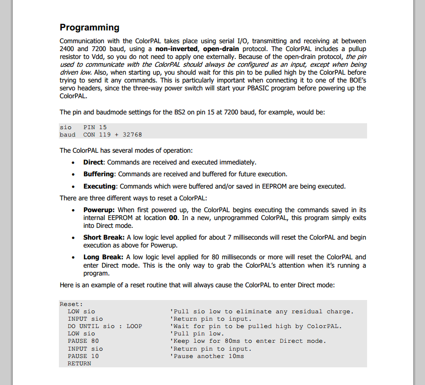
I took a glance at the ColorPal documentation and it seems that it is programmed using e/s series. As you can see below:
You will need to do, is use series found below the palette of e/s of instrument LabVIEW VISA and functions to communicate with your ColorPal. I recommend that you download their website ColorPal documentation and study the syntax of the commands that you will need.
Also for reference here is a good place to start when programming of VISA.
Kind regards
-
Median filter isn't removing the spikes at the bottom
Hi all
I use a median filter to spikes of deletes for the acquisition of data in real time of thickness of an ultrasonic sensor. This filter works great to remove the upper tips, unfortunately the bottom spikes remains unchanged. I tried changing different grade in the median filter with no improvement.
Attached images are code LabView and graphs showing data before and after filtering. How can I remove these spikes at bottom also?
Thanks in advance
Apple
I think that your problem is your acquisition code, not the filter. The data set, you have posted has 969 items with values of 2.681 or 2.68. The other 54 elements have values as 2.6, 681, 1, 2, 8 and 68. An element has the value 5, and there the value 9.
What this suggests to me, it's that your VISA reading is not correctly synchronized with the data transmission device. Either you get partial messages or an occasional character that does not match your regular expression. Look at the default value stored in the reading string in your VI. Unplug the display of ' \' character mode. It contains '\D5U=\F32.681\r\n2.681\r\n2.681\r\n' it looks like there two characters special \D5 and \F3 and then three values separated by carriage return, line feed. With this kind of protocol you should probably use the jump as a default line end character. Then search for the string \D2...\F2 which can be a header or channel ID. The rest is digital data.
Check with the creator of the device that sends data to determine the complete communication protocol.
Lynn
-
Hexadecimal string to numeric value
Hello
I have a really (I think) a fundamental problem of trying to convert between a hexadecimal number to a 'digital constant' value so I can calculate certain things.
The situation is: I'm able, a VISA series, a distance of an ultrasonic sensor reading. His current reading in an "indicator of string" ordinary put to a hexadecimal display. About 50 cm from distance with the ultrasonic at a wall sensor, I can measure "0032" as my display hex - what is optimal, 32 in hexadecimal is 50.
However, my problem is, how do I now go to the conversion of this 0032 in hexadecimal in a usable digital/decimal numbers?
Thanks heaps for you help.
Nick.
Typecaset 2 bytes of string to U16, for example as follows:

-
I use LabVIEW2010 for the width of pulse measurements (duration of the pulse). using DAQ PCI-6052E. This is my program!
But my no good result! Help me!
My sensor is the SRF05 ultrasonic sensor
my result is not good, because I received the result but if large (very large) can be over 400 s
I don't know why?
-
Filter for table data, the range of data obtained and defined 2D
I produce data of an ultrasonic sensor at 1 K Hz, and there is a lot of data (data points range of 0 to 10). However, in some cases when I know that the data should be about 7 (for example) I get outliers (about 9 and 10). Is it possible to define a filter for data in the defined range.
I averaged the data to get an average value, and outliers are distorting. In the worst case, my outliers are 30 to 40% of the data generated. I created a filter to sort the data and, taken from the lowest value. I stop the loop when data reaches a value greater then 9. But this seems to take a long time (because the loop checks for each data point and there are 1000s of them).
Is there a better way to filter data and define a predefined table range to collect?
I enclose my filter.vi... and a set of samples of my previous data. The ranges of data of 10-8 and would like to have the range 7.5 to 8.5 to consider. The sensor records tension here and the problem can be solved by installing a different type of sensor, but if a filter in LabView can due it, the sensor that we use now is absolute.
I am in kind of emergency, my design in unfinished because of this problem, if someone can find some time to share some suggestions, I will be grateful.
Thanks in advance.
See attachment. I have incorporated the data you've posted in the vi. It doesn't seem like any data were less than 8.7 or so, so I modified the scope so it would be a few points on average. Some games were completely out of reach while the average came back like NaN (not a number) due to a division by zero.
-
I'm looking for a time sound real when system starts in a PDA?
Hi all!
I want to create a program that can be useful as a meter away. I have the PDA with microphone and speaker, so I can use it as sonar in the audible range.
The problem is when I try to find the point in time when my acoustic impulse starts ringing. It is very important to know the exact time of the impulse starts as it affects the quality of recognition reflected pulse.
If I use special functions such as 'Get System Time' or 'Ms timer value' I usually get incorrect results.
First my program starts to save, and then after the start of the pulse of 100 ms, then after 200 ms program will stop recording and saves the data.
I get RecStartTime, SndStartTime, so I can calculate how many data points in my record are before Pulse: (SndStartTime - RecStartTime) * 44, 1.
But I always find start impulse in my test folder much later.
So I don't think that "Mrs. timer value" can be used to know exactly the moment of time of sound starts (really starts).
How can I avoid this problem?
Thank you.
I'm not really sure that a Microphone and a speaker are sufficiently precise a method to measure the distance. Perhaps you should consider a hobby ultrasonic sensor. I used a lot of these things in College and it worked very well.
-
Dear all,
I am doing the project for my final year on Panel engineering front hovercraft using labview. Here, I have attached my vi. Please someone go through it.
I get a series entry and display temperature display thermometer. Problem is as soon as the series executed and displayed reading the temperature on the thermometer the thermometer displplay display goes back to 0, reading, it will not always see the result.
suggestions needed,
I need to set up the sensor right, left and right, which is the Ultrasonic sensors which is the present enemy near the sensor and I need dispalay the distance between the sensor and the enemy who also came from Sanchez helps labview.how to implent it.
Please someone help me to do this work.
Thank you and best regards,
Sudarshan
LabVIEW, the default 'resets' orders or the default value (zero) indicator.
The reason why you have to put your code inside a loop is very intuitive and a knowledge of the "common sense". You must specify the computer to keep your program execution for a specified period or until you force quit. If you don't do this, your machine runs each statement once and then, period. Imagine a plane that runs a control post (the brain) code within a material, without a loop. It will run once (for a period of a few microseconds) and then your aircraft will have no brain to decide what to do. So it will crash. Millions of lives will be lost.
The loops are necessary 'energy' to keep your active code for a while. Your code will run once, and after it is finished running, its controls and indicators back to their State natural quantity ZERO.
Maybe it's one of the reasons for your problem. Try putting a WHILE LOOP with a FALSE Boolean constant hung with terminal condition. Or simply wire a Boolean control the State OFF. If there still is no temperature reading, or get the reading as you mentioned, then there must be a problem with the acquisition hardware that you are using to measure the temperature.
Try to put the loop first, observe and come back here.
An other logistics major, that you need to take care is the SUBJECT LINE. Do not mention the title of the project in which you are facing problems. You are the door problem on only a part of your overall design. Try to get to issue brief, to-the-point. For example I have a robot (General design) where I get no ultrasonic sensor data (a design offer) because Calendar and the sycnhronization is a little new to me in LabVIEW FPGA (under part of part of overall design). So my subject line would be Timing and Synchronzation ultrasonic sensor in LabVIEW FPGA.
Kind regards
-
LabVIEW FPGA and real-time communication module
Hi all
I created a small program in labview FPGA which gets continually distance from the HC - SR04 ultrasonic sensor. The rest of the robot program is written in the time module real Labview. Is it possible that the distance calculated by FPGA module to read in time real module.
I used the FPGA just because there micro-deuxieme counter, which helps me get the distance from the ultrasonic sensor.
Thanks in advance.
There are many ways this can be done, according to your needs.
See the help article transfer of data between the FPGA and host (Module FPGA) for a breakdown of each method.
-
How to interface a sensor with IO-Link
Does anyone have experience interface LabView with IO-Link? I have a remote sensor that can be apparently programmed using IO-Link, but information on the IO-Link bus is rather sparse. I would be very happy if someone could share their experience/advice.
Hi Dan,.
Sorry, we do not have a simpler solution. I would like to know if you find a way to go on this.
Maybe you are looking for
-
10.3.6 using I have a DVD with the video, I want to put it on my iMac, and then burn another DVD. I external drive and note that there are many "burn" command and the copy command, in the Finder, that they do not seem to work. How to burn a DVD with
-
Hi guys,. I have a Toshiba Satellite Pro 4600 PIII900/128 / 20G / 14 t/D/LM/W (it is written on the sticker under the portable) MODEL No.. PS460E-04NVW which MoBo should I do? Mine is broken, so I want to buy one on eBay, but I don't know what model
-
5681 calendar view to 'reach '.
I do turn into some unusual problems, understand the time to sample the 5681 scope mode. aid is of great help. Thus, a few quick questions, assuming a capture internally triggered 300mS RF burst with a portico at 50 to 250 ms is desired using 200 sam
-
HP Pavilion 15 n208-tx restarts repeatedly after updated recent windows 8
My laptop automatically installed the recent update of windows 8 at shutdown. After that, it is not start properly. It restarts several times only. A whole summer facing the similar problem. Please suggest.
-
Good memory RAM for Aspire 5736Z-4460?
I'm looking to find good memory DDR3 RAM for an Aspire 5736z-4460. I bought it used and am unsure of what the PC3 - 12800 s is correct. I don't know that it is PC3 or DDR3. Thank you!