Data NOR 6561: 36 MHz clocked
Hello
I need to send/receive the LVDS data from/to a product. Data must be clocked at 36 MHz and the clock will have in the product.
Can you confirm that if I use a PCI-6561:
-J' I need a 36 MHz external clock, connected to the jack IN CLK (clock edge can't be used?)
-I have to export the sample clock on one of the CLK OUT ports
Thanks for your help,
Anne
Hi Anne,.
You're right on all points. The 6561 can only generate frequencies from 200 MHz/N with its clock on board. You might get 40 MHz or 33.3 MHz, but not of 36 MHz. You can connect a 36 MHz clock source to CLKIN and use it as your sample clock source. You can also export this clock with your data (if you use the DDC clock on terminals, data and clock will be a guaranteed phase relationship).
Hope that helps,
Keith Shapiro
National Instruments R & D
Tags: NI Hardware
Similar Questions
-
USB-7856R shows a 40 MHz clock...
Hello
We are looking to buy a USB-7856R to start prototyping with FPGA technology for future projects. I've been playing with the FPGA examples in LabVIEW. I created a simulated for the USB-7856R FPGA target. When the target is implemented in my project, he mentions a clock of 40 MHz in the target.
Why is this? The 7856R USB is spec'd with a 80 MHz clock.
The FPGA has a base of 40 MHz clock. The OID can be clocked to 80 MHz. You can make a clock derived from 80 MHz to 40 MHz clock.
-
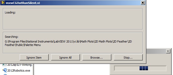
Acquisition of data NOR usb 6008: a strange problem: mxwcgoutrunsilent.VI is not respected
Expensive OR
Today, I bought an acquisition of data NOR usb 6008
and I'm using labview in 2011
the problem is appear when after I end the process of configuration of the i/o data acquisition Wizardthe following image shows the mxwcgoutrunsilent.VI is ignored and an error has occurred
someone can help provide this VI for me
What is the complete labview modules can also so I could do a real time data acquisition
Best regards
mangood,
You received an error code? If so, what is it? What version of NOR-DAQmx driver you have installed? It seems your driver potentially incorrectly installed, and you may need to reinstall the driver.
Here is the link to the latest version of the NOR-DAQmx driver: http://www.ni.com/download/ni-daqmx-9.8/4297/en/
-
Independent of the 40 MHz clock Onboard FPGA PPS GPS meter
Could you give me some advice or point me in the right direction?
I need to time counter accurate/tick synchronized by GPS PPS synchronization signal.
I got cRIO S.E.A. GPS Module that trigger PPS signal at the bottom of basket FPGA. PPS rising edge signal precisely mark the beginning of the second.
When I measure the number of ticks of 40 MHz clock FPGA embedded in a (PPS) second number of ticks is not 40.000.000 ticks but something like 39,999,800 ticks.
I want to measure with precision time between edges up/down digital signals. Because the clock of 40 MHz FPGA are drifting I can't use it.
How could set up my own witch counter ticks will be put away with signal GPS PPS?
I don't expect that I could provide 40 MHz FPGA on board the oscillator.
Should I create my own counter which will increase the opposite by the value 1.000,005 (40 000 000 / 39,999,800) each tick and this counter will be running timed loop (chronometric 40 MHz FPGA embedded base). Increment the value (1,000...) will be updated every seconds dependent PPS vs FPGA clock drift.
My configuration: cRIO-9025, cRIO-9116, S.E.A. GPS + cRIO module, high-speed DIs NI 9402, RT/FPGA LabVIEW 2011
Looking forward to your hearing you.
PeterHi all
This could help you.
Timekeeper FPGA
- http://digital.NI.com/public.nsf/allkb/EFDC35727D4F2CC086257A0700693003
- https://decibel.NI.com/content/projects/NI-TimeSync-FPGA-timekeeper
(I do not understand how this could be released on 23/05/2012)
-
precision microsecond using 40 mhz clock
Hello
The time between the 2 following loops deference should be 1 micro second. I have 40 mhz clock and its derivatives. How can we achieve this. ?
Thank you
Rognard
Sorry, there is an error.
Assuming that the analog input range is +-10V:
Scale-10V, 0 (16 bit binary)
and 10V as 65536 (2 ^ 16 last value in the range of 16-bit)
Take care to complete the sign (since its signed integer) bit when moving - 10V-1, then 0 to 10V
-
"Data was overwritten before it can be read by the system" count with PCI 6601 with 20 MHz clock
Hello Aditi
What exactly is the purpose of the use of the clock of 20 MHz? You count the edges of it?
You can try to use the VI DAQmx Configure entry 'buffer' to increase the size of your buffer. You can also use the DAQmx channel node to set the DMA data transfer mechanism. If you create a channel node, you can get to this specific property through this path: counter of entry: general properties: learn more: Advanced
 ata transfer and memoryata transfer good mechanism.
 -
Satellite Pro 6100: Intel Pentium 4 M clocked 0.2 Mhz instead of 1.8 MhZ clock speed
Hello
I have a 6100 Pro Satellite under XP SP2 on Bios 1.90. A few days ago, he suddenly started running very slowly.
According to the value of the ID of Intel, processor running at approximately 0.2 MHz, instead of the maximum speed of 1.8 MHz, with a similar reduction in the speed of the bus.
I have reset the BIOS and restore the MBR & OS, but the problem remains.I'm running on current alternative, with display 100% charged battery. I also turned off all power settings to try to stop the running slow robot through the Intel speedstep technology.
This might sound like a hardware problem, but if I boot the machine from a Linux CD (Knoppix), it works very well - very reactive, and according to linux, the clock measures the speed to about 1.79 MHz.
Does anyone has an idea what could be causing this, or what I can try next?
Hello
at first your machine cannot operate at 0.2 Mhz. It's impossible! So I think that this utility Intel ID is not give you correct information. He must know that the slower speed will achieve your cpu, established in the region of 600 mhz.
With 0.2 Mhz run your computer won´t!
You said that you have restored your system, but the fact that you have installed the latest drivers and tools for this computer from the Web from Toshiba site?Maybe your CPU is defective, which can be a reason.
Welcome them
-
How to use the I2C clock as 1 MHz clock source?
I use USB-8452 and try to find the source of the clock that allows to generate 1 MHz.
Hi JimSi,
You try to make it to the USB-8452 generate a constant 1 MHz signal? If so, I don't think that you will be able to do it, sorry.
Best,
-
Hello
I use the card PCI-6111.
I am trying to acquire analog data on channels dev1/ai0 ai1/dev1 using pulses of external clock connected to the PFI0 channel. I also want to trigger the acquisition, when the channel dev1/ai1 signal reaches certain level. I send a triangle wave channel dev1/ai1, and I need the data only for the front.
I have configured the task in the following ways:


However, I get the error-89137 after function DAQmx Start Task:
Specified route can not be satisfied, because it requires resources that are currently in use by another route.
Source device: Dev1
Terminal of source: PFI0InputLockOut
Target unit: Dev1
Destination terminal: AnalogComparisonEventResources in use by
Task name: _unnamedTask
Source device: Dev1
Terminal of source: PFI0
Target unit: Dev1
Destination terminal: AI/SampleClockTask name: _unnamedTask
If I change the internal clock external clock - switch works. If I pull the trigger, the external clock works, too. But these two tasks do not work together.
Help? Advice? Thank you!
-
Simultaneous to the AO and HAVE with the acquisition of data NOR USB 6001/MATLAB Toolbox
I am very new to data acquisition and bought a NI USB 6001 to start to learn. Because I can get free MATLAB through my University, I use Matlab data acquisition Toolkit as the data acquisition software.
My problem is that I get the following error message when I try to generate an AO (an LED voltage) signal and measure a signal I (voltage of a battery of 9V) simultaneously.
ATTENTION: This change is caused in the dump output data queue. Use queueOutputData for the queue data before the start of the object.
Hardware does not support the specified connection. Check the user manual of the device for the valid device routes and pinout.However to measure IA or by generating the AO each by themselves works perfectly well.
My Matlab script looks like this:
daq.getDevices;
s = DAQ.createSession ('or');
s.Rate = 1000;
s.DurationInSeconds = 10;
addAnalogInputChannel (s, 'Dev1', 'ai0', 'Voltage');
addAnalogOutputChannel (s, 'Dev1', 'ao0', 'Voltage');
aoVoltage = 1.8 + 0.1 * sin (linspace (0, 2 * pi, 10000))';
queueOutputData (s, aoVoltage);
s
startBackground (s);
Note that adding the channels HAVE and AO at the session also works, however I get the error mentioned at the start of the session. This is a limitation of my data acquisition hardware (I don't see something like that mentioned in the manual) or do I have to modify the script?
The pins connected for the LED are AO0 (+) and AO GND (-).
The pins connected to the battery are AI0 (+) and (-) AI4. (The problem is still there if I use the reference to the ground for AI)
6001 cannot make simultaneous tasks. Very standard limitation of the low-end hardware... just don't have on board computing resources to handle such things. Even the 621 x boards have only limited multitasking abilities.
Can intensify to a high range data acquisition ($$$) or buy a 2nd a low end and synchronize tasks in software (not as precise calendar). I've done two approaches, one is "best" really depends on demand... If low-cost or high-performance is a priority.
-
ACQUISITION OF DATA NOR USB-6251
is it possible for the box USB-6251 to provide an output for a test set-up during playback of the inputs of the device even? for example: 10VAC Ridge to Ridge on the luminaire, mixed the sine and square wave signals of the luminaire to the data acquisition Toolbox.
Yes. The 6251 has two outputs analog and 16 analog inputs. Open finder example and looking for examples of both. Under input and output hardware > DAQmx > Syncronization > multifunctional, it is an example of analog inputs/outputs synched.
-
My acquisition of data NOR usb-6008, does not appear in labview after installing drivers
My DAQ does not appear in my labview program after installing the drivers. I can't add it to my program or anything like that. I installed 3 different drivers and updates, and it's still not appearing in labview. Is there something I'm missing or need to do yet?
Thank you
It seems that you have a damaged file somewhere in your installation. You will need to go into the control panel and select the option to repair the installation. You will need to run the repair twice due to a known problem. After that, you need to reinstall the NI_Daqmx 9.4.
Jacob K
-
Acquisition of data NOR-9205 Assistant set up range of input voltage
How to configure the module NI9205 to use the +/-200mV input range.
I use a custom scale, and it seems that I can not get an accurate reading. I use a shunt current of 100 Ma (max 10A). So I custom balance setting to have 100 x + b. The current flowing in the device is 2 amps and I get a reading of 12-13 amps after custom scale. Now I think the module is configured to sample for the entrance of 10V and I get an error of resolution.
Hi therbert
Since your custom scale is 100 x, to work on the beach of +/-200 mV to your NI 9205 module you must configure your input signal of maximum and minimum range for +/-20 respectively.
According to the equation: Range.max * scale.slope = 200mV * 100 = 20V
This will automatically configure to the scope of the module +/-200 mV to verify you can access the channel DAQmx property node and look for the analog input > General Properties > advanced > Range property, this will let you know in what range is the functioning of the device.
Concerning
-
NI-DAQ-200288 digital output error
Hi all
I am using Matlab control PCI-6534. In the code, I try to write not Npulse (= 3). Pulse. Data of the pulse are of size 1 X 1e5. When I try to write in the mode of generation of finite samples it generates error-200288 when you write data pulse 3rd time. 1 twice, it gives no error.
The flow of code below is 1. Open 32-bit channel to write digital data to the 10 MHz clock.
2. put sample over genration and disabel regeneration.
3 write first pulse data to buffer.
4. start the task
5 enter the number of data pulse Npulse-1 immediately
6. wait until the task is done and stop the task
CLC;
inputDATA = uint32 (100 * randn(1,1e5));
NPulse = 3;
rate = 1e7; % 10 MHzIf (libisloaded ('myni') ~ = 1).
[notfound warnings] = loadlibrary ('nicaiu.dll', 'C:\Program Files\National Instruments\NI-DAQ\DAQmx ANSI C Dev\include\NIDAQmx.h','alias','myni');
end
taskh = libpointer('voidPtrPtr',0);
DOtaskhandle = taskh;
[errCode, taskName, DOtaskhandle] = calllib ('myni', 'DAQmxCreateTask', ", DOtaskhandle);
DOtaskhandle.setdatatype ('voidPtrPtr');DAQmx_Val_ChanForAllLines = int32 (1);
DAQmx_Val_Rising = int32 (10280);
DAQmx_Val_GroupByChannel = uint32 (0);DAQmx_Val_FiniteSamps = int32 (10178);
DAQmx_Val_GroupByChannel = uint32 (0);
DAQmx_Val_DoNotAllowRegen = int32 (10158);
numSampsPerChannelWritten = libpointer('int32Ptr',0);
reserved = libpointer ('uint32Ptr', []);
data2 = libpointer ('uint32Ptr', inputDATA);
sampsPerChanToWrite = uint64 (numel (inputDATA));
inDataLen = uint32 (numel (inputDATA));
sperchan = uint32 (inDataLen);[errCode, lineNames, nameoflines] = calllib ('myni', 'DAQmxCreateDOChan', DOtaskhandle, [' Dev1/port3 Dev1/port1, port2/Dev1, Dev1/port0], ", DAQmx_Val_ChanForAllLines);
[errCode, clockType] is calllib('myni','DAQmxCfgSampClkTiming',DOtaskhandle,'OnboardClock',rate,DAQmx_Val_Rising,DAQmx_Val_FiniteSamps,sampsPerChanToWrite);
If (errCode ~ = 0)
errMessage = "Error during clock setting";
calllib ('myni', 'DAQmxStopTask', DOtaskhandle);
calllib ('myni', 'DAQmxClearTask', DOtaskhandle);
return;
end
[errCode] is calllib ('myni', 'DAQmxSetWriteRegenMode', DOtaskhandle, DAQmx_Val_DoNotAllowRegen);.[errCode, writeArray, numSampsPerChan, zz] = calllib ('myni', 'DAQmxWriteDigitalU32', DOtaskhandle, sperchan, 0, double (10), DAQmx_Val_GroupByChannel, data2, numSampsPerChannelWritten, reserved);
If (errCode ~ = 0)
errMessage = "Error when writing the data of Stimulation" 1;
calllib ('myni', 'DAQmxStopTask', DOtaskhandle);
calllib ('myni', 'DAQmxClearTask', DOtaskhandle);
DISP (errMessage);
return;
end[errCode] = calllib ('myni', 'DAQmxStartTask', DOtaskhandle);
if(errCode~=0)
errMessage is ('error in startup DAQmx task');.
calllib ('myni', 'DAQmxStopTask', DOtaskhandle);
calllib ('myni', 'DAQmxClearTask', DOtaskhandle);
DISP (errMessage);
return;
end
for i = 1:NPulse - 1
[errCode, writeArray, numSampsPerChan, zz] = calllib ('myni', 'DAQmxWriteDigitalU32', DOtaskhandle, sperchan, 0, double (10), DAQmx_Val_GroupByChannel, data2, numSampsPerChannelWritten, reserved);
% If (errCode ~ = 0)
% errMessage = "Error when writing the data of Stimulation";
% calllib ('myni', 'DAQmxStopTask', DOtaskhandle);
% calllib ('myni', 'DAQmxClearTask', DOtaskhandle);
disp (errMessage);
% return;
end %
endIstaskDone = libpointer ('voidPtr', logical (0));
[A11 A21 A31] is calllib ('myni', 'DAQmxIsTaskDone', DOtaskhandle, IstaskDone);.while(A31==false)
[A11 A21 A31] is calllib ('myni', 'DAQmxIsTaskDone', DOtaskhandle, IstaskDone);.
endcalllib ('myni', 'DAQmxStopTask', DOtaskhandle);
calllib ('myni', 'DAQmxClearTask', DOtaskhandle);Can anyone help me please with this code. Is there some step I'm missing or not setting any parameter not?
Thank you
Vani
Take a look at this:
Why do I get error-200288?
http://digital.NI.com/public.nsf/allkb/BFCE83133C0ECAD786256E6000814B68?OpenDocument
Using traditional DAQ or DAQmx?
-
problems in real-time with 6534
Hello
in our application, we use a PXI-6534 card to acquire datas. With 20 MHz, we acquired 32 bit data. We have several applications that work without problems. But now on the current project we have problem and we don't know why.
When we create test signals and read them in the 6534 we have several failures, which means bits that are not read correctly. Because we have 3.3 volt signals and the 6534 is a 5V card, it was expected that the problem is there. But now we think that it may also be that we broke the real time.
Parameters:
-Data entry
-20 MHz clock frequency
-32-bit
Does anyone know if the 6534 is able to acquire datas really up to 20 MHz?
Thanks in advance
Oliver
Hi Marco,.
During this time, we did an independent test.
We have created an independent generator that sent a test signal 3, 5V and 20, 8 MHz and 32-bit to thePXI6534 and checked if the data are complete. We discovered, that there is absolutely no data loss.
For us, this means that our problem is before the 6534 somewhere inside our electronics.
In general, this means that the 6534 can handle 3, 3V signals to 20 MHz.
Thanks for your help
Oliver
Maybe you are looking for
-
How to open or convert the .avi file on old mac running OS.10.6.8?
How to open or convert the .avi file on the old mac running OS.10.6.8. We tried downloading several conversion programs as well as programs that run .avi, but everyone's message could not be opened on the mac or require a fee. Anyone able to fix it
-
What details if it has to do with the tabs, I want that he gone or hidden permanently
-
Problem of overheating for Qosmio X 770 - 103 after installing Win 8
Recently updated my material with a series of samsung SSD 840 and installed windows 8 pro (64-bit) (due to business needs). After you have installed windows 8 I ran Wizard upgrade toshiba, to get the drivers that I needed, the I updated my nvidia 320
-
HP ENVY 15 - ae: second SSD on HDD1 slot in HP ENVY 15 - ae?
Hello I'm looking for a way to upgrade the SSD in a HP Envy 15 - ae. I opened it upward and the configuration is the following: -main 256Gb SSD PCIE Samsung -area empty HDD1 next to player of DVD, but no ferry and only a HDD1 connector empty on the m
-
When I try to go on line I get this runtime error prog c:\program files (x 86) \internet explorer\1 explore.exe. How can I fix it?