NI-DAQ-200288 digital output error
Hi all
I am using Matlab control PCI-6534. In the code, I try to write not Npulse (= 3). Pulse. Data of the pulse are of size 1 X 1e5. When I try to write in the mode of generation of finite samples it generates error-200288 when you write data pulse 3rd time. 1 twice, it gives no error.
The flow of code below is 1. Open 32-bit channel to write digital data to the 10 MHz clock.
2. put sample over genration and disabel regeneration.
3 write first pulse data to buffer.
4. start the task
5 enter the number of data pulse Npulse-1 immediately
6. wait until the task is done and stop the task
CLC;
inputDATA = uint32 (100 * randn(1,1e5));
NPulse = 3;
rate = 1e7; % 10 MHz
If (libisloaded ('myni') ~ = 1).
[notfound warnings] = loadlibrary ('nicaiu.dll', 'C:\Program Files\National Instruments\NI-DAQ\DAQmx ANSI C Dev\include\NIDAQmx.h','alias','myni');
end
taskh = libpointer('voidPtrPtr',0);
DOtaskhandle = taskh;
[errCode, taskName, DOtaskhandle] = calllib ('myni', 'DAQmxCreateTask', ", DOtaskhandle);
DOtaskhandle.setdatatype ('voidPtrPtr');
DAQmx_Val_ChanForAllLines = int32 (1);
DAQmx_Val_Rising = int32 (10280);
DAQmx_Val_GroupByChannel = uint32 (0);
DAQmx_Val_FiniteSamps = int32 (10178);
DAQmx_Val_GroupByChannel = uint32 (0);
DAQmx_Val_DoNotAllowRegen = int32 (10158);
numSampsPerChannelWritten = libpointer('int32Ptr',0);
reserved = libpointer ('uint32Ptr', []);
data2 = libpointer ('uint32Ptr', inputDATA);
sampsPerChanToWrite = uint64 (numel (inputDATA));
inDataLen = uint32 (numel (inputDATA));
sperchan = uint32 (inDataLen);
[errCode, lineNames, nameoflines] = calllib ('myni', 'DAQmxCreateDOChan', DOtaskhandle, [' Dev1/port3 Dev1/port1, port2/Dev1, Dev1/port0], ", DAQmx_Val_ChanForAllLines);
[errCode, clockType] is calllib('myni','DAQmxCfgSampClkTiming',DOtaskhandle,'OnboardClock',rate,DAQmx_Val_Rising,DAQmx_Val_FiniteSamps,sampsPerChanToWrite);
If (errCode ~ = 0)
errMessage = "Error during clock setting";
calllib ('myni', 'DAQmxStopTask', DOtaskhandle);
calllib ('myni', 'DAQmxClearTask', DOtaskhandle);
return;
end
[errCode] is calllib ('myni', 'DAQmxSetWriteRegenMode', DOtaskhandle, DAQmx_Val_DoNotAllowRegen);.
[errCode, writeArray, numSampsPerChan, zz] = calllib ('myni', 'DAQmxWriteDigitalU32', DOtaskhandle, sperchan, 0, double (10), DAQmx_Val_GroupByChannel, data2, numSampsPerChannelWritten, reserved);
If (errCode ~ = 0)
errMessage = "Error when writing the data of Stimulation" 1;
calllib ('myni', 'DAQmxStopTask', DOtaskhandle);
calllib ('myni', 'DAQmxClearTask', DOtaskhandle);
DISP (errMessage);
return;
end
[errCode] = calllib ('myni', 'DAQmxStartTask', DOtaskhandle);
if(errCode~=0)
errMessage is ('error in startup DAQmx task');.
calllib ('myni', 'DAQmxStopTask', DOtaskhandle);
calllib ('myni', 'DAQmxClearTask', DOtaskhandle);
DISP (errMessage);
return;
end
for i = 1:NPulse - 1
[errCode, writeArray, numSampsPerChan, zz] = calllib ('myni', 'DAQmxWriteDigitalU32', DOtaskhandle, sperchan, 0, double (10), DAQmx_Val_GroupByChannel, data2, numSampsPerChannelWritten, reserved);
% If (errCode ~ = 0)
% errMessage = "Error when writing the data of Stimulation";
% calllib ('myni', 'DAQmxStopTask', DOtaskhandle);
% calllib ('myni', 'DAQmxClearTask', DOtaskhandle);
disp (errMessage);
% return;
end %
end
IstaskDone = libpointer ('voidPtr', logical (0));
[A11 A21 A31] is calllib ('myni', 'DAQmxIsTaskDone', DOtaskhandle, IstaskDone);.
while(A31==false)
[A11 A21 A31] is calllib ('myni', 'DAQmxIsTaskDone', DOtaskhandle, IstaskDone);.
end
calllib ('myni', 'DAQmxStopTask', DOtaskhandle);
calllib ('myni', 'DAQmxClearTask', DOtaskhandle);
Can anyone help me please with this code. Is there some step I'm missing or not setting any parameter not?
Thank you
Vani
Take a look at this:
Why do I get error-200288?
http://digital.NI.com/public.nsf/allkb/BFCE83133C0ECAD786256E6000814B68?OpenDocument
Using traditional DAQ or DAQmx?
Tags: NI Hardware
Similar Questions
-
Hello
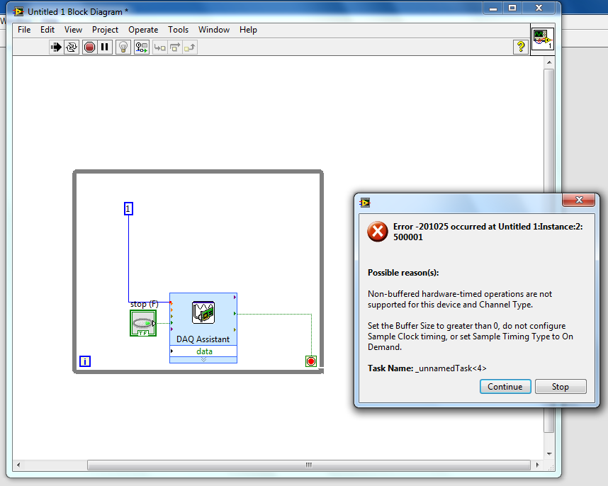
I'm playing with NI 9474 to learn how the outputs digital work with labview. However, I can't even the basic element down. I have a 9v battery connected to the unit and an element of resistance hung on one of the terminals of the device output. So, I just try to get labview to produce a digital output.
However, I get an error when I try to run the labview program. I tried to search my error on the knowledge base, but has been unable to find it. So if someone could help me understand how digital material output works with labview, it would be awesome!
I have attached my diagram!
Thank you
It's pretty basic. If you make an entry, you must specify the values to be written. For digital, values are true/false or 1/0.
-
Analog output PCI-6251-DAQ-200016 memory overflow error
NI PCI - 6251 DAQmx, AIMD-752 motherboard, dual core processor, a lot of speed and the ram running WinXP Pro & LabWindows/CVI
get DAQ-200016 memory overflow error when I try to generate a signal of analog output with a rate higher than about 32 000 samples/second (?)
going on what? I have never seen it before. Is this a problem with the motherboard? "It's the same product on the CVI code example" \Cont Gen Volt Wfm - Int Clk\ContGen - IntClk.cws.
If someone has had this problem, and is there a solution?
Thank you
PS: full text of the message reads:
Measurements: On-board memory precision passing. Due to the limitations of system and/or the bandwidth of the bus, the driver could not write data to the device fast enough to track the rate of output of the device. Reduce your sampling rate, change the method of transfer of data (from interruptions on DMA), use a product with more on-board memory or reduce the number of programs that your computer runs simultaneously. Task name: _unnamedTask<1> Code of State:-200016
Well, I found my answer. For later use, Olivia NI Apps Engineering suggested I have change the mechanism of data transfer by this Knowledge Base document:
http://digital.NI.com/public.nsf/WebSearch/C326F7D33CA6DB0E86256DFE008043B7?OpenDocument
... so I inserted the line of code between the creation of the area of OCCUPANCY of the channels and set up the example of clock calendar.
DAQmxCreateAOVoltageChan( ...

DAQmxSetAODataXferMech(TaskHandle,chan,DAQmx_Val_Interrupts);

DAQmxCfgSampClkTiming(...
now, I am able to generate output to a 2.35 MS/sec... max sampling frequency not quite the 2.86MS / sec indicated in the specification 6251, but close enough that I'll stop complaining

-
digital output without DAQ Assistant
Hello
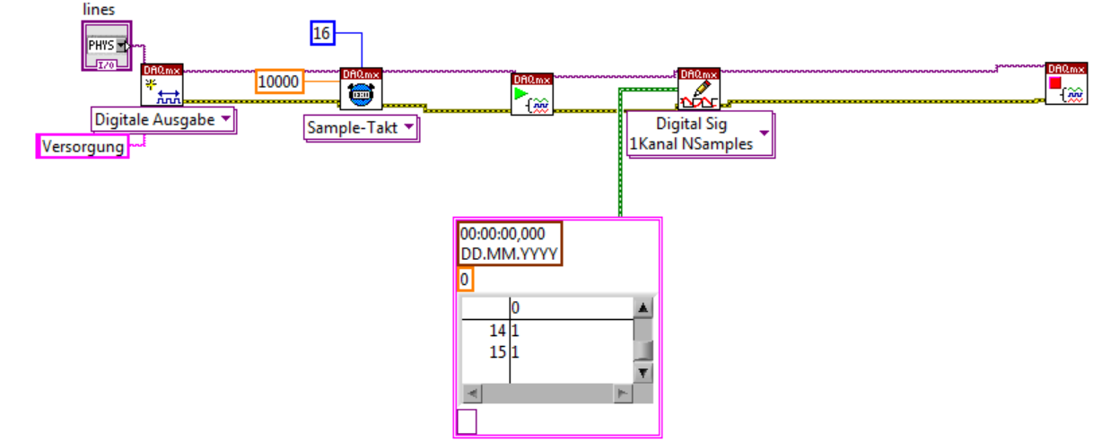
I can produce a digital output signal of some sampling rate 10 kHz with the acquisition of data-assist. Now I would like to implement the same functionality with normal DAQ - screw, as I have to synchronize serveral exits lateron. However, I failed get the normal screws so that they work as the DAQ assistant. The most important thing is out the arbitrary signal with 10 kHz.
Thank you.
Thank you very much. The idea of watching inside the acquisition of data-assist helped.
-
NEITHER 9205 digital output configuration with DAQ Assist
Hello
I have two NI 9205 Analog Input Modules which I have configured to read from each of their 32 channels. I used the DAQ Assistant help generate the vi which contains the task out - DAQmx event and also the DAQmx Read vi.
I used the Wizard twice, once for each module 9205 and then put the playback functions in a sequence structure so that only read would be carried out at the same time. It all works very well!
Now, I want to add in the code to wait in a loop before all loop containing playback functions, so that the user can press the GUI to send a logic 1 to the unit under test, and after it is sent immediately starts collecting data.
The DAQ Assistant Help does not recognize the module 9205 when I try to set up a task to write a digital output. 9205 a 1 digital output so why is the wizard does not recognize this? I also tried to create a task manually, but I got stuck.
Someone please help. I can reach the source if needed, but I thought that the descriptions above were sufficient.
Thank you
Gary
Hello
You are right it shows a line in this user manual, and in fact, you have found an instance where an important piece of information was left out of the documentation. This digital output line is actually only available when you use a cRIO chassis. It will not work with the chassis for the acquisition of data compact 9172. Here is a knowledge base that explains it. I'll also go ahead and file a request for corrective measures so that this note be included in the next version of this manual. Thanks for the comments.
Chris
-
6008 daq digital outputs to control relays
Hi all, I'm looking to help create a VI to send out digital to a daq 6008 to control relays. What I'm trying to do is when you press start and a condition is met send a digital output to control a relay for 30 seconds or so to take a measured voltage to be taken an analog voltage. After 30 seconds, I want the first relay to switch off and the next relay lights for the same amount of time. I want to continue this sequence to 7 readings, blood for every step and send the data to an excel file. I know it's basic stuff, but my experience with labview is limited! Any help would be greatly appreciated.
Thank you
Paul
Hi Paul,.
I looked on your problem this afternoon and I agree completely Fan Ravens that the state machine is in fact the most appropriate architecture for such a task of data acquisition. A state machine architecture is one of the most commonly used in LabVIEW design patterns and is especially suitable for any program where you have clearly defined the steps that can be represented by the States and rules for the transition between these States.
There is a model of Machine of State Standard contained in LabVIEW which should give you an idea of the underlying architecture and is a good starting point. To give you a better idea of how this architecture can be applied to a data acquisition task, I would recommend that you look at This example. Although States will be slightly different in your case, this should provide you with a good understanding of how you can architect such a request.
I hope this helps.
Best regards
Christian Hartshorne
Technical sales engineer
National Instruments UK
-
Maximum speed of digital output of the DAQ 6009
Hi all
I'm trying to generate a clock the digital output on my USB DAQ 6009 puse. The maximum frequency, that I was able to produce was 0.5 kHz, but I would like to generate at least 1 kHz. I HT wired port0/$line0 of the OID of data acquisition to the data acquisition ai0 and attempted to read the output via the input of an analog of the same device. I have attached the programs here. Don't know if it's right. You can help. Thanks in advance.
150 s/s is the maximum rate of the analog output. The 48kS/s is the maximum rate of the analog input. Read a little more closely.
This unit will not do what you want. I recommend putting the hand of your representative local of NOR and discuss your needs with them. They should be able to set you up.
-
How can I write a digital waveform to the digital output (traditional DAQ)
Hello
I use a NI 6023e, PCI, with 8 digital outputs. I generated a digital waveform. How can I write for a specific digital production line now?
I only have Labview 7, so I can't use DAQmx.
Thank you very much
-
How to quit smoking all the void s vi before resetting digital outputs and then closing
I have a project that contains a main VI called home screen that calls many different sub vi. I am monitoring for a press of physical button by a digital input with a DAQ Assistant on the main VI and in this case I want my program to abandon all of its VI running and reset all the digital outputs before the closure of Labview. No idea how I would go all this?
I have attatched the basic model of what I do.
Joelspider33 wrote:
The problem is more to do with some of my money that VI running a DAQ Assistant using the same digital lines like the ones I'm wanting to reset and causing it to throw up an error message.
This is why you must set the DIO AFTER all subVIs are arrested. And to do this, you must send messages to these subVIs telling them to stop. If done correctly, it is a very quick process.
-
digital output remain on inout end is off
Hello
I've been rattleing my head on this for the last two days with no luck.
What I try to do is the following:
Send a signal in a NI9421 Module, when the module receives this signal, it should exit on the NI 9472. These 2 steps I've completed and work however is the next part whicc I have problems with.
When the input signal is removed from NI9421 I would kepp receives a signal from the NI9472 for a period which can be easily adjusted.
I tried to highlight delays / waits (FOR loops behave as counters), while loops etc, but this doesis delays the time between entry Street to before the output turns on. for example. If I put in a 5 second delay, entry must be closed 5 seconds before the output turns on, and output will then stay on for another 5 dry.
Any help is very appreciated.
Thank you
John
Hi John,.
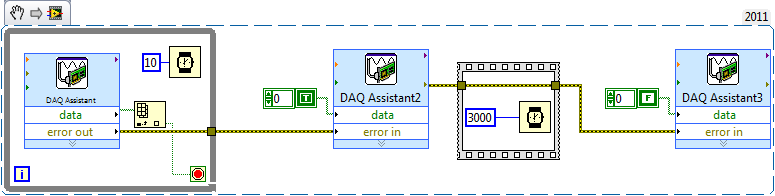
Take a look at the sample code below along with a description, if all goes well it will help you get started.
The while loop in the early polls pin digital input and a real wait to exit the loop and enter Assistant2 DAQ. The while loop in it has a wait of 10ms. This is to avoid it running fast and hogging all you time CPU. Since the output of the DAQ Assistant, in the while loop is a table, table VI Index allows to get a value that is wired in the loop condition.
The yellow lines used throughout of are lines of error and these can be very useful in LabVIEW to synchronize / order parts of your code. Following the order of the execution rule of in that the DAQ Assistant2 will not begin until all loop has finished running.
I then used a flat sequence order within 3 seconds (with error lines) between the second DAQ Assistant and the third that turns off the digital output.
Hope this is clear and useful
-
NOR-DAQ + NOR USB-4431: error 233054
Hello everyone,
First of all, here is my config:
-Dev PC: Win 7 32-bit
-LabView 2009 - 32-bit
- NI DAQ 9.7.5
-Card acquisition: NI USB-4431
The problem:
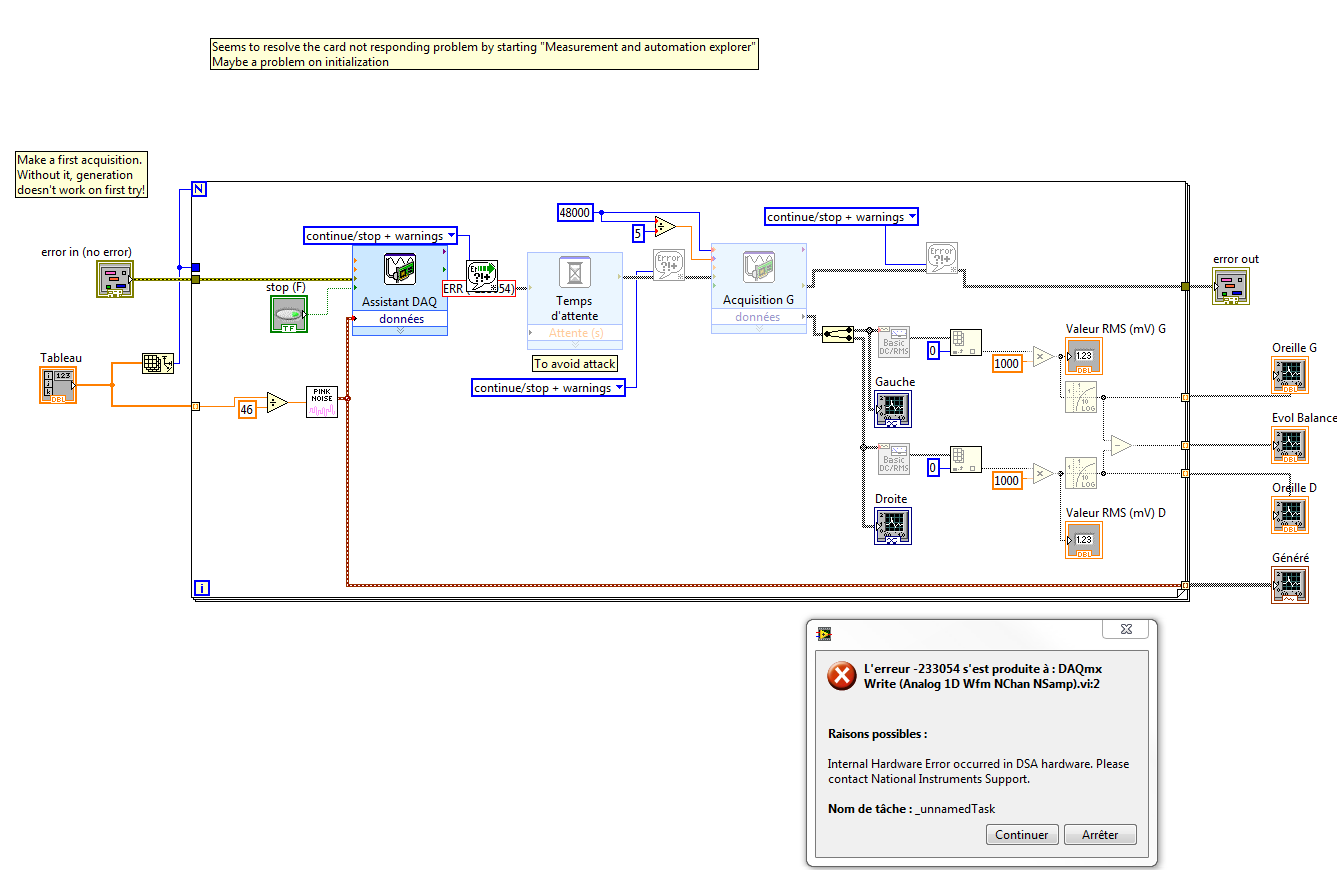
When I run my app just after connect my DVR to my PC (or after startup) card, the DAQ Assistant gives me error 233054:
I not found any explanation on this wonderful tool that is the internet, so I come here!

The only way I Born to move forward, is the NOT-MAX aperture, ask to make an acquisition, ask to do a generation (that work) and then I can go back in LabView and run my program!
The problem seems to come from the initialization. But I don't see what I need to do to make it work every time! Any idea?
Best regards
Harold
Hello
I just checked the daqmx and labview driver compatibility. I noticed your 9.7.5 daqmx driver version is not compatible with labview 2009, therefore, you have this agreement.
The latest version of LabVIEW 2009 daqmx is 9.7 see below
DAQmx and LabVIEW version compatibility:
http://digital.NI.com/public.nsf/allkb/B0D5630C0A50D5C6862578E800459248
So is this you can 9.7.5 uninstalling and reinstalling daqmx 9.7 see this link
Uninstall the software
http://digital.NI.com/public.nsf/allkb/AC6ED75D3D93375686256E8E00245F0D
Best regards.
-
take the digital output USB-6001 always high or low in c
Hi all
I am new to the NI DAQ interface. I have a USB-6001 and I am trying to use this device to control some flowchart in C. What I want to do is:
* set digital output lines with high and low intensity and change their status as needed (in C).
I tested the device NEITHER Max--> Test panels and found that the device is capable to do that. Then I try to do in C. I have checked hace examples and function I use is one called "DAQmxWriteDigitalU32". I have problem in the understanding of its input parameters. I tried something with my own knowledge, but it does not work as I expected. Here is a test I did:
data uInt32 = 1;
Int32 wrote;
TaskHandle taskHandle = 0;
DAQmxErrChk (DAQmxCreateTask("",&taskHandle));
DAQmxErrChk (DAQmxCreateDOChan (taskHandle, "Dev1/port0/line7", "", DAQmx_Val_ChanForAllLines));
DAQmxErrChk (DAQmxStartTask (taskHandle));
DAQmxErrChk (DAQmxWriteDigitalU32(taskHandle,1,1,10.0,DAQmx_Val_GroupByChannel,&data,&written,));taskHandle = 0;
DAQmxErrChk (DAQmxCreateTask("",&taskHandle));
DAQmxErrChk (DAQmxCreateDOChan (taskHandle, "Dev1/port0/$line0", "", DAQmx_Val_ChanForAllLines));
DAQmxErrChk (DAQmxStartTask (taskHandle));
DAQmxErrChk (DAQmxWriteDigitalU32(taskHandle,1,1,10.0,DAQmx_Val_GroupByChannel,&data,&written,));I just want to set ' Dev1/port0/line7' and ' Dev1/port0/$line0"at a high level, but only ' Dev1/port0/$line0' answer me. The second parameter of the DAQmxWriteDigitalU32 function is numSampsPerChan. If I replace (currently 1) with a higher value, such as 100, I see that "Dev1/port0/line7" sends a number of 1 output, then back to 0. So I guess that the problem is just that I understand not all parameters for the DAQmxWriteDigitalU32 function. Is someone can you please tell me how I can set up a line of digital output 1 or 0?
Thank you!
Hongkun
Hello
I finally find a way to do it! The feature works very well, and my problem was not set the data value to write correctly. It seems that if I want to write a 1 to the port0/line1, I put "data = 2 ^ 1" rather than "data = 1", because by default it is the second bit of the port.» Similarly, "data = 2 ^ 7 ' high level to port0/line7. I find that this setting is surprising when you want to control an individual line. It seems more reasonable when you control the whole port. In any case, is to solve the problem!
Thanks anyway!
Hongkun
-
separation of two edges using a digital output
I am using a DAQ, PXI-6229 map and programming in c# .net.
I'm claiming a falling edge on PFI12 used as a digital output, and I need to measure the time between this edge and a second front on PFI8 used as a digital input. I have implemented the code using some examples I found. I don't know when to to argue the signal on PFI12 in order to be read at the right time. Playback must be put in place before the signal is asserted, but I do not know how to set it up it up properly.
Here is the code I have so far:
Public Sub MeasureAcquisitionTime()
{
DigitalSingleInputTask = new Task();
CIChannel counterSetup;
firstEdge = CITwoEdgeSeparationFirstEdge.Falling;
secondEdge = CITwoEdgeSeparationSecondEdge.Rising;
Double minTime = 10-3;
Double maxTime = 60F-3;
String auxCounterInput = "/" + CardName + ' / PFI12 ';
String gateCounterInput = "/" + CardName + ' / PFI8 ';
counterSetup = DigitalSingleInputTask.CIChannels.CreateTwoEdgeSeparationChannel)
CardName + ' / ctr1 ', 'counter',
minTime,
maxTime,
firstEdge, secondEdge, CITwoEdgeSeparationUnits.Seconds);
counterSetup.TwoEdgeSeparationFirstTerminal = auxCounterInput;
counterSetup.TwoEdgeSeparationSecondTerminal = gateCounterInput;
DigitalSingleInputTask.Control (TaskAction.Verify);
runningDigitalTask = DigitalSingleInputTask;
counterInReader = new CounterReader (DigitalSingleInputTask.Stream);
Double data = counterInReader.ReadSingleSampleDouble ();
}I'm glad to hear it.
paofthree wrote:
Is there a way to make a measure of separation of two edges on the analog inputs of the PXI-6229?
The only way would be to constantly acquire the analog input voltage and calculate the separation of the two edges in the software.
Best regards
-
Hello
I am trying to learn labVIEW DAQ and right now I'm trying to understand how to use NI 9474 with labview. NEITHER 9474 is a device with digital outputs. I am attaching a (badly drawn) diagram of how I have my real wired circuit. For some reason, the voltage at the terminals of the resistance is 9v instead what that either the digital output should be when I put assistant daq for 1 sample on request. When I change to continuous samples daq assistant, it reads 4.6v. So I wonder what am I doing wrong and what should my digital output be?
I've attached my vi file, if someone can you please help me understand how to use NI 9474 with labview?
-
USB 6008 digital output signal
I am VERY new to LabView and have been racking my brain trying to get digital output of my USB-6008. All I want is to be able to get a signal of + 5 V of my digital output when I click on a button. This signal opens a valve on a system I see so when it is pressed, it must stay open until I press the new button. It seems simple enough to me, but I'm not too familiar with LabView. Help, please!
Stripling07
You must first take the LabVIEW tutorials and then look at the links to get started with DAQmx .
The simplest program would be with the DAQ Assistant. Drop it on your schema, and then select digital output > digital line. Select the line when the wizard has completed, click OK. Wire a Boolean value in a table to build and the output of which is connected to the data entry. That's all. You can test the output of MAX (Measurement & Automation Explorer) with the test Panel. Do NOT test with your connected tap. Your valve may require more current that can provide the 6008.


Maybe you are looking for
-
I can not install app purchased in ios 10
I can't uninstall an app purchase (no current app) in ios 10
-
Hello. Can you recommend add-one that can change or filter headers that send websites to my Firefox. Specifically, I want to ignore X-Frame-Origin. I'm doing this for my test purpose, so I don't care if Firefox displays the security warning or not.I
-
My old iphone 6s is completely broken, it does not or registry that it is connected when plugged into a computer. I'm able to recover photos from the SIM card with an adapter USB SIM card or through any other way? I also do not save anything with All
-
I would try Firefox, but Internet Explorer has to my work. If I download Firefox will I still be able to use IE? I have never used Firefox before and have heard a lot of positives about this and would like to try for myself!
-
Windows not genuine error message
Type of Korean computer installed windows on a new hard drive and it seems authentic, but I get the message that Windows is not genuine. I brought him two times and he refuses to do anything.