measurement of phase shift between two periodic signals acquired
Hello
I don't know how to explain my problem, but I'll give it my best shot. I'm two signals from sensors in tension. Two periodic signals have the same frequency, but a different amplitude. Normally they have a difference of phase of 0 or 180 degrees. The thing I have to let labview to check is if the signals are completely in phase or out of phase (180 degrees) completely. I am acquiring the wizard scene DAQ in a while loop. Does anyone have an idea how I can do this?
To summarize: are the two things I need to know
-l'amplitude (maybe just pick max max min distance)
-If both signals are moving in the same direction (when the two signals are in phase) or if they move in the opposite direction (counter phase) - the exact phase angle value is not so important
THX
Thanks for the reply. After a night to think about the problem, I came up with a home-made solution. I used the point by point max and min vi to calculate the distance from crest to crest of my signals. Then, I used the time derivative of point by point to calculate the variation of the signal of the two signals. If the signals are in phase (both are increasing or decreasing at the same time with the other), then the two derivatives have the same sign (accept on the summits, of which I have excluded from the comparison). If the signals are out of phase (when one increases, the other is decreases and vice versa) then the two derivatives are opposite in sign. According to this, I can get all information that I need. If anybody should know a better way to achieve the same result, please say, but to know that it seems to work.
Tags: NI Software
Similar Questions
-
variable phase shift between two analog output signals
Hey! I would drive two different piezo elements with an sine - / square signals and have a phase shifted output signals. After some trail and error, I was able to get a second analog output on my card PCI-6221 (using LabView 8.2) also allowed me to have different amplitudes for both signals. However, I could not output signal having a frequency different and most importantly to my request to have one of the signals variably shifted phase.
Thanks for the very useful suggestion. I have attached the file .vi installation I've run so far.
Hello!
A way to generate waveforms is using the analog waveform Toolbox. I created an example VI that is attached and that shows you a way to use the base generating function VI. I saved for LabVIEW 8.2.
I hope this helps!
-
Align the two signals and measure the Phase Shift
Hello
I do an experiment in which I use the NI USB-6221 DAQ card. The jury is able to make 250 k samples/second. I want to measure two voltages in a circuit and find the phase shift between them at frequencies between 1 and 10000. First I ouputted a wave sinusoidal frequency variable through the Commission and applied to a test circuit. Then I used the Board to measure the two tensions consecutively (thus reducing the maximum sampling frequency at 125 k). I used the signals align VI and measured the two phases and then calculates the phase shift (VI attached in Phase 1). It worked well for the test circuit I built in which the phase shift went way logarithmique.20 degrees ~84.5 degrees and then stabilized. At frequencies above 5 000 Hz phase shift must have remained constant, but it varies more or less 1 degree. When the phase shift is 84.5 degrees, present a degree of variability is not particularly explicit. When I asked my program on the circuit that I really wanted to measure, the phase shift went from-. 5 degrees up to about 1.2 degrees. The change in the values of phase shift at high frequencies (> 3000) was environ.2 degrees. Given the small phase shift, this variation is unacceptable. Now I tried to use a sequence to each blood individually (increase the maximum sampling frequency to 250 k) and then align the two signals and measure the phase of each shift. When I use align it and re - sample Express VI to realign the two signals, I get the message "error 20333 analysis: cannot align two waveforms with dt even if their samples are not clocked in phase." Is it possible to align two signals I describe here? I enclose the new VI as Phase 2
Matthew,
I think I have an idea for at least part of the problem.
I took your program data and deleted stuff DAQ. I have converted the Signal on the chart control and looked then what was going on with the signal analysis.
The output of the Waveforms.vi line has two waveforms, like the entry. However, arrays of Y in the two waveforms are empty! It does not generate an error. After some head scratching, reading the help files and try things out, that's what I think is happening: the time t0 two input signals are 1,031 seconds apart. Since the wavefoms contains 1,000 seconds of data, there is no overlap and may not align them.
I changed the t0 on two waveforms are the same, and it lines up. The number of items in the tables is reduced by one. Then I increased the t0 of 0.1 seconds on the first element. The output had both greater than the entry by dt t0 t0 and the size of the arrays was 224998. Reversing the t0 two elements shifts the phase in the opposite direction.
What that tells me, is that you can not reliably align two waveforms which do not overlap.
I suggest that you go to 2-channel data acquisition and that it accept the reduced sample rate. You won't get the resolution you want, but you should be able to tell if something important happens.
You may be able to improve the equivalent resolution by taking multiple steps with a slight phase shift. This is similar to the way that old oscilloscopes of sampling (analog) worked. Take a series of measures with the signal you are currently using. The make enough average to minimize changes due to noise. Then pass the phase of the signal of excitement to an amount that is smaller than the resolution of phase of sampling rate and repeat the measurements. Recall that I calculated that for a 5 kHz signal sampled at 125kHz, you get a sample every 14.4 degrees. If shift you the phase of 1 degree (to the point/mathematical simulation), you get a different set of samples for excitement. They are always separated by 14.4 degrees. Take another series of measures. Transfer phase another degree and repeat. As long as your sampling clocks are stable enough so that frequency does not drift significantly (and it shouldn't with your equipment), you should be able to get near resolution of what you need. The trade-off is that you need to perform more measurements and may need to keep track of the phase shifts between the various measures.
Lynn
-
Hello
Currently, we have two signals which are physically and logically linked together on the same line of data acquisition. The first, 'I' and the second signal, 'Q', are both related to "Ai6" (PIN 23) and "Ai GND" (Earth). However, when we probe the two lines coming our function "signal split", I drove Q by about 0.5ms. My question is, if these two lines are actually bound together physically and logically, then why are they phase shifted if they are both the same channel? They should be exact matches. I thought that the phase delay inter-channel occurs only in what concerns channels being read from data acquisition. I have attached a few screenshots as well.
Input signal is 20 kHz. Sampling rate is 40.5 kHz, number of samples/point is 1000.
Thank you.
Best,
Saami
System - Ultrawave Labs engineer
The board you are using is a multiplex. If you create several virtual channels, pointing to the same physical channel, we can enjoy this channel once for each channel. So what's happening essentially is that the physical channel was sampled once for channe 'I', then again for the channel 'Q' with a delay of a few milliseconds in between.
-
Synchronization between two periods loops FPGA
First of all, I appreciate the forums here and have read a lot of interesting topics. This is the first time I can't solve it with research and I hope for your entry.
Information:
I'm using LabVIEW 2009 f3, PXI-1033 with the PXI-7813R.
Problem:
In my FPGA program, I have two loops, where you need to run as fast as possible (has) and the second just quickly (B). Has turns 20 MHz to 40 MHz and B . These are for the two loops limiting speeds. B cannot run faster and Has should not run more slowly.
Loop has captures the sensory information and integrates data as many loops as indicated by the user. When completed, please send a trigger to B, which calculates the new position information and sends it to the machine. Only at certain times, B must achieve something and said nothing to the rest of the time.I thought of two ways, but doesn't work for me.
(i) with the help of a Boolean trigger. As in a loop, the Boolean value of A can become true and switches to the next loop to false, B is not capture all the triggers and a 50% chance of getting the triggers and isn't perfectly synchronized.
(II) using the occurrences. Sounds very interesting, but these are prohibited between the periods differently loops.
I played with many scenarios, but may not understand proper. Someone at - it suggestions?
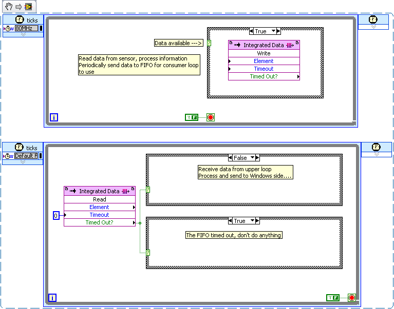
This seems to be a fairly simple producer/consumer scenario.
I would like to use a device worn FIFO to transfer data from the loop of producer (top) to the loop of consumer (bottom).
Depending on how often the producer generates data (each cycle or every nth cycle?) the case around the write FIFO structure will allow him to write only when your requirements are met.
The consumer loop reads the FIFO with a timeout of '0 '. When the FIFO is to expire, the consumer runs to the case which does nothing. When the FIFO does not expire, who processes the data and sends it to the side of Windows runs.
In my example, I used 2 structures of cases to illustrate the two different modes. In your code, you must use a single structure of matter.
There is no advantage to set a loop "sleep", even if no data exists on the FPGA. Because you are running in hardware and the non-profit CPU cycles these loops can operate simultaneously at no increase in the latency of a
-
Caculate phase difference between two sine waves
Hey guys
Im having problems with this. I read most of it-related topics, but none of the solutions posted helped me.
I have this small circuit and im taking a few values of voltage using my pc sound card. Data acquisition works well. As you may know, the sine wave read in Terminal resistance has a different phase compared to the dinna wave read to capacitor terminal. I tested the file VI and I can confirm it in the charts that I see out there.
I had trouble identifing the difference in phase (in degrees) between the two waves.
I would appreciate if you could help me with this. Here is my file of VI in case someone can give me some suggestions on how to calculate the difference of phase in degrees. Also, in this VI, there are some tests I did with no good result at all.
Any help will be appreciated
Hi moreins,
I changed the code, check it! I gave two solutions that somehow work to calculate the phase difference.
I would like to know if this solution works for you or not. Good day!
Sincerely,
Krisna Wisnu
-
I began to see the Skype to accept compatible streams recently and captured data using Wireshark. I see data sent to an IP address to my port 3619 and sent again to a different IP address. The packets have the same length inbound and outbound at about 16 Kbps. For example:
96022 543. [removed for privacy] 223.176.238.160 192.168.2.105 SKYPE 242 Audio Unk: 4
96023 543. [removed for privacy] 192.168.2.105 41.79.217.119 SKYPE 242 Audio Unk: 3
543 96024. [removed for privacy] 223.176.238.160 192.168.2.105 SKYPE 79 Audio
96025 543. [removed for privacy] 192.168.2.105 41.79.217.119 SKYPE 79 Unk Audio: 5
This is the hex data for the first two images:
0000 00 00 00 01 00 06 10 0d 7f 9B 00 08 00 08 00 a4...
0010 45 00 00 e2 46 25 00 00 2 c 11 b6 83 df ee b0 e. a0... F%..,.......
0020 c0 a8 02 69 05 77 0e 23 00 this f2 1 c fb 4 d f2... dc i.w. #... M.
0030 58 1 a 25 1 d 53 0d 36 cf a8 d4 37 10 9 X.% b2 f1 e5. ART.6. 7...
0040 ed a9 cb 8 9th e4 has e8 57 21 99 f6 9 b 83 71 7 c df... | W!... q
{[0050 65 5 d 7 d ca bd 2 c fe d2 25 b2 73 f3 4 d 9 a 39 8] e}..,... %. s.M.9.
0060 14 91 57 ca 35 of 8f 1f fc FC 29 34 2A e4 bc ba... W.5......). 4
{0070 62 34 21 90 85 8 c 6 93 7 b8 61 07 7 d d d be 25 ff b4!... l.}. a.}. %.
0080 73 d8 5A 07 73 70 b7 f7 f0 7 c 76 fd 9 d 1f 08 ee s.Z...s.p | v...
0090 ae c6 55 78 30 f2 1A dd 6 62 22 8f 1e eb b1 3f... "Ux0... nb"...?
00 a 0 2d 50 7f e1 dc 0e 4 c 13 31 df 89 7f 8f 1 d 5f 4F - P... L.. 1... _N
[00b 0 a7 0d fb a7 d4 3 a 20 d9 5 d 07 fe 58 68 2d... f5 d9:.] ... X.h.-
00C 0 ad 53 ef 6th 78 ea d1 d3 this 77 a7 1 d 29 4 9 c b2. S.n.x... w...) N
0 79 53 eb 97 00D 4 c 13 19 69 48 06 88 21 95 c6 yS e9 8f... L... i.H.. !...
84 24 9F 96 CBS 00e0 6th 1 d 41 69 3 c f7 46 fb 9 d e5 40. $... n... AI<>
00f0 d1 c6...and
0000 00 04 00 01 00 06 49 b3 3f e0 this 33 64 00 08 00... ? I have... 3D...
0010 45 00 00 e2 1f b7 40 00 40 11 54 7 c c0 a8 02 69 E... @. @. T |...
(29 0020 d9 of the 4f 77 0e 23 47 00 6f this 48 73 5f 3d f2 f8) O.w. #oG... HS. _ =.
0030 58 1 a 25 1 d 53 0d 36 cf a8 d4 37 10 9 X.% b2 f1 e5. ART.6. 7...
0040 ed a9 cb 8 9th e4 has e8 57 21 99 f6 9 b 83 71 7 c df... | W!... q
{[0050 65 5 d 7 d ca bd 2 c fe d2 25 b2 73 f3 4 d 9 a 39 8] e}..,... %. s.M.9.
0060 14 91 57 ca 35 of 8f 1f fc FC 29 34 2A e4 bc ba... W.5......). 4
{0070 62 34 21 90 85 8 c 6 93 7 b8 61 07 7 d d d be 25 ff b4!... l.}. a.}. %.
0080 73 d8 5A 07 73 70 b7 f7 f0 7 c 76 fd 9 d 1f 08 ee s.Z...s.p | v...
0090 ae c6 55 78 30 f2 1A dd 6 62 22 8f 1e eb b1 3f... "Ux0... nb"...?
00 a 0 2d 50 7f e1 dc 0e 4 c 13 31 df 89 7f 8f 1 d 5f 4F - P... L.. 1... _N
[00b 0 a7 0d fb a7 d4 3 a 20 d9 5 d 07 fe 58 68 2d... f5 d9:.] ... X.h.-
00C 0 ad 53 ef 6th 78 ea d1 d3 this 77 a7 1 d 29 4 9 c b2. S.n.x... w...) N
0 79 53 eb 97 00D 4 c 13 19 69 48 06 88 21 95 c6 yS e9 8f... L... i.H.. !...
84 24 9F 96 CBS 00e0 6th 1 d 41 69 3 c f7 46 fb 9 d e5 40. $... n... AI<>
00f0 d1 c6...Here's Skype data only on these images:
1 0000 c fb 4 d f2 58 1 a 25 1 d 53 0d 36 cf a8 f1 d4 e5... M.X.%. ART.6.
0010 37 10 9th ed a9 b2 9th e4 cb 8 has df 7 57 21 99 7 c e8... | W!
{[0020 9 b 83 71 and 5 d 65 f6 7 d ca bd 2 c fe d2 25 b2 73 f3... q] e}..,... per cent .s.
0030 4 d 9 a 39 8 14 91 57 ca 35 of 8f 1f fc FC 29 M9 ba... W.5......)
0040 bc 34 e4 2 a 62 34 21 90 85 8 c d 6 93 7 61 07 d b8. {* 4 b4!... l.}. one.
{0050 7 d be 25 ff 73 5A f0 f7 07 73 70 76 fd 7 c b7 d8}. %. s.Z...s.p | v.
0060 9 d 1f 08 ee ae 55 78 30 f2 1A dd 6 62 22 8f c6... "Ux0... nb.
0070 1st eb b1 3f 2d 50 7f e1 4 c 13 31 df 7f, 8f 0e dc? -P.... L.. 1...
0080 89 1 d 5f 4th a7 fb a7 d4 3 a 20 d9 5 d 07 fe 58 0d... _N.....: .].. X
0090 d9 68 f5 2d 53 ef ad 6 78 ea d1 d3 this 77 b2 9 c .h.-. S.n.x... w...
00 a 0 a7 1 d 29 4th 79 53 97 eb 13 19 69 48 e9 8f 4 c 06) NyS... L... i.H.
00b 0 88 21 95 c6 84 24 9F 96 CBS 6th 1 d 41 69 3 c f7 fb. ! ...$...n.. AI<>
0 46 40 d1 c6 F e5 9 d 00C... @..and
0000 f8 5f 3d f2 58 1 a 25 1 d 53 0d 36 cf a8 f1 d4 e5. _ =. X.%. ART.6.
0010 37 10 9th ed a9 b2 9th e4 cb 8 has df 7 57 21 99 7 c e8... | W!
{[0020 9 b 83 71 and 5 d 65 f6 7 d ca bd 2 c fe d2 25 b2 73 f3... q] e}..,... per cent .s.
0030 4 d 9 a 39 8 14 91 57 ca 35 of 8f 1f fc FC 29 M9 ba... W.5......)
0040 bc 34 e4 2 a 62 34 21 90 85 8 c d 6 93 7 61 07 d b8. {* 4 b4!... l.}. one.
{0050 7 d be 25 ff 73 5A f0 f7 07 73 70 76 fd 7 c b7 d8}. %. s.Z...s.p | v.
0060 9 d 1f 08 ee ae 55 78 30 f2 1A dd 6 62 22 8f c6... "Ux0... nb.
0070 1st eb b1 3f 2d 50 7f e1 4 c 13 31 df 7f, 8f 0e dc? -P.... L.. 1...
0080 89 1 d 5f 4th a7 fb a7 d4 3 a 20 d9 5 d 07 fe 58 0d... _N.....: .].. X
0090 d9 68 f5 2d 53 ef ad 6 78 ea d1 d3 this 77 b2 9 c .h.-. S.n.x... w...
00 a 0 a7 1 d 29 4th 79 53 97 eb 13 19 69 48 e9 8f 4 c 06) NyS... L... i.H.
00b 0 88 21 95 c6 84 24 9F 96 CBS 6th 1 d 41 69 3 c f7 fb. ! ...$...n.. AI<>
0 46 40 d1 c6 F e5 9 d 00C... @..I checked that these packages had been sent by the process of Skype. The change of IP addresses from time to time and sometimes it there streaming in all. I was not on any Skype call during this period. I have a file pcapng I can provide private these packages with over 200 k. I checked many of the IP addresses and found that all the ones I checked were on blacklists of some sort, so it may be the zombie PCs using Skype on other PC to transmit information or calls.
I use Skype 4.3.0.37 on Ubuntu 14.04 (updated). I checked the Skype updates, and he says I'm on the latest version. I tried to go through the process of reporting of security vulnerabilities and I had the choice to post here or wait for 20 minutes to chat with someone...
Please contact me directly. I make sure that my contact information on my Skype profile is up-to-date.
HTH
-Leo
I never said I could say what username was seen providing the past, I said that I could tell the IP addresses. That's all that is needed to find potentially vulnerable customers without the additional chore of scanning random IP.
In any case, I have already recommended that we spend our communication elsewhere. Is not not be able to control how traffic passed to third parties unsecured is a deal breaker for us.
Thank you very much for your answers. My question has been answered and my obviously concerns do not match that of Microsoft, so I end up in a dead end with this service.
-
How to measure the time elapsed between two steps?
Hello
In my script, I ask the subsequences. How can I measure the time it takes each subsequence?
Something like:
Statement: StationGlobals.TimeElapsed = 0
-> SOMETHING HERE TO START A COUNTER<>
call sous-suite
Popup: Str (TimeElapsed)
Thanks for help
StationGlobals.Time = Seconds()
... / / stuff in time
StationGlobals.Time = Seconds() - StationGlobals.Time
You can also view the sample report of basic step in 2012 TestStand time (you can now download an eval).
-
Meter with two adjustable phase shift
Hello
In this experimental device, I have a print head a TTL pulse-controlled piezoelectric ink jet delivering uniform droplets on a surface. I use the "time" version of the counter output vi (high-/ low-time) because it allows me to very easily change the characteristics of the droplets. I use a strobe approach for imaging the droplets as they are ejected. Basically, a strobe LED light is pulsed at a frequency that exactly matches that of the inkjet printhead. A CCD camera is used in order to imager droplets, who seem "frozen" on the screen due to the stroboscopic effect. Strobe LED is triggered by a train of pulses TTL (two pulse trains come from exits of meter on my USB-6353 X Series DAQ board).
Of course, I could trigger both the inkjet Printhead and the strobe light with the same output of counter, which would ensure that their frequencies match. But it's really nice to have a 'strobe delay' that allows adjustment of the phase shift between the strobe triggers and printhead. The hardware supplied with the print head has this feature of strobe delay as an external button. It is useful, because you can basically lead through time by turning the button and view the formation of droplets when it leaves the end of the nozzle.
I have a vi that may trigger sometimes the printhead and the flash, but I can't understand how to adjust a phase shift between the two, while the program is running. It should be possible, but I can't get it. I would really appreciate help with this. Attached is the draft code and a diagram which may help to explain what I want to do
Thank you very much
-Matt
No - forget the INITIAL DELAY. It's only for the (first) INITIAL pulse.
You already want to adjust the time / low-time already, no?
So having a new control called PHASE SHIFT, from scratch.
Have a variable called OFFSET PHASE CURRENT, from scratch.
When the PHASE SHIFT is modified (by the user), understand the difference between where he wants to be and where you are (control - PHASE CURRENT OFFSET) and add a lot of time the low TIMES, but only during a cycle. Basically you're stretching of a cycle. Store the new value in the course of PHASE SHIFT variable for next time.
-
phase shifted PWM with Ni 9401 and Crio
Hello
Do you have an idea of pwm shifted 180 degrees?
(duty cycle frequency and variable difficulty)
I tried a design, but it seems in the graphics design works on the realtime.vi but it does not work with the fpga.
Graphic output pwm FPGA are distinguished by the real time as you can see in the pictures.
On the other hand, VI Fpga produce two pwm, as seen in the oscilloscope when the fpga VI runs.
However, there is no phase shift between the PWM waves.
It is a part of my thesis, but I'm stuck in this problem, so I need assistance on your part.Thank you.
Best regards;
My hardware:
cRIO-9024 and cRIO-9118 chassis
NOR-9223, 9263 - nor, nor-9401, or-9474
two nor-9225 and nor-9227
Hi Maurice
Thank you for your help.
Yes I want to that they will be moved with the right variable and 10 kHz. I put 49% maximum duty.
I put the output into the same output block.
Square wave generator does not accept 'loop' while.
I have attached a simple FPGA project file. Could you please tell me what is my fault?
The resulting Pwm frequency is 10 kHz, the only problem is always the shifters.
So, I always need assistance.
-
Hello world!
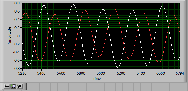
First of all, I use a USRP as a transmitter to emit a sine wave (the signal is exp(j2*pi*f*t)), and then I use the external clock to synchronize the two USRPs (Ref as PPS in are connected to the clock) as receivers. Receivers are in sync, and they are at the same distance from the transmitter, I thought that the signal they receive should have a nearly the same phase. However, in practice, the phase shift is big enough, and this problem really confuses me.
It's the received signals of 2 receivers.
Yes. What you observe is expected.
Near the bottof of this document read the area 'alignment Phase vs Phase coherence '.
http://www.NI.com/white-paper/14311/en/
And also, for the alignment phase, see the following 'Angle of arrival detection with NI USRP '.
https://decibel.NI.com/content/docs/doc-25716
Erik
-
determine the difference in phase between a reference signal and measure
Hello
I use a PXI-1000 b with two cards DAQ, PXI-6133 and I need to measure the difference in phase between a reference sinusoid, acquired on a map and an acquis of the sinusoid measured on the other card. So far, my idea is simply to acquire samples of N of these two signas as waveform data, then compare. My problem is that I see a way to extract the information from the relative phase. How would I do that? Is there a better way to achieve this end?
Hey GlenS
Check out this link. Use it a Subvi spend an entry as the data acquisition card entry and the other your reference wave. It should work.
Good luck

-laboratory
-
NEITHER 9215 delay in phase between two channels
Hello
I use Ni9215 with ENET-9163 to measure the phase between two sinusoidal incremental signals delay. First signal connected to AI0 and, secondly, to AI4 at 100 k sample rate. I know 9215 simultaneous ADC, but it seems to me that NI 9215 gives additional time between the channels. Is it possible, or l mistaken?Alexandr.
Hi Alexander,.
Please let us know how you get on,
Chris is correct - with the idea of using a right signal to both channels, I tried to suggest this earlier...
I hope this helps with your problems with delays,
-
Is it possible to route signals of relaxation between two chassis PXI-1002 with the PXI-8335?
Hello
as the subject says, I am interested in the delivery of a signal to trigger between two chassis PXI-1002. At present, these two chassis are connected by a MXI - 3 system using maps PXI-8335. The software is Labview 2010 sp1 and 380 NIScope drivers.
We want to keep (a PXI-5122 by chassis) scanners supply separated due to the requirements of our measure! The chassis are connected via cable to fiber optic. This explains why I can not just use the shutter release in Star, or connect via 'Trigger' or 'clk' cards (the inputs / outputs to the front of the cards).
I found a few examples, but they seem to all be designed for use with a chassis only, I'll call later to the examples that inspired me to this point. Each guide explaining the synchronization of several chassis systems seems to use another material or VI is not accesible to me. This makes me wonder if my hardware has the capacibilities I need.
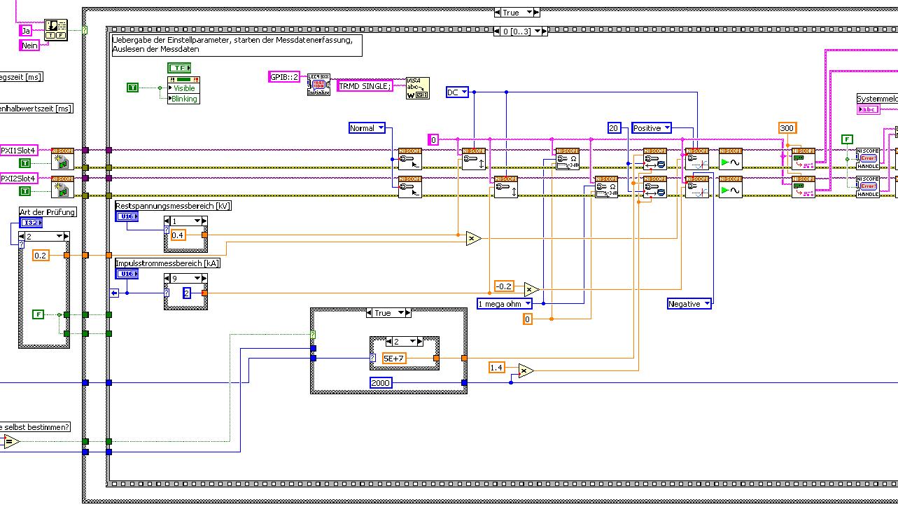
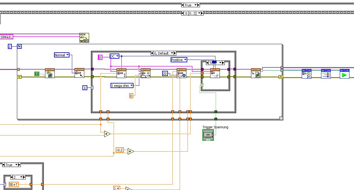
The first picture shows approximately where I started from (sorry I can't post VI, confidential...):
Only the middle part is interesting. Two sessions are initialized and manipulated parallel, trigger too. This has led to delays in the signals and should now be fixed. This apart from the VI works fine.
Goal is to trigger only on one channel but both devices! If possible, the device will trigger must be chooseable.
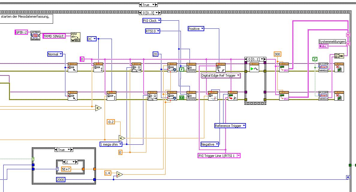
I started to rebuild the VI using the "EX Synchronization.vi 5xxx niScope' seeming spontaneity. The result is shown in the following image:
I tried different RTSI lines, but had no positive results. only the main channel has triggered.
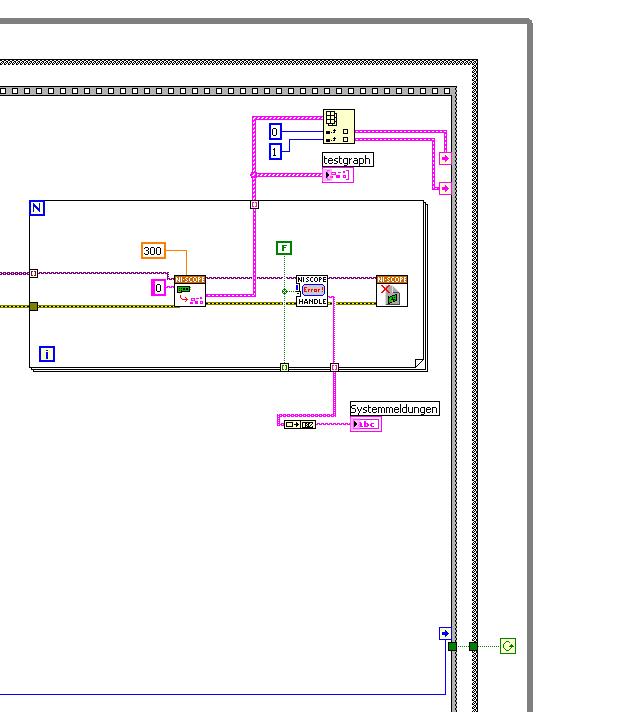
After this first approach, I looked in the "niScope EX .vi multi-Device configured Acquisition (TClk)" and other examples of TClk which seem to work for similar problems. The VI of reconstruction can be seen in the following images:
(Sorry, I had to use two photos..)
In this case, I didn't have no choice for trigger lines, it would automatically set the VI TClk. I tried to trigger on both devices, though. This second approach seemed promising to me, but it was an error:
"niTClk Synchronize.vi:1".
Index (starting at zero) of the session: 1
The error reported by the pilot of the instrument:
No registered trigger could be found between the
devices on the route.If you have a PXI chassis, the chassis correctly identify in
MAX and make sure that it has been configured correctly. If you use PCI
devices, make sure they are connected with a RTSI cable and that the cable RTSI
is saved to the MAX. Otherwise, make sure that there is an available trigger line
the trigger bus shared between devices.Source device: PXI1Slot4
Target unit: PXI2Slot4
Status code:-89125niTClk Synchronize.vi:1
Index (starting at zero) of the session: 1
The error reported by the pilot of the instrument:
No registered trigger could be found between the
devices on the route.If you have a PXI chassis, the chassis correctly identify in
MAX and make sure that it has been configured correctly. If you use PCI
devices, make sure they are connected with a RTSI cable and that the cable RTSI
is saved to the MAX. Otherwise, make sure that there is an available trigger line
the trigger bus shared between devices.Source device: PXI1Slot4
Target unit: PXI2Slot4
"Status code:-89125"
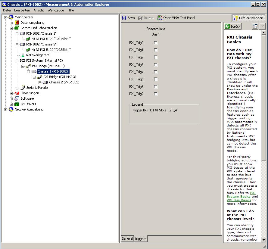
This error came back even after I've identified this drug as possible to the MAX, as shown in the screenshot:
In some of the textbooks, they showed how to get the MAX trigger lines, but as you can see, there is only booking options in my MAX. Whatever I do, I can't find options to define how to get my trigger signals...
In principle, it is possible to trigger instruments in different chassis, which is indicated in this Guide and others... the question that remains is can it be done with my set of components?
I understand that the use of multichassis compromised the integrity of the lines very adjusted as trigger in Star etc., so the configuration should be taken into account in some way, that my approach does not, I knew... But there must be a way to do this? And to start: to get just any signal from one device to the other trigger!
For any advice on this issue, I would be very thanfull!
Concerning
Max1744
Hi Max,.
Thanks for the detailed post and explanations of your application and requirements. You're right using TClk, because this is the optimal method to synchronize the 5122 digitizers. The original VI you worked with is unique for some of the legacy scanners and does not directly work with scanners based on the most recent CMS (for example the 5122). The good news is that you can synchronize these cards to separate chassis, but it will use the calendar 66xx and synchronization (T & S) cards in the chassis of the master and the slave, as indicated in the guide that you have accessed. These are needed because a common reference clock must be shared between them as well as a couple of tripping. MXI itself can not handle export triggers and clocks, so there is no way to do this without physically wiring between the chassis with cards T & S. Unfortunately, regardless of what specific method, you use for synchronization, it will take a material extra beyond what you currently have.
As one of your needs looks like it is necessary to retain wiring between the chassis directly, you may need to consider to synchronize using 1588 or GPS protocols. 1588 Protocol is a system for synchronization on the network while GPS course use antennas and locks for a common wireless signal. Although these synchronization methods may allow you to keep your chassis isolated, they will also require some manual configuration because you would be able to use the TClk synchronization and so the level of synchronization you can get between the cards may not be as good that can physically wire signals between the chassis using T & S cards.
Hope this helps,
-
Measure the time between two digital pulse
Hello
For a non-critical calendar application, I need to measure the time interval between consecutive TTL pulses, ranging from the order of 0.5 s for a few seconds, with a low accuracy of +/-10-50ms. The interval being measured varies between the rising edge of the first pulse and the front of the next and so on.
I have several input lines I need to deal with. Because it's a critical machination low cost, I don't want to use digital counters for each line, so I work with an acquisition of data USB6008 and have connected the input rows TTL on the digital inputs of the device. Avoiding will be sufficient.
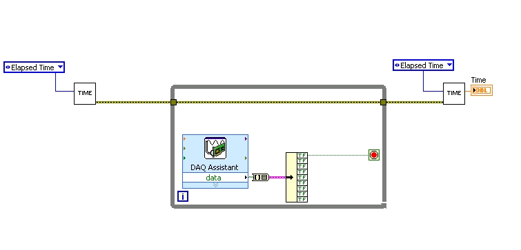
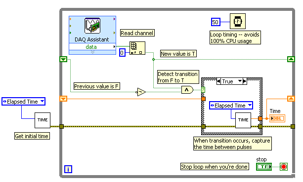
I found a good example of VI on discussion forums that does almost the same thing, only it uses instead of the DAQ Assistant user input. The VI works including the time the program going on in a while loop. I replaced with the DAQ Assistant output (a channel) user input in the hope that it is still work.
When I run the program in "run once" mode, it seems to work perfectly. However, in "continuous run" it measures only a very small interval, probably just the time between two samples. I think it has something to do with the help of a while loop in combination with the DAQ Assistant. Anyone who has any suggestions how to solve this problem?
Thank you!
OK... first of all, you should never use the button "run continuously. I wish that NEITHER would be to eliminate it, but told me that it is sometimes useful for debugging. If you want your program to run over and over again, use a while loop with a stop"" button.
If I'm reading your code correctly, you make your initial moment, and then collect data from data acquisition. When one of the channels is "T", you stop your loop and the end time of capture. (By the way, why you convert your table to a cluster? Why not just index the appropriate channel in the table directly?)
Since you want to capture the time between two consecutive pulses, you need to know when a transition has occurred... i. e when your digital line went from F (no pulse) to T (pulse start). This will give you your forehead. Right now, all you're doing is looking for a value T - so you have no way of knowing if you are looking for to the previous impulse again, or a new impetus. You also burn 100% of your processor with the way you have your programme in place.
You need a small loop delay so that your VI is not 100% of your hogs CPU time. Given that you can live with an accuracy of 50msec, what I suggest that you use.
See attached picture for you give an idea of how to implement. He will probably need some refining operations, but it should point you in the right direction.
I hope this helps.
Maybe you are looking for
-
my nano shuffle will not pass the test of synchronization, but diagnosis detects the ipod
-
Open the cover satellite 5000?
I tried to open my lap top to get out the dvd drive, but I can't get the cover off. for me, it seems that there are still 4 screws left but does not unscrew. I thought u could just remove the dvd drive. If it screws or do I have to pull harder (I don
-
Hello I have problem after restoring my iphone 6 1 or 2 weeks ago, I put my apple with this id * but ID not enable find my iphone, this time, my ios is 8.4. before that I didn't put everything on icloud my iphone apple ID 6. before restoring already
-
Equium A100-027 - bad wireless connection
My Toshiba Equium A100-027 has problems connecting to a wireless network.We have recently received Virgin broadband and it works for everyone! It is only wireless which is faulty, when the cable is connected it works fine.Is it possible to test if it
-
HP Envy 6 1202sa: no audio output device is installed
Hi all! I think I'm having a crisis soon enough. I've updated for Windows 8.1 earlier, but it seems to trow a curve ball at me from time to time. Today is the IE its IDT high definition that audio Codec cannot be installed correctly, the properties d