Detect the Signal DC reduction
I have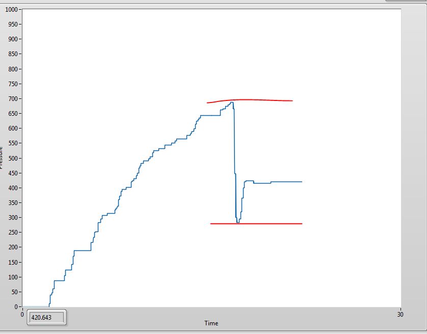
As data are collected you can compare the previous points of new points. You can come up with some kind of diet, maybe a moving average, etc...
You would probably use a loop to store previous values in a shift register, or store a table of five (or any number) values and compare means or from first to last, etc...
It must be a value for the threshold, if the change is <> a threshold and then perform an action. If the comparison is true, you can stop the loop.
Difficult to be accurate without a code of how the measures are actually and stored.
Tags: NI Software
Similar Questions
-
WRT110 Wireless - unable to detect the signal/connection.
Recently lost connectivity to an existing wireless connection I had set up over the past months. The two XP laptop with Dell Wireless WLAN Card and box of Wii is no longer connect or detect the signal. Curiously, WiFi stood momentarily after the reset of power on the router but then disappeared. I connect well with connection wired and mobile detects all my neighbors SSID. All the lights on the router are bed... but no wireless signal. I even joined a wireless USB device to my desktop pc to test. It detected all the SSID of the neighbors but not mine. Even with the laptop.
Troubleshooting steps I did:
-Router-
Power recycled.
Held reset button.
Linksys firmware to 1.0.5 update
Configuration is modified to enable the SSID Broadcast
-Laptop-
Card driver WLAN Dell upgrade vA17 4.170.5 to 4.170.77.18 vA22
People with disabilities Dell Wireless utility and enabled Windows Wireless configuration. Either the Dell or Windows detected my wireless signal wireless utility. Both will detect AND connect to the open connection of the neighbor.
Appreciate any idea or other troubleshooting suggestions.
Readjust the settings of your router wireless...
Open an Internet Explorer browser on your computer (desktop) wired page. In the address bar type - 192.168.1.1 and press ENTER... Let the empty user name & password use admin lowercase...
For wireless settings, follow these steps: -.
Click on the Wireless tab
-Here, select manual configuration... Wireless network mode must be mixed...
-Provide a unique name in the name box of the wireless network (SSID) in order to differentiate your network from your network of neighbors...
-Set the Standard - 20 MHz Radio band and change the Standard channel to 11-2, 462 GHz... Wireless SSID broadcast should be enabled and then click on save settings...
Please take note of the name of the wireless network (SSID) because it's the network identifier...For wireless security: -.
Click the sub-tab under wireless > Wireless Security...
Change the mode of WEP wireless security, encryption must be 64-bit. Let the empty password, do not type in anything... Under type of WEP Key 1 in all 10 numbers please (numbers only and no mailbox for example: your 10-digit phone number) and click on save settings... Please note the 1 WEP key as it comes to the security key for the wireless network...Click the settings advanced wireless
Change the interval of tag to 75 > change the Fragmentation threshold to 2304, change the RTS threshold to 2304 > click 'save settings '...
Now let's see if you can locate your wireless network and try to connect... -
My 'Windows Media Center' does not detect the signal Uverse
After my reading a previous post, I tried manually configuring in antenna / analog and all I get is static. It seems that I am unable to go back and try again.
How you set up Uverse to 720 Lenovo? I ran it through HDMI but want to run via the Media Center.Hello
Thank you for the question to Microsoft Community. I'll give my best to help you.
What is the accurate and complete error message you get?
I suggest you try the following steps:
a. open Windows Media Center.
b. click 'Continue' on the Media Center configuration page, then choose "Custom".
c. Select "System requirements" and Windows Media Center will check your connection network and U-Verse. Click on 'Next' to continue the installation and access to optional "Installation."
d. Select "Set Up My media centers" on the optional configuration screen. Click "next".
e. add multimedia files to Windows Media Center. Select one or all the following folder options: music, photos, videos, recorded TV or movies, and then click "next".
f. Select "Add files to library" and click "next". Choose the folders you want to add to Windows Media Center. Click "Finish" when you are finished adding content. -
Detect the PEAK, mount and average
I use a loop in LabVIEW 8.5 to capture the signals emitted continuously by a card, peak detector.VI is used to detect the signal peaks, then fit.VI nonlinear curve is used to climb the summits, signal now capture, detection of peaks, mount and display pics are all works very well permanently, but there are still some problems annoying me.
1. the received signals is not very stable, so editing results expected on average for 100 times, then how can I averaged the results of fitting on the condition that the capture of signal is not interrupted, this is the time loop does not stop, when the average is made this time, average is reset for the next 100 fitting results can be average again?
2. There is another way, that's 100 results of fitting is automatically saved to excel, then the results is an average manually in excel, then how to store results like this: the first 100 results of connection are stored in an excel file and the next 100 results for other excel connector or they are stored in an excell , but in different columns? Of course the thses are subject to the capture of signal is not interrupted.
3. There is a threshold for the detector.VI peak, but the captured signals entry isn't very stable, so the number of peaks detected is not the same every time, like this time, the number of vertices is 40, next will be 39, this will affect the results of fitting slightly, then how do to detect the same number of vertices every time such as the number is 40 each time?Any advice will be appreciated!
Maybe the pic attached detect.vi 'test' can help you. "medium signal.vi" is a sub VI on average the signal in a way online.
There are three methods using the input signal:
1. no average.
2. average exponential.
3. linear average.
Your problem is when the input signal is damaged by some noise, and you want the input signal before the detection of peaks on average. I use white noise to simulate a noisy environment.
By default, the average mode is 'Linear', and the number of averages is 50. The more averages, the best on the result, but more time to update.
Swith mode between 'Linear' and 'No way' to compare the difference before average and average.
Average exponential is not appropriate in your case.
Let me know if it works for you.
-
Media Center cannot detect the CBS signal
When I connect my antenna directly to the TV, I pick up CBS (channel 19-1) live without any problems, but no matter what I do or I place the antenna, when I connect the antenna to my dvr PC, Windows Media Center does not detect any signal of CBS and the intensity of the signal never changes. All others, the stations/channels are, even those from Akron, who are believed to have weak signals. I tried to add a new channel 19-1 with the frequency provided online, but WMC will not let me create another channel to 19-1, indicating the number of the channel is already in use even when the original channel is deselected. I have a friend in the region, which also runs a PC dvr and he says that he can not get CBS via WMC or another.
Any ideas?
PS. The PC dvr currently has Windows Vista, but I intend to upgrade to Windows 7 in the near future.
Hello
I suggest you post this question in the community of Experts Windows for
Windows Media Center.
http://experts.Windows.com/FRMS/windows_entertainment_and_connected_home/default.aspx -
I want to detect and use the video entering via the HDMI port on the computer. I was told the HDMI port was not set, but I can't seem to find the signal or the video. Any suggestions?
As Tom SC replied, you must contact the company that manufactured your computer. In general, the ports HDMI on most computers is an out-bound port, send video / digital audio output.
You should probably use a video capture card that can capture from HDMI source,
-
Using an 53131A, how do I detect the condition of no input signal?
Hello
I use an Agilent 53131 A frequency counter to measure the frequency of the oscillator. I need to be able to use the frequency counter to read the frequency when the oscillator is oscillating and indicate when the oscillator is bad (no signal present on the 53131A of entry). Does anyone have any suggestions on the type of command I should use?
FETCH?
READ?
MEAS?The problem I have is in the trigger. When the oscillator is bad, the counter hangs up because she continues to wait for a trigger that will never come.
Thanks for any help
In fact you have right to the solution yourself. You need to revise your release scheme or you can use the absence of trigger as your indication.
For example: you know that the measure will have x seconds to complete if the signal is present. If you need to determine whether the measure is right here. Simple if you use GPIB-
(1) set the property of VISA TMO to be as long as you wait for the measure.
(2) enable SRQ on operation completes in the meter. (ATTENTION: make sure that no other instrument allows to block Service Requestby the meter setting as low as possible address)
(3) when you send the boot command, you can query the status of the SRQ with the "wait for SRQ.vi" If no signal is present, then the wait fo SRQ will return with a time-out error.
(4) clear the error since you know what caused it and send a clear command (* CLR) at the counter to return to the idle state.
Alternatively, if the signal is present, the meter will trigger SRQ when the measurement is finished and you can then extract the memory reading.
-
No signal found by HDMI or DVI monitor. Monitor detects the VGA signal very well.
That is the problem. I used to get a signal from the HDMI cable or the cable DVi on my old monitor. Then, the signal was there sometimes, and then it isn't. Now my new monitor does not have an HDMI or DVI signal. He finds the signal to the VGA and that works. Any ideas? Myself and a few others have no idea on how to solve this problem >
Hello, billiardsnut
You use a DVI or HDMI adapter?
Assuming you are using a straight DVI-> DVI or HDMI-> HDMI Cable, try to turn off the computer and turn off the monitor, connect the DV or HDMI, then turn them both.
Some video cards will not dynamically change on its own, following the steps above will generally establish the proper output.
In addition, since you mention on your old monitor that it is intermittent, it might be that the digital (DVI/HDMI) port on your graphics card is a failure.
David
Microsoft Answers Support Engineer
Visit our Microsoft answers feedback Forum and let us know what you think. -
40TL933F - lost the signal while turning on Xbox or ADSl box TV
Hello everyone,
I just bought a 40TL933F yesterday and I watch TV via an antenna: everything is good, but when I turn my xbox or my router, the signal is lost. He then reappears when I turn my xbox.
Does anyone have an idea to explain and fix it?
Thanks for your answers,Socrate25
Would it be possible that your TV will automatically switch to the channel where the Xbox is connected?
I have another TV and something similar happens to me if I turn on my blue ray player.
The TV detects the blueray drive and will automatically switch to the HDMI port where is connected the BD player. -
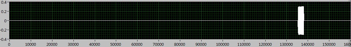
How to extract the signal from the waveform of my power level designated?
Hi all
How can I extract the signal of the waveform accroding to the power level? I read the Trigger & Gate .vi, but this vi retrieves the signal duration. I want to extract the signal depending on the power level.
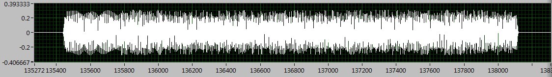
As shown in the following figures, the signal I want to deal with is between 130000 to 140000, if I Zoom, I can see the useful signal is between 135400 to 138200. The question is how to extract the signal in the area?
I tried the sub_NoiseEst_And_Chop_Shell.vi in the example of Packet_based_link also, but this Subvi seems to be a bit slow. Can someone give me the best advice? Thanks in advance!
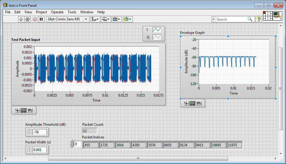
I'm working on something similar, but have not had time to fully develop.
My idea was to use an envelope detector (low pass filter) and then use a detection of energy VI on the envelope.
Here is where I left
-
Hello world!
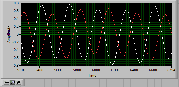
First of all, I use a USRP as a transmitter to emit a sine wave (the signal is exp(j2*pi*f*t)), and then I use the external clock to synchronize the two USRPs (Ref as PPS in are connected to the clock) as receivers. Receivers are in sync, and they are at the same distance from the transmitter, I thought that the signal they receive should have a nearly the same phase. However, in practice, the phase shift is big enough, and this problem really confuses me.
It's the received signals of 2 receivers.
Yes. What you observe is expected.
Near the bottof of this document read the area 'alignment Phase vs Phase coherence '.
http://www.NI.com/white-paper/14311/en/
And also, for the alignment phase, see the following 'Angle of arrival detection with NI USRP '.
https://decibel.NI.com/content/docs/doc-25716
Erik
-
filter the peaks on the signal from ECG pulse!, help!
Hello
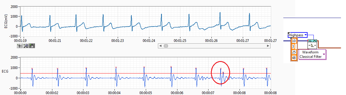
I have RCV of the ECG signal. I filtered the ECG signal and get the resource (interval between each pulse of ECG) records.
The source of the signal have noise I use a threshold but sometimes spikes of failure. Like the previous capture. Normally, if you get a pic of fault detected, I'll try to find this index to add to the left or right of the peak, normally I add to the lower value. This works if it has only a bad impulse between 2 good.
The problem come when I have more than a ridge between the two coupons.
Also, when the impulse of R a loss threshold I have trying to find the index and get 2 new reading making division 2 peak value.
I have attached the method I've used to adapt it. I only works if I have 1 Ridge added on real measures of R or pulse 1 loss R, when I have several pics no work.
I would like to hear an idea to make it work better. I don't like the idea of removing the value interval, I have 2 hours of reading and if I remove the values I have lower data outoput is why I tried to summarize or division of values to get the correct reading without losing any data.
Perhaps, there is any better filter for ECG of entry, so I have a R-own pulse and less noise between ECG pulses.
Any advice is welcome.
Best regards, Fred.
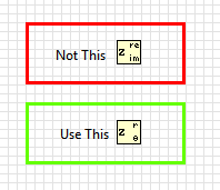
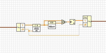
Almost. in the last step, you have extracted the real part of the complex waveform. Instead, you must retrieve the extent.
BTW, this idea isn't mine. I got from this article
http://www.ScienceDirect.com/science/article/PII/S0010482501000099
-
ProBook 4720 s does not detect the SD card inserted
I get no response when a SD card snaps, but 8 GB Transcend card is recognized very well of my little netbook from Toshiba.
This is the first time I tried a card in this HP, although I got it a few months. Running Win 7 Pro 32-bit. BIOS HP 68AZZ worm F.0F 18/02/2011.
Well, I contacted HP support and got a helpful response within a day. Siva gave me urls for two drivers that I apparently needed (not very new drivers and I don't know why they were not there in this new machine, but any way..) and they installed, unlike the one I found just for me and giving a message "forbidden". However, once installed, both raised the box "this program cannot be installed correctly" (that I've seen before and never known what to do about it except devoted to work and hope for the best).
With the drivers installed, the system * fact * detect the SD card so that it has shown in Device Manager and gave sound signals when it has been installed and removed. But he does not have assigned a drive letter and did not show in Windows Explorer, while it was still incommunicado or to serve as a ReadyBoost file storage.
Thinking that it seemed that HP problems were over and it is now a Windows problem, I spent a few hours to make the seemingly useless things in Windows, all having to do with recovery of AutoRun, which is not.
Now the SHIFT key while inserting the SD card could start AutoRun. Also, I gave the command 'net start shellhwdetection' and told me that the service was already running. And AutoFix.exe from Microsoft verified that the shell hardware detection service was on and the autostart value. But to step next, as the wizard repair didn't see that other readers, not the SD card, so I couldn't specify only * that * drive AutoPlay wasn't working on, and which ends the program.
Support software MS said that if ReadyBoost enabled and there (and it was) and still does not work there because some services he needed had been extinguished. So I Dove to the various lists and tried to turn on anything that seemed relevant and which has not already lit. Nothing seemed to still accept my changes. Very frustrating. But then I went back to where I had left access control panel in Explorer, and I saw that the SD card has sometime been recognized and awarded drive E. Shazam!
Therefore, all followed the script and I could bring up the window of the tab (in the properties of the drive E) option for ReadyBoost and say, go ahead. He did, and it seems to work very well. It closes fast when I close the lid, with several major programs running, as well as 4 windows in FF with about 12-24 tablets of each, and it took only 60 seconds to wake up this morning.
So the problem is solved with something good help at HP, but not gracefully or usefully for others, I'm afraid, because I can't say yet exactly what I did.
-
to detect the meter output via the parallel port
I need to detect the meter count trigger, to perform an operation every time. I think passing the input signal pins (pins of status or control). The meter uses is omron H7EC.
I lowered the voltage of 24 V to 5 v with resistors.
But I can't get the entry via the parallel port.
All the stems of my status are still high.
What should I do, please help.
In the parallel reading write loop.VI, the splash screen is attached.
I suspect the entries on the parallel port pins have a resistance low pullup to 5V, so they tend to float high (logic 1).
Try to add a 4 700 Ohm resistor between pins of entry and mass of the parallel port, see if it then reads down pulldown (logic 0). If so, then keep the resistance in place and connect the signal of 5V that you want to monitor at the entrance.
-AK2DM
-
Determine the position of a part of the signal on a graph
Hi all
I have a problem. I determine the position of a part of the signal on a chart. So, I have to determine the maximum value of the part (this is not a problem).
Signal a lot of noise. I did some filtration but still signal have noise. Concerning this, filter change signal, two later when I take one measure, there is a possibility that this is not true.
Anyone has idea how to determine the position of a part of a signal automatically, for the various signals (similar).
There are photos attached where is what belongs to an interest in a signal. There is a VI where is an a test signal.
Thank you
Hello
From the screenshot, I understand that you only interested in the local maximum of the signal.
There is a VI that detects peaks when you specify a certaing point and this point maximum width.
Later, it's just a matter of setting the value of local maximum of you. Basically, you'll have to point once again got 1 d table than VI.
I enclose a VI that can be a good starting point for your application.
Best regards
Ion R.
Maybe you are looking for
-
I tried to restart Firefox, nothing helps. Then I tried to restart my desktop computer Dim screen with taskbar with icons, hourglass cursor that does nothing on tasckbar only. I tried to close everything down and restart - without success. I write fr
-
How to recharge the remote control for Apple TV 4
How to recharge the remote control for Apple TV 4
-
Satellite Pro M - register pop up on startup
Whenever I boot, I get the pop up on the desktop telling me there is something in my registry files, it cannot open, the only way I can describe it is looks like a word of Chinese, followed by a circle. Allan
-
HTC WILDFIRE S no video calling
Hi, I'm using HTC's wildfire. I have no option to enable video calls. Help, please. Even his does not work for video of my partner. Please tell me how I can activate the video on my mobile.
-
Hello I would like to choose a KING in an image and then use it to read the number on the LCD. I have attached below the VI and an example of the image I want to use, could someone clarify why the VI does not work properly. Thank you Zied