Detection of edge in the binary image
Hello
I have an image that I play with Vision Assistant. I used the threshold function for binarise, and I have now two blobs straightish separate in the right corner below. I want to be able to detect the outer edges of this pair of bloba, but can't seem to do it using the edge detector or Straight Edge tools.

Can you help me please?
Thank you!
Dave
Most of the failure of a difference of 20 or more edge edge detection routines. Since it is a binary image, the difference to the edge is 1. You can set the contrast of the min on 1 edge detection routines, or multiply your binary image of 255 to get the high contrast edges. I like the multiplication because it is quick and easy.
Bruce
Tags: NI Hardware
Similar Questions
-
edge of the visible images through the mask
I do a screen split using position, a solid black layer effect and masks and for some reason that the edges of one of the clips and the black solid layer are appearing through the mask like what seems to be 1 width in pixels. It appears in the record. You can see that the two lines just to the left of his head. What I am doing wrong?

So it turns out that this is a bug and is also a novelty, I arrived just to never try until the day where it became available, no wonder no one could help me with it, it has never existed before! Now in the cropping effect, there are a few form buttons that will make masks. However if move you the position of the image, it only covers the last width in pixels of the image. BUT! If you make a 2nd mask then lay on this line annoying that it will remove. I guess they'll fix that in a patch later.
-
Saving binary Image with overlay?
Hello
I'm having some trouble in saving an image with overlay information. I use IMAQ find circles to measure the rays of the holes in a binary image. Hole data is then used with oval Overlay IMAQ, draw on ovals to highlight detected circles. Works very well and the image is displayed as expected in the output of the image on the screen, the palette has the binary value. (See the second image of 3, below)
When I try and save the image in PNG I just get a blank image (black). If I use the overlay IMAQ merge tool, I just get the green circles on the black (see the last picture of 3 below). Is there something I'm missing with pallets/fusion? Any help much appreciated. Snapshot of the (messy) code attached.
The problem is that the binary image is all zeros and ones. A normal image goes up to 255, so the value 1 appears black.
One solution is to multiply the binary image of 255, which makes the image black and white.
Bruce
-
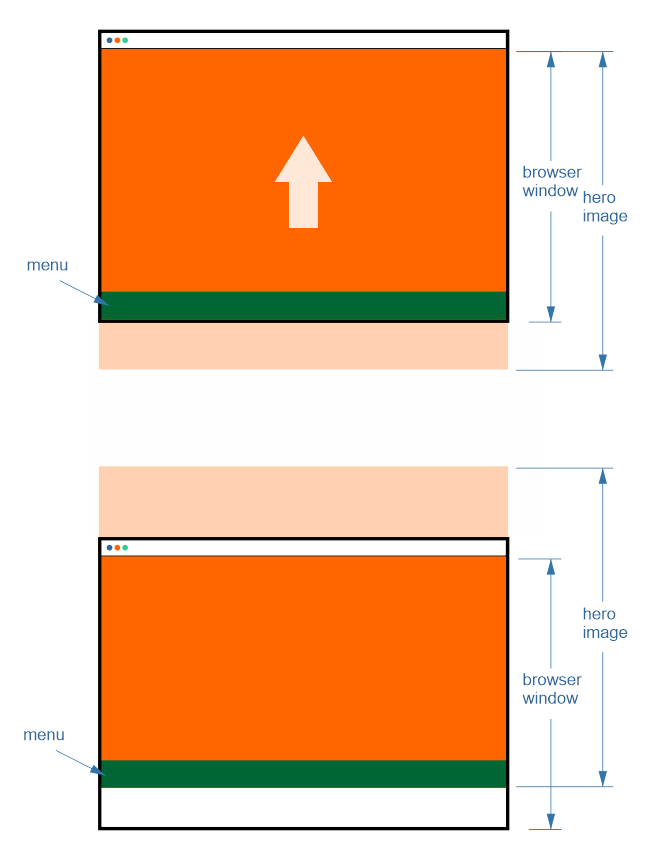
How to attach the menu strip to bottom edge of the image of hero?
Hello
I have hero image in the header of the page which is a height equal to or greater than height of the browser window. I also have the menu which is aligned with the lower edge of the image of hero. Now I need the menu would be glued to the lower edge of the window of the browser until the time where (the vertical scrolling) lower edge of the image of hero is visible. Like this http://c2n.me/3ucUh4i.png
Is it possible to achieve in Muse?
Thank you
Alex.
Because you can't make A Menu disappear with a fluid layout.
-
When I use my clipping on an image mask, fills the form I use the whole layer instead of just being a small shape Panel and then I put my picture on the shape layer, a clipping mask, but the form becomes clear with just a slight edge. The photo behind it does not move. I did this project of class before and it worked fine so I'm not sure if I have something started or... Any thoughts?
I thought about it. That's all just stupid on my part and a bit of frustration because photoshop is my sworn enemy of then adobe added in. Thanks tho!
-
Lock the images to the edge of the browser? Is this possible with the Muse
Can someone tell me how to lock and image to the edge right and left of the browser window? I have pictures that I want to appear as if they come out on the side of the browser on both sides.
In Muse I placed these images at the edge of the browser window and the 'line' goes red, I thought meant lock to the size of the browser. However, this is not what is happening. It seems in Muse, but when I download on my server the images float in the middle of the screen.
Is there a solution to make it work?
Thank you.
Fixed!
Im not a web guru, but I figuered how to solve this isue on cc updated muse 2015
Go to the properties of the page
Uncheck the Center horizontally
and the padding value 100 left
I did and once I started to draw inside the box everything has started to align with the left right etc..
hope this helped...
-
Cropping tool magnetic snaps at the edge of the image
The truncation tool magnetically clings to the edge of the image. Quite often, I need to remove a few lines of pixels from the edge of the image. Because of this feature to hang, this task can be frustrating: we can't GET the tool you want, he will jump on the edge.
This function has bugged me since I use photoshop. Is it possible to turn this off, or work around this problem?
Disable snap. View > snap. You can also disable individual items to slam in view > snap to > guides / layers / limits of document / etc.
-
Moto G3 - lack of concentration on the edge of the image
Hi all
I recently bought Moto G3 after owning Moto E2. I decided to do it because of better camera and a flash.
Unfortunately, I discovered that the photos on my G3 suffer the lack of development on the right edge of the photo (or left, or low or high, depending on how I am now). I have to say my best update automatic E2 manipulated. I would like to know if it of just my phone or is - this common among all the G3s. I have attached the photos for comparison.
Here is a link for more pictures:
https://drive.Google.com/folderview?ID=0B9ufszI2lUPgZEoxNnF0M01YZFE&USP=sharing
I see that the photos are normal.
-
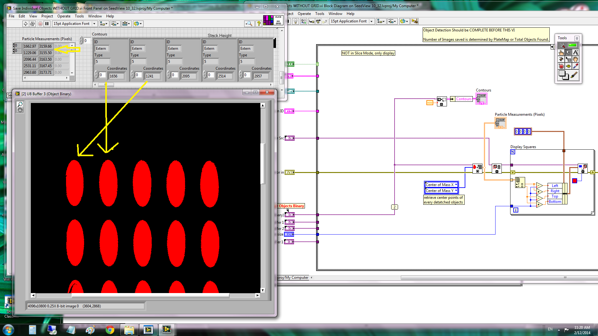
How the binary objects are sorted
Live treatment image "IMAQ particle analysis" and "IMAQ MaskToROI.vi" returns the characteristics of binary objects detected in a specific order. My question is how objects are sorted before results are returned.
Look at the following example. I'm totally confused why two screws returned the second object in the first row first?
I was trying to get the centers of each object (and their contours) and assuming that they were sorted by their positions on the y-axis first and then positions itself on X. It is most of the time, until you see here on the first line. What happened here? Why the second object is sorted as the first object? HOW the binary objects are sorted anyway?
I got it. It has to be sorted by the corner up and left of the rectangle of the object.
-
Adds data to the binary file as concatenated array
Hello
I have a problem that can has been discussed several times, but I don't have a clear answer.
Normally I have devices that produce 2D image tables. I have send them to collection of loop with a queue and then index in the form of a 3D Board and in the end save the binary file.
It works very well. But I'm starting to struggle with problems of memory, when the number of these images exceeds more than that. 2000.
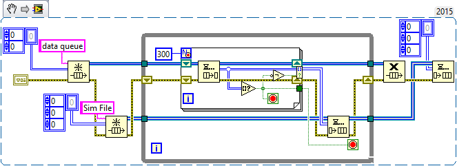
So I try to enjoy the fast SSD drive and record images in bulk (eg. 300) in binary file.
In the diagram attached, where I am simulating the camera with some files before reading. The program works well, but when I try to open the new file in the secondary schema, I see only the first 300 images (in this case).
I read on the forum, I have to adjust the number of like -1 in reading binary file and then I can read data from the cluster of tables. It is not very good for me, because I need to work with the data with Matlab and I would like to have the same format as before (for example table 3D - 320 x 240 x 4000). Is it possible to add 3D table to the existing as concatenated file?
I hope it makes sense :-)
Thank you
Honza
- Good to simulate the creation of the Image using a table of random numbers 2D! Always good to model the real problem (e/s files) without "complicating details" (manipulation of the camera).
- Good use of the producer/consumer in LT_Save. Do you know the sentinels? You only need a single queue, the queue of data, sending to a table of data for the consumer. When the producer quits (because the stop button is pushed), it places an empty array (you can just right click on the entry for the item and choose "Create Constant"). In the consumer, when you dequeue, test to see if you have an empty array. If you do, stop the loop of consumption and the output queue (since you know that the producer has already stopped and you have stopped, too).
- I'm not sure what you're trying to do in the File_Read_3D routine, but I'll tell you 'it's fake So, let's analyze the situation. Somehow, your two routines form a producer/consumer 'pair' - LT_Save 'product' a file of tables 3D (for most of 300 pages, unless it's the grand finale of data) and file_read_3D "consume" them and "do something", still somewhat ill-defined. Yes you pourrait (and perhaps should) merge these two routines in a unique "Simulator". Here's what I mean:
This is taken directly from your code. I replaced the button 'stop' queue with code of Sentinel (which I won't), and added a ' tail ', Sim file, to simulate writing these data in a file (it also use a sentinel).
Your existing code of producer puts unique 2D arrays in the queue of data. This routine their fate and "builds" up to 300 of them at a time before 'doing something with them', in your code, writing to a file, here, this simulation by writing to a queue of 3D Sim file. Let's look at the first 'easy' case, where we get all of the 300 items. The loop For ends, turning a 3D Board composed of 300 paintings 2D, we simply enqueue in our Sim file, our simulated. You may notice that there is an empty array? function (which, in this case, is never true, always False) whose value is reversed (to be always true) and connected to a conditional indexation Tunnel Terminal. The reason for this strange logic will become clear in the next paragraph.
Now consider what happens when you press the button stop then your left (not shown) producer. As we use sentries, he places an empty 2D array. Well, we dequeue it and detect it with the 'Empty table?' feature, which allows us to do three things: stop at the beginning of the loop, stop adding the empty table at the exit Tunnel of indexing using the conditional Terminal (empty array = True, Negate changes to False, then the empty table is not added to the range) , and it also cause all loop to exit. What happens when get out us the whole loop? Well, we're done with the queue of data, to set free us. We know also that we queued last 'good' data in the queue of the Sim queue, so create us a Sentinel (empty 3D table) and queue for the file to-be-developed Sim consumer loop.
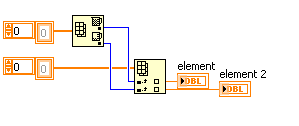
Now, here is where you come from it. Write this final consumer loop. Should be pretty simple - you Dequeue, and if you don't have a table empty 3D, you do the following:
- Your table consists of Images 2D N (up to 300). In a single loop, extract you each image and do what you want to do with it (view, save to file, etc.). Note that if you write a sub - VI, called "process an Image" which takes a 2D array and done something with it, you will be "declutter" your code by "in order to hide the details.
- If you don't have you had an empty array, you simply exit the while loop and release the queue of the Sim file.
OK, now translate this file. You're offshore for a good start by writing your file with the size of the table headers, which means that if you read a file into a 3D chart, you will have a 3D Board (as you did in the consumer of the Sim file) and can perform the same treatment as above. All you have to worry is the Sentinel - how do you know when you have reached the end of the file? I'm sure you can understand this, if you do not already know...
Bob Schor
PS - you should know that the code snippet I posted is not 'properly' born both everything. I pasted in fact about 6 versions here, as I continued to find errors that I wrote the description of yourself (like forgetting the function 'No' in the conditional terminal). This illustrates the virtue of written Documentation-"slow you down", did you examine your code, and say you "Oops, I forgot to...» »
-
iPhone 7 screen purge / uneven edge of the screen
I noticed on a background of intermediate color as the backlight on my 32 GB iPhone Black 7 is uneven on the right side of the screen and I see dark spots 7 or 8, almost like a series of rectangles will light dark light dark. You don't see them on a white background or against black, but only against colors flat (a gray screen at 50% for example).
ITI is particularly notable, if I pull the low notification Center or go to multitasking where the wallpaper becomes a pale blur.
I tried to capture on camera as best as I can as shown on the attached photo (ignore the white line of thinking above).

I don't know what is my best option, because stocks appear to be low, so I can't even order a new and send that back as the day 14 return policy runs out next Friday and another would not happen for 2-3 weeks. I can't imagine having enough stock to swap Apple stores either.
I was wondering what think and what would be the best course of action.
Given that I can't edit my original post, I would also like to add:
These are dark spots certainly that the screen is uniformly bright above and below the area as apposed to bright spots that you wait with purge of 'normal' screen).
Scroll the app facebook for example, you notice that it is when an image that goes to the edge of the screen and you saw a difference subtle when the image scrolls clear/dark areas.
-
Hello everyone.
How to save a binary image in a computer? If I right click on the image, then choose "Save Image... ', the saved image will appear empty. I understand that the image is in 0 and 1 but I do not know how to implement the code.
Thank you.
Use IMAQ multiply to multiply the image 255 times.
Bruce
-
Detection of peak at the same time
Hello
I have two waves A and B with 10000 sampling point.
Now, I want to find Max and Min waveform peak value has and correspond to what I want to know the respective value of the B wave.
So end of thw Finally I have the Max value of A and this is the respective value of B.
For this so I want to know the basic idea.
Thank you
After samples were taken by the waves. Use "Table Max and Min" on a range, or edge detection
Then connect the clues of the max and min for "Index Array" of table B.
-
Photosmart 7515 adds lines from bottom of the scanned image
My photosmart 7515 started just add a line double about 2 inches from the left edge of all of the scanned images. NO modification of the system that I am aware. Prins computer or internet as usual. Any ideas?
Hi Bobvan1,
Welcome to the Forums of HP Support!
 I see when you scan with your HP Photosmart 7515 he started to add a double line about 2 inches from the left edge.
I would like that you start here: vertical, lines or streaks in the Copies or Scans, please fill ALL troubleshooting steps, focusing on cleaning.
Let me know the results, I'll watch for your reply.
Thank you
-
Single channel match trigger speed model vs onset of edge on the PXI-6562
I think that my question boils down to this: what function does the edge of trigger plan that is not provided by the model match trigger?
As far as I know, the only differnece on the PXI-6562 is the edge trigger has its own pins dedicated (PFI pins and pins RSTI) to detect a trigger, while the model match trigger detects a rising edge or falling on a regular input pin.
Is there a difference in performance (for example, the time to rearm)?
Are both triggers synchronous types with the sample for dynamic acquisition clock?
On my application:
I acquire a signal off a SPI bus, triggering the CS line. I start to acquire data when the CS line going down and stops when the CS line is high. As I acquire data CS on a regular supply, it seems logical trigger on a pattern for this channel only match. I'm curious to know if there is any advantage to connect a PFI PIN to my CS of entry so that I can start using digital edge type.
Thanks in advance,
Arthur
Arthur,
There is no difference with regard to performance using a digital camera compared to a type of pattern match trigger. Specifications for rearm time reference to the trigger type (Start, reference, etc.) in the samples to rearm, and there is no difference with the performance when you use a digital advantage over a line/PFI line Trigger and a correspondence to the model used on the input signal. Change the source of the trigger itself will not change the performance of the material that occurs after the trigger is received. This behavior to sync with the clocks of acquisition regardless of the input source. We're just looking at different sources for the jury to look for a given trigger.


Maybe you are looking for
-
announcement on installs without permission
There is this addon that installs without permission. 'S called it funklyrics 1.122 it seems to be able to turn on even after being disabled. It seems the ride through an update. The program itself seems to be harmless but implements small adds tryin
-
Re: Satellite L550-129 does not support the Toshiba external HARD disk
Toshiba Satellite L550-129 does not support disk Toshiba store.e canvio external hard. Al other portable thosiba in the family meets the canvio store.e and many former protable?
-
HP Officejet 8610: what impression
Under windows 7 and HP 8600 (I think) I could see what was printing and what was waiting to print. Under windows 10 and HP 8610 I can't find the option to do this. Thanks.
-
remove the wireless network problem
-
Visual Studio 2010 Tools for the Installation of Office Runtime failure
Hello the installation fails with the error code 1601. I studied this code but received no responses that could solve my problem. complete logs are pasted below. any help it will be appreciated. The following properties have been defined:Property: [A