digital meter
Hello, I am working on a counter, but I need help to do the following:
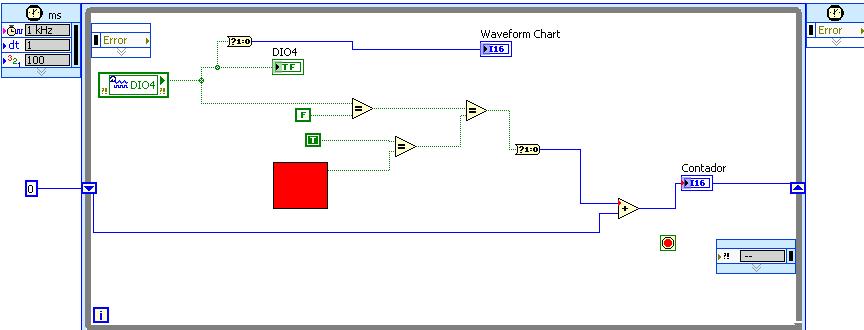
Instead of the red square in the image, I would like to have the last was received by my digital input of entrance and compare it with the following entry.
I want to do it because when my speedometer working I Don t want to increase more 1 time during playback of a false entry. I just that it increases its value when it reads a new set to false.
for example:
entry = F and F was the last measure, I Don t want it increases its value
entry = F and the last measurement was T, I want that it increases its value
entry = T I Don t want it increases its value
How could I do? with a shift register I can do, but I want to reduce my code in labview, thank you
Tags: NI Software
Similar Questions
-
color of the digital meter ramp or slide is missing the performance
Hello
I, m using CVI 2010 (10.0.1. (419) on windows 7-64 bit.
In a simple program, I use a digital meter. I also use the color of the digital counter and on the IUR ramp, I see the ramp as expected with the defined colors. But when I run the Panel (in the debugging or mode of publication), the instrument (meter) shows but without the color ramp. If I save the uir file, close it, then reopen it, the ramp of color in the file of the IUR is also missing, so I have to configure it again. It's the same with a digital slide.
I think it's a bug? Someone at - it the same problem?
Greetings from bremerhaven
Norbert
My guess is that you have inadvertently saved the. IUR in an old format (8.1 or older). In the user interface editor, check the bottom right of the window to see what the current format of the. IUR is.
If this happens, you will have to change via file > save as.
Luis
-
Digital meter as ammeter connection
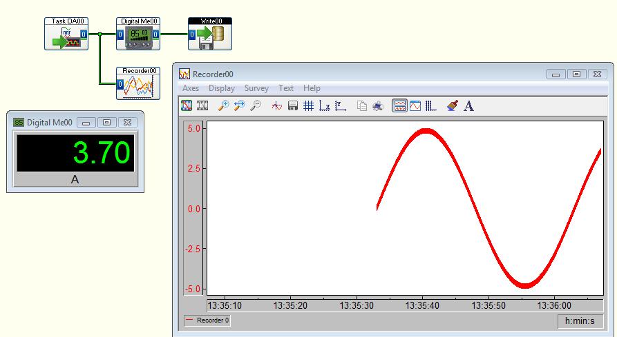
I'm new to DASYLab and I'm trying to connect a digital meter module to display current measured by a NI 9227 current DAQ. I copy the entries on the exits of the meter and then treat the meter as being in the current path? In addition, connect the current DAQ in the path that I expect that it is electrically with a release?
Don't know exactly what you're asking.
Here's what I'd do from step 0:
Step 0: create a task NEITHER-DAQmx in MAX (Measurement & Automation). Configure it to CONTINUOUS sampling and the value of the samples read to be about 1/10th of the sampling frequency. For example, it the sampling frequency is 25K (Hz), and then configure the samples to read 2500.
Save and run the task to test. Stop the task. Close the MAX.
Step 1: DASYLab open and create the analog inputs of NOR-DAQmx. Configure the following task that you created.
Step 2: Create a digital meter module. Connect the output of the analog input to the input of the meter.
That's all.
If you add more logic, you can configure the DMM to 'copy the entries' and connect your logic to the digital counter, or you can PLUG the wire between the analog input and counter to connect to other modules.
Logically, it is the same thing. The output of the meter is simpy the same data that are placed in the entrance of the meter. He is not treated or changed somehow by the meter.
I've set up as a simulated device, and it's what might look like a spreadsheet.
-
each display elements of files excel on digital meter
Hello
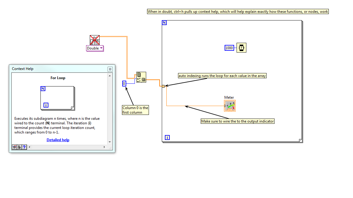
IM new to labview and I need my digital display (meter or gauge) to accept entries of an Excel of column 1 and 10000 lines.
Each item in the excel file IE each line should be displayed to the counter one after another with a second time.
Is this possible to do?
Thank you
Vijay
Hey there
I noticed that you said that you are new to labview. Here is an example of your code that should work, as well as a few links that will help you get started. The subject more variety that labview compared to other languages is the concept of data flow, which works very differently from traditional programming, while I linked an article on the screenshot below. I've also linked an article about automatic indexing, as for strongly your project at hand.
Another tip is to "highlight the execution." The button of the bulb on the block diagram toolbar will slow down and view the program, so you can see how the program works when idling.
Hope that helps!
-
How can I change the data format of the digital display of the digital meter?
I created a screen that uses digital counters to display data. Each meter has its visible digital display so that the user can see the level accurately. I have changed the format of the data from the meter to 2 digits of precision and want to display to have the same format, but there seems to be no way to do it. The digital display is locked to 6 significant figures, which will be confusing for my users. I know that this was possible in previous versions of LabVIEW, but was somehow lost to 8.6.1 and 2009.
I am aware that I could do some "work-arounds" with channels or replacing the digital screens with digital indicators, but it is not acceptable. How can I change the properties of digital signage?
Hi AEI_JR,
on the Properties dialog box, when you set the display format of the counter, you will find a switch to choose between 'Digital' (the default) and "digital display"...
-
HI, I connect acquisition of data USB 6229 quadrature encoder, I connect CH A PFI 0/P1.0 or PIN 73 and PFI 0/p1.1 or PIN 74 and I'm setting them up as a counter or a desk reading in. The USB6229 of data acquisition is not read these signals as a counter. How I would read the counts of a quadrature encoder, using materials DAQ 6229.
Regads;
JH
The fact that it is the reading of thousands and millions usually means that there is noise on the signal that is picked up as the account when it really shouldn't be. To correct this, you must activate digital filtering:
See the example:
Use the digital meter Debounce filter
and page 7-32 to 7-33 of the M series user manual for details of what a digital filter is and the different settings available for the 6229.
Activation of the filter will get rid of the very high frequency on the digital line noise and must get rid of the extremely high values and instead to give a good account of 256 / rev.
-
Hi all
I just noticed this, but the precision (number of decimal digits) must be the same on a meter and its digital display? It does not make sense to me. If the meter not a - 10, 0, 10, why should we be forced to display as - 10,000, 0.000, 10,000 if we want 3-digit digital display below?
In other words, I want another precision on the meter itself and its digital display.
Am I missing something?
I strongly support your opinion! Until now I used to replace the digital meter a meter with an independent digital indicator exactly to reach another level of accuracy between them, but this can be problematic, because you can't forget one of the indicators was updated with strange effects obvious.
Please repost this in the exchange of ideas and I'm going to Bravo this idea immediately!

-
I'm going to build a system to display the hydraulic pressure to tip during an impact event. I use a pressure sensor high frequency Omega DFX101 - 5K, an Omega VAC - PS1 power supply, OM-USB-1608 acquisition, Windows XP, DasyLab Lite, SuperLogics forn small PC, HDMI display. The advanced event lasts about 3 ms and I want to hold and display of pressure Ridge on a digital meter as large as possible on the monitor. I also need to compile the file and run it on a client computer running the Runtime. Not much, right?
With DASYLab Lite you do not have the module of statistical values, but you should have a way to block / Peak Hold module. Configure for Cumulative Maximum. Display in the digital meter set to display the Maximum. You can make as big as your monitor digital meter display.
With DASYLab Basic or Full, you have more options.
With DASYLab Lite, you have the Options-> key Actions that allows you to define an essential feature which can reset the average block module when you click the key combination.
You cannot compile DASYLab in an executable file. The license of DASYLab Runtime executes existing spreadsheets (files *.DSB). You must ensure that the DAQ configuration is the same. With a single device, which should be easy.
-
Hello
I'm trying to read a wattmeter with RS485 Modbus RTU output information I use the analog Modbus Module and I did the test of communication for her and the test is good, but after that I can read the information on the digital meter Module or to the recorder. I tried wiring directly after the analog Modbus of entry. Could you help I can make this claim. Thank you
I'm not sure I understand the question.
DASYLab V11 SP2 delivered a completely revised MODBUS module - which DASYLab version do you use?
Can you tell us what the device is, what kind of data and how the bytes are stored (Motorola vs Intel format).
-
Hi all
I have a digital meter that displays numbers (data) going up and then down and then back up and so on. I would like to find a way to trigger a Boolean value to tell the truth, whenever data is beginning to increase, but I can't understand the logic to do so. Any suggestion would be great.
Node of feedback to follow the previous value, then a larger to make the comparison.
-
Is there a way to find the total number of steps failed during a given run. I see that the State step information are available but it is for the various steps. http://zone.NI.com/reference/en-XX/help/370052H-01/tsapiref/reftopics/stepproperties/
I'm looking to somehow keep track of the number of comparison fails step (step test numerical limit, several numerical limit or string test step test step) for a given execution. Should also follow the steps has no no if they are in the subsequence.
Thank you.
Good afternoon
Add the 'SequenceFilePostStepFailure' callback to your sequence. Follow in the callback for the 'type' of tests that failed with a statement on the type of test box and a digital meter. Increments the counter whenever a specific step fails. You could make a fileglobal and have it print the report. With a little more work, you could push the value to display in your operator interface, if you wish.
Thank you
PH
-
How to set the input frequency output rate linearizer function
I have an input range of 0 to 2000 Hz with a digital meter. I need to convert the signal in gallons per minute (GPM) using a non-linear process with 10 points on the scale. Here are the 10 points of the scale.
In display
0 =.64 Hz DSP0 INP = 0.001 gal/MIN
INP 1 =.83 Hz DSP1 = 0.002 gal/MIN
INP 2 = 0.03 Hz DSP2 = 0.007 gpm
INP 3 = 0.83 Hz DSP3 = 0.025 gpm
INP 4 = 0.12 Hz DSP4 = 0.038 gpm
INP 5 = 01.16 Hz DSP5 = 0,126 gpm
INP 6 = 07.77 Hz DSP6 = 0,380 gpm
INP 7 = Hz DSP7 = 0.503 02.43 gpm
INP 8 = 016.33 Hz DSP8 = 0.637 gpm
INP 9 = 695,22 Hz DSP9 = 1.056 gpm
I need Labview to provide a linear display throughout each segment (i.e. between the sequential characteristic points) so that any entry in the system in Hz translates into a rate of GPM. Any ideas?
Thank you
Toddzilla
This VI works perfectly now. I had to increase the samples per second at 80 k so he could flatten. The function ' scaling and mapping ' is the key to this.
Be sure to enter at least 20 frequency of entry on the front block until you try to run it, increase intake of up to 1700 freq for GPM indicator work...
Thank you all for taking the time to help me.
Kind regards
Toddzilla
-
How can I get the digital power meter?
How can I get the digital power meter?
I use a method similar to the example below to measure the market factor using the inputs of a multifunction data acquisition meter. If the duty cycle is 0% or 100% for a given period, DAQ reading times out and returns an error. In this case, I would get the digital state of the counter of entry so I can put as cycle to 0% or 100%. I want to do it without knowing the digital port and line the entrance of counter... for example I would like to continue referencing DAQ/ctrX since I already have this information.
The application uses an M series: PXI-6229 DAQ and LabVIEW 2011 to make a system customized for VeriStand.
https://decibel.NI.com/content/docs/doc-12396
For the moment I wired the block diagram to add a case structure to check the meter ID and string constants to set the identifier of digital input, as they share the physical connection. As much as I can say that makes the specific code for the PXI-6229 (or any DAQ with only two counters that share connections with p2.1 and p) 1.4
I have attached the VI sub.
When the device is used with a different data acquisition, I can add the connection and/or separate control. Looks like at least one will be necessary given that the meter can only detect the edges... I think it was the piece of information I needed.
Thanks for your help!
-
Hello!
My problem appeared when I tried to update my traditional NOR-DAQ legacy code to DAQmx.
I use 2 meter (meter 5 and 7 meter) on PCI-6602, to generate trains of pulses, as well as the lines of e/s digital port 0 (the form lines from 0 to 7). What I do in my request, it's that I'm starting to generate the pulse train on the output of 2 meters and after that I play with the State of digital lines.
Traditional, it was no problem to use the meters and digital lines at the same time, everything went perfectly, but in DAQmx, is not possible.
What's happening: I start generating train of pulses on the output of counters, no errors, but when I try to change the State of a line of digital port the generation of the pulse train is stopped. What happens when I start the task associated with the digital way.
My question is: is it possible to create a channel on digital lines without changing the channels created for meters?
Another thing that I managed to do with the panels 'Measurement and Automation Explorer' and Test for PCI-6602, is basically the same thing, I generate trains of pulses on the output of the 7 meter and try to start a job on the digital line, but I get an error:
"Error-200022 occurred in test Panel.
Possible reasons:
Measurements: Resource requested by this task has already been reserved by another task.
Device: Dev4
"Terminal: PFI8.On the contrary if I use the counter 0 or a counter 1 to generate trains of pulses I encounter the same problem.
What resources are used by 2 to 7 of the PCI-6602 card counters and the counters to 0 and 1 do not use?
Thanks in advance for any answer!
Ciprian
After doing some real tests on this device, I found that it is a normal behavior for the jury of 6602. This is because when you start a task digital all 32 lines are configured for digital i/o, so it replaces your meter operation. The article below the link explains a little more on this subject. You must start the digital task before the task of counter to use the features of both in your program.
2 meter and above will not work correctly when you perform digital i/o on NI 6601 or 6602
http://digital.NI.com/public.nsf/allkb/43F71527765EEC3886256E93006CD00C?OpenDocument
-
Route of the exits of the same meter, digital output
Hello
I'm not sure it's possible, but I will deliver the outputs of 2 meters (PCI-6602) on the same line of digital output.
My 2 meters each generate a pulse train defined by frequency, cycle of dut and delay. I want to combine 2 pulse trains in a pulse train resulting. How would it possible if I can't deliver the outputs of the counters on the same digital line? What I have to abandon this idea and set the desired binary pulse train and release several times what a digital line?
Thank you very much in advance for all your comments here.
Cheers, Shaun.
Hi Shaun,
I do not recommend you to connect directly 2 outputs.
Why not use a door or 2 entries? Connect the outputs of the meter to the doorways.
If the impulses are well timed and synchronized (they do not appear at the same time)
the output of the gate or will be a combination (in short, actually) of these pulse trains.
Hope this helps,
Maybe you are looking for
-
Can't export videos 4 k on YouTube
After editing a clip from movie k 4 in iMovie on iPhone 6s, I am unable to export it to YouTube in 4 k. The drop down menu includes up to '4 k' but after tapping on 'share', two coming overlap pop ups appear and disappear in a fraction of a second. I
-
List of recent contacts automatically get gone
I use Skype 7.12.0.101. My recent contact list automatically get disappeared after I read the message from the recently contacted pereson. I want to keep my all the recent list of contacts. Please suggest how to proceed.
-
emoticons take a long time to load
Hello yall then I had a problem with my phone here whenever I message someone and I want to send emoticons, emoji bar any load for a long time. and then when it finishes loading and I actually managed to send messages, once more begins loading. and w
-
Satellite A100-451 Vista - can I add XP and set up the dual boot?
My new A100-451 came with 2 related partitions on the HARD disk, marked C:\Vista(Vista Home Premium) and E:\Data. About 80 GB on each.I can't get my ProII Toucam webcam works with Vista and refuse to update the software.Some of my other software no l
-
Help me please problem connecting to my router
I'm tryin to access my router, but it will not connect to all of this. My modem is connected to my router WRH54g and internet works fine. but I can't access my site of hollow the 192.168.1.1 router. Only, I can access my modem and not my browser. I n