Digital multifunction DAQ
Hi, I have a third part where I use it to acquire the 5540 HEDL encoder signals. Now I have two signals encoder, I need to find the direction of the encoder.
Condition:
When the channel led it should could needles.
When channel B comes it must have in a clockwise direction.
Can someone suggest me a simple algorithm to find?
You have a third part of what? Council DIO? Encoder interface? Analog input card?
According to the data sheet, the rising edge of the pulse of the index is synchronized with the front of the output of barB. If the signal of barA is high at this time there it means its already a high and directs barB; But if barA is not high, barB head of barA.
Mike...
Tags: NI Software
Similar Questions
-
Configure a load cell connected to multifunction DAQ
I'm trying to connect a LCDH Omega 10 K scale by a module of constraint Dataforth SCM5B38-37 then AI0 gauge on a USB-6251 multifunction data acquisition.
In addition to the load cell, the application will use a pressure sensor with a strain gauge bridge module plugged into AI1 to read the pressure of hydrulic. The pressure transducer using a measure of the force will be calculated and compared with the reading of load cell.
Currently, the USB-6251 box is configured to read analog voltage on AI0. The scale is then performed using linear Fit.VI.
Review the example Bridge - entry continues shows some additional controls may increase the accuracy of the reading.
Unfortunately trying to use the DAQ Assistant only added to my confusion of the best practice in the acquisition of a signal from a load cell.
__________________________________________________________
Here are some of the questions I have...
What is the best practice implement a load cell using a full bridge strain gauge conditioning module labview?
What is shunt calibration? Is this similar to the USB-9237 DAQ modules-specific?
How do you know if your sensor is set up like a full bridge, half bridge, etc, the document load cell does not it?
You can use the VI delete DAQmx perform bridge?
_________________________________________________________________
I don't know, I understand all the information of the map calibration either.
Why is there resistance to entry and exit values?
What is the value of the zero balance signafiance?
Specifications of load cell
Lbs mV/V
0.000 0
2000 0.598
4000 1,201
6000 1,804
8000 2,404
10000 3.002
Excitement: 10 VDC
Input resistance: 350,41 Ohms
Output resistance: 352,08 Ohms
Balance zero: 0.01 mV/V
Hello!
I was looking into your question and found a few links that might help you configure your system. The first is a white paper that discusses some of the basic concepts of the gauges of constraint and their use with LabVIEW, shunt calibration and also covers some of the resistance values you see:
http://www.NI.com/white-paper/3642/en/
As you can see in this article, we have some specific hardware, built for the kind of measures you take. Because these devices are manufactured specifically for this application, they would provide better and more reliable results. That being said, you can configure your system with your USB-6521, it might not be as accurate as one of these systems. To set up your measurement system, rather than defining the analog input as a measure of deformation, you want to use the voltage custom with the option of excitement. This article treats this yet:
http://digital.NI.com/public.nsf/allkb/C66F92BDE229F45A86257B6D004D6033
We get you your data in the form of Volts/Volts (this document addresses more info on bridge probe scaling: http://zone.ni.com/reference/en-XX/help/370466W-01/measfunds/bridgescaling/), , but you should make sure you standardize this value to the excitement. Devices such as the NI 9237 provide the voltage and can take this known value in to account within the program, but you may need to do this manually for your application. Here is additional information on the NI 9237 and how it is configured to read information from strain gauge:
http://digital.NI.com/public.nsf/allkb/892C84122A6501AE86257547007E5C53?OpenDocument
Regarding the configuration of unit load and the information, you can try to contact the manufacturer for more information!
Thank you!
-
Duty cycle of measurement using digital inputs DAQ
Hi all!
My system has a PXI-8269 card and I want to measure the duty cycle of the Digital PWM signal generated by a device.
To acquire this signal, I'll use a digital DAQ (PFIx) instead of a counter of data acquisition (CTRx) (they are already used for other applications).
The search of the database of examples, I found live who use meters. So I wonder if it is possible to do that and how could I.
Thank you!
Sorry, the correct reference is PXI-6289.
I was determined to acquire a digital waveform, converting it to an analog waveform and then using the correct function in the range of functions->-> Analog wave.
Thank you!
-
USB-6009 vs Non-traditional (e.g. 6001, 6002) Multifunction DAQ
I use a USB-6009 in my console application and when I went to buy another, I noticed that it is classified as a "Legacy" product Nobody knows how it's performace compares with the non-traditional low-cost multifunction Renault. as the 6001 or 6002? In particular, I'm more interested and noise, as well as the overall accuracy of the analog inputs.
As an aside, the 6001 or 6002 allows you to adjust the range of entries analog to nothing else than the full scale +/-10V? The 6009 allows you to go up to +/-1V to achieve the best accuracy that I find useful.
I would be happy to compare me the specs, but sheets of these parts are not very complete.
Thank you.
Just go through the specifications in the product pages and you will get the answers you want. If you need more information, go dig in the specification documents, which are related in the product pages.
I'm not in the specification of precision, but the Renault 'basic' have only the 1 range.
-
LabVIEW data acquisition Setup Multifunction DAQ
I have doubts as to the acquisition of data in the LabView environment. I used the block diagram (Figure 1) below to review the update of the readings for the execution of a loop.
Block 1 has been used to enable a task (first steps) with 3 channels (al) analog input AI3 and even set up the channel. In this case, the data bus (data-block 4) are construindos by 4 columns of data (provided by task 3 AI3 more).
Block 2 is used to set the sampling rate in this case is 1 Hz (1 sample per channel x 1 rate).
In this case, it worked as I expected (Figure 2). This allows to conclude that the interval between each sample was 1 second. The saw took a second in the iteration.
The second step was to change the amount of data sampled in accordance with Figure 3 channels in block 3.
Now, each channel showed 10 samples, while there are 4 channels configured, we have 40 samples. In this case the iteration totalled 10seconds (point to 1 Hz and 10 samples per channel-figure 4).
The first question is what is the time between each sample obtained by channel?
In this type of configuration (multiple channels), block 3 provides 10 samples in each channel, as well as the sampling is done, IE, the block gets 3 10 samples from a channel and passes to the next channel or gets 1 comp each channel and repeat this process up to 10 samples per channel?
What is the best way to make sure that the interval between each sample is constant?
If anyone knows any text that explains what the function blocks of data acquisition information please.
Thank you
Gabriel
Well, there are several ways to read the signals of multiple signals, and each of them has different behavior. I couldn't see how you get mutiple channels, because in the two codes, you set a channel in your codes. Take a look at this figure:

Here you can see how to set multiple channels using DAQmx, using commas to separate the channels. About the ways different ways that you can read the signals, you can look at the links I sent in my first post to learn more about them.
In a few words, the time between samples from the same channel is T = 1/Fs, corresponding to the sampling frequency Fs. It is not a rule to determine the interval between samples from different channels, because it will depend on how you did your code, and as I sad, there are different ways to do. You can acquire the samples at the same time, or you can configure your code to read a fixed number of points of a channel and then read another fixed number of samples to another channel (https://decibel.ni.com/content/docs/DOC-28279). You can acquire a finite number of points, or you can acquire all the time. Yet once, take a look at the material that I have already sent. It will help you find the best solution to achieve your code according to your application.
Kind regards
Pedro
-
NEITHER USB-6501-24-line digital i/o (OR-DAQ) with LabWindows/CVI 7.0?
Hello
Can I use a recent NI USB-6501-24-line e/s digital (OR-DAQ) with LabWindows/CVI 7.0, although Labwindows/CVI 8.x is required?
Thank you
Dayne
Hello.
In DAQmx Readme, you can see which version of the CVI are supported by the version of current DAQmx. For a map of 6501, 8.7.2 or DAQmx 8.9.5 versions work.
Concerning
-
Need a new acquisition of data USB multifunction device
Hello
Currently I use a PCIe - 6321 Multifunction DAQ hardware to control my stepper motor. I need to change the PCIe - 6321 and use the engine with a device for the acquisition of data USB multifunction bit PCIe - 6321. I'm not sure which USB model to select. Can I please get help about the choice of the right MIO USB data acquisition device that works similar to the PCIe - 6321.
Thank you
Bharath J S
The 6212 differs from the 6321 somewhat on the digital side, which probably you use to control your stepper motor. For example, it was only software DIO timed tasks and has only 2 counters with a set of features (e.g. no output meter in the buffer).
Best regards
-
What is read maximum speed of 6343 DAQ USB
Hi all
We have new application of 6343.Its USB DAQ note (or say different) says he's sampling frequency is 500 K samples/second. Now I need some clarification from you guys. I have to read digital data (series or parallel). so please tell me how far I can go with this product for both feeling.
Thanks in advance,
Although not for the 6343, here is a post that can maybe help on the X - series cards
-
Reset the multifunction data acquisition?
A call to 'DAQmx Reset Device.vi' resets all modes of hardware DAQ Multifunction or only those that are associated with the task that is connected to the entry? In other words, if the material includes analog outputs, analog and e/s digital, for example, the reset apply to all modes or only those that are associated with the task of entry? In this case, it's a USB-6366, but the question applies to any Multifunction DAQ.
Thank you
DonThe whole device is reset to zero. Why do you need to reset?
-
simulateneous of analog and digital triggering
Hello
I have an experience that is very similar to this announcement:
As in the display, I need trigger out of logic AND low frequency (3 Hz) and a signal of high frequency (100 Hz). However, my experience is different because my low-frequency signal is an analog of entry (AI0) and I need experience to trigger off each edge of the signal change high frequency, while the analog input is high. To do this, I created a trigger to HAVE that starts a counter whose state high and low are similar to that of my analog input signal. I then export the output event from the meter to a port (PFI8) and pass this signal and the other signal high frequency through a door AND as in the posting linked above.
So far, everything works. I've included a VI that is just this part.
However, I then connect the output of this gate AND a PFI0 port and use it as a digital triggering to read an AI0, 1 channel. When I perform this final step, my whole system stops working, but gives no error. To troubleshoot, I measured the output of the meter to the port of PFI8 has stopped working and the port of PFI8 remains in the low state. For some reason any when I add the channel HAVE additional (AI0 or AI1, whatever) with digital trigger (PFI0), everything grinds to stop. I have also included the VI for this case.
Any ideas?
Thank you very much!
Hi Jared,
I use indeed a door AND external as described in the thread. Further research actually led me to discover that "you can't have two analog input tasks at the same time" of this thread:
So I had to build a circuit to convert my analog signal into TTL signals (for the release). I then AND'ed the two signals in the same was as described in the thread mentioned above.
-Clinton
-
I want to integrate the ANSI C sample program ReadDigPort - ExtClk.c in my own big package.
I want to use the internal clock of the BNC NI USB-6259 (.. 80 kHz 120 kHz).
In the document:
High speed M: Series Multifunction DAQ for USB - 16-bit, up to 1.25 MECH built-in BNC connectivity. / s,.
is written:
Or sample DI source clock: Any PFI, RTSI, HAVE sample or convert clock, AO, Ctr n out internal and many other signals sample clock
The digital subsystem doesn't have its own dedicated internal synchronization engine. Therefore, a sample clock must be provided another subsystem on the device or from an external source.How can I use internal clock case OR USB - 6259 BNC for the acquisition of digital data in my own big software?
With what other subsystem on the device can generate a source of the clock? How?It is possible to set a clock on an internal counter (for example ' Dev1/ctr0"):
Creates channels to generate digital impulses that define the freq and dutyCycle and adds the channel of the task that you specify with taskHandle.
DAQmxCreateCOPulseChanFreq (taskHandle, "Dev1/ctr0" units, clockName, idleState,
initialDelay, freq, the duty cycle); worksBut it is not possible to drive this internal clock to a terminal (for example "/ PFI0/Dev1"):
DAQmxErrChk (DAQmxCreateCOPulseChanFreq (taskHandle, "/ PFI0/Dev1", clockName, units, idleState, '))
initialDelay, freq, the duty cycle); does not work: error DAQmx: measurements: type I/O of the physical channel does not match the type of I/O required for the virtual channel you create. Name of the physical channel: PFI0. Name of the virtual channel: clockThe sample clock source can be derived from an external terminal (for example "/ PFI0/Dev1"):
Sets the source of the sample clock, the sample clock rate and the number of samples to acquire or generate.
DAQmxCfgSampClkTiming (taskHandle, "/ PFI0/Dev1", maximumExpectedSamplingRate, DAQmx_Val_Rising, ")
DAQmx_Val_ContSamps, bufferSize); works. Acquire or generate samples until you stop the taskBut it is not possible to derive the internal counter of the clock (for example ' Dev1/ctr0"):
DAQmxCfgSampClkTiming (taskHandle, "Dev1/ctr0", maximumExpectedSamplingRate, DAQmx_Val_Rising,
DAQmx_Val_ContSamps, bufferSize); does not work. Error: Acquire or generate samples until you stop the task: make sure that the name of the terminal is valid for the specified device. See Measurement & Automation explore valid names of terminals. Property: Property of DAQmx_SampClk_Src: DAQmx_SampClk_ActiveEdgeSource device: Terminal Source Dev1: Dev1/ctr0Hi datafriend,
using what it says is correct:
Or sample DI source clock: Any PFI, RTSI, HAVE sample or convert clock, AO, Ctr n out internal and many other signals sample clock
The digital subsystem doesn't have its own dedicated internal synchronization engine. Therefore, a sample clock must be provided another subsystem on the device or from an external source.This means that if you do not use an external signal as clock you can use the sample clock to HAVE it on board or at the output of the internal counter.
There are also 2 ANSI C examples in this regard:
http://zone.NI.com/DevZone/CDA/EPD/p/ID/4485
http://zone.NI.com/DevZone/CDA/EPD/p/ID/4488
So in both cases you have to use a fictitious task you need only for the generation of the internal clock (HAVE or CTR)
-
I use a PCI-MIO-16-1, and I'm trying to create pulses on each of the three digital outputs, using a hardware trigger. I got a solution that sort of market by using a loop timed; the loop runs once per trigger, and inside the loop, I use avoiding to turn each of the three outputs at the right time.
However, the problem is that the 1ms resolution of the timing of software is not good enough. So I try to find a way to do it using equipment, so I can get a finer resolution.
What I tried to do recently is to create a redeclenchables on one of the counters pulse train (using the example generate digital Pulse Train-finishes-redeclenchables) and use it as a trigger for the timed loop. I can get the pulse train to give me three ticks for every time that I get a hardware trigger and then put a state machine inside the loop to turn each of the outputs. (I am currently divide the material into three equal segments trigger.)
However, although I can generate the pulse train very well on one of the counters, I can't manage to get the timed loop to use this counter as its source of the moment. How can I do? Or does anyone have a better idea how to do that?
Unfortunately, the card you have does not allow for hardware timekeeping DIO. M series and recent X series Multifunction DAQ devices allow such a task. If you want, I can have a technical representative contact you to discuss your request and provide appropriate suggestions to optimize your application.
Kind regards
Glenn
Technical sales engineer
National Instruments
-
Continuous output signal using usb DAQ 6008 in matlab
Hi Takou,
You already post with the same subject. Is this the same thing, isn't?
If so, refer to the following link:
How to get out a sinus with usb 6008 on MATLAB
Best regards
-
Not selectable in LabVIEW DAQ card
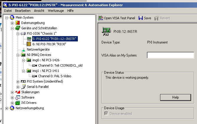
I installed a PXI-6122 card. The device is listed as "Device is working properly" Max:
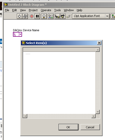
Now, I want to select the device to a constant of the device in LabVIEW 2010, but is not listed there:
I guess it has to do with how MAX recognizes the PXI card, see previous announcement.
Does anyone have an idea how I could make this card works and selectable in LV?
The problem has been resolved by the NI DAQmx developers:
Thank you very much!
-
Triggering off the coast of beginning of Pulse Audio in question DAQmx...
Hi guys,.
First of all, it is more a matter of software than hardware, so I didn't post this specific question in the multifunction DAQ card...
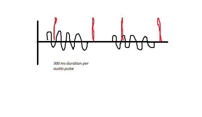
So I'll try to trigger an acquisition finished off the start of a pulse audio, however I have audio sync issues, due to the fact that it can be started before my VI runs. As noted below, the audio is generated and pulsed for 500ms on and 500 ms off the coast, and between these periods, a digital pulse is generated this way (shown in red). I have a problem to stay synchronized, due to the fact that I samples finished for 1 second of a data value, and if the USE EEG is faster than me, I can catch the pulse audio at Midway, rather than at the beginning.
I'm trigger analog outboard of a sound signal of 50mV and capturing two audio channels simultaneously and consistently captures 3 digital channels when they receive the trigger of the beginning of analog input trigger reference digital edge. If digital are slaves and audio is the master in this configuration. The point of this is to get a delta timed material at the time rather than use the timestamps of windows.
As I said, I use an Analog Edge Trigger Start to start my purchase, what triggers the digital task Digital Edge Start Trigger to start as well. How can I make sure that I start at the BEGINNING of a new pulse audio if I get out of sync, I can't understand this logic... Analog edge goes off just when it goes to the specified level, but maybe it's at half way through the 500ms pulse, so this is my problem...
I need to be a trigger to start because I do 55 000 this test iterations in a QMH Prod/consumer model and need relaxation to be redeclenchables and start-up is only redeclenchables.
The variability in timing you see at points 2 and 4 somewhat dictate against the possibility to set up a re-triggering precisely timed by the hardware configuration. I think that you need to abandon the idea of making repeated sampling finished back to back and switch volleys in a mode of continuous acquisition and treatment.
To help with this, I aim to capture the moments of digital via meter rather than DIO pulses and be ready to give up the acquisition rate noise much (if necessary) given that you said that your main concern is to distinguish between ON and OFF.
I must configure the counter to use the Digital pulse as a sample clock and use the sample clock signal HAVE the "time base", i.e. the signal which the edges will be counted and buffered in memory. This will give you 2 samples per second instead of 5 M and the values of the counter at these sampling points is the index in your AI data which occurred impulses. Pretty neat and clean. Just be sure to start the task of counter in front of the task to HAVE it.
-Kevin P
Maybe you are looking for
-
need to remove an application in win xp. did not work with the Elimination of programs. failed to uninstall some programs.
-
Windows XP on the laptop, but saying Windows 7 Build 7?
My laptop runs Windows XP Edition family, but at the bottom right of the screen is, Windows 7 Build 7600 this copy of Windows is not genuine.the laptop never had other copies of Windows is installed, this message just came at the start of the laptop,
-
all-in-one want 27 hdmi connection
nine out of the box. I can't get my hdmi to work. any suggestion
-
My Dell D520 microphone does not work
IAM using 8 Microphone Pro on my Dell D520, but external windows does not work, what can I do guys?
-
Why can I not use "play to" listening to music in network folders?
This really should not be this difficult. I have a router (asus RT-N66U) and a drive hard usb connected to it (WD Mybook). Hard disk is full of files mp3 music. I use WMP12 to play that music on any of the computers connected to the network (Win7 an