Digital processing in real-time or on FPGA?
I am new in time real and FPGA (I got the starter kit 08 - 2012 but I just got all the programs installed a few days). I saw in the LabVIEW FPGA module and LabVIEW modules in real time, we can use functions of digital processing of the signal on both. In the case, a function is supported on both - what wil be some criterion to decide which one we should go with?
Much of the decision will probably depend on the type of signal that you are handling. If you have not worked with or the other, real-time is probably easier to start with. On the other hand, FPGA can be better if you look more advanced working or processing on a point by point basis.
There is a part of the community OR which is dedicated to the analysis and signal processing. I would like to look at some examples and discussions over there to get an idea of what your application can cause.
https://decibel.NI.com/content/groups/signal-processing-and-analysis
Tags: NI Software
Similar Questions
-
I have 2 questions related to LabVIEW Real-time. I'm using LabVIEW 2010 Service Pack 1. We have a PXI-8186 controller running the embedded real-time.
(1) I have my software written to communicate using TCP/IP. The real time software runs the listener 'TCP create' then the 'wait on TCP listener"to look for the connections of the computer. This works well in the LabVIEW project. I then build the executable and deploy it in the system in real time, set up to run during startup. I put the target name to be my program name "Test program.rtexe" rather than "startup.rtexe". I don't know if that makes a difference. I saw the other files in the startup folder of the system in real time that have been named something else. My questions are: the name possible no matter what name we want and the system in real time all programs contained in the startup folder is running or is there another method to specify the programs to be executed?
(2) is there a way to monitor or to see what programs are running on the system in real time? As the the Task Manager on a windows system. The reason I ask, is that after I restart the PXI system and without using the program of project, I can't connect to my test program running on the system in real time. I don't know if the software is running on the system in real time, is it established that the network interface which it was assumed, etc. to determine why I can not connect with him. Any help on various methods to determine if the software actually runs would be useful.
Thanks for any help you can give.
Bill
Finally found the problem.
It would seem that, at least in the 2 controllers shipped we have there, controllers have a flag in the BIOS that allows you to disable the file to begin execution on the system in real time. Once I put the flag on the 'NO', everything works. The flag is named:
'Disable the boot VI' tab 'LabVIEW RT"in the BIOS.
It is a good option if the boot VI is damaged or was not debugged prior to deployment.
-
[fpga] Faster communication between FPGA and host in real-time
Hi all
I received a card FPGA NI FlexRIO (SMU-7965R) installed on a chassis PXI (SMU-8135 embedded controller). I have an FPGA program to 40 MHz, and I use a real-time program to read a particular variable of FPGA on a regular basis. I do not stream. All I need is to get the most recent value during each execution of the loop of the program in real time (hence, DMA FIFO is not a good option). I am aware that you can read the FPGA indicators in the host program (real time) using the FPGA read/write control function. I used this feature to read a certain variable of indicator FPGA, as shown in the screenshot. The RT program takes 100 micro-seconds (10 kHz), which is not fast enough for my application.
Is there a faster method to read the latest FPGA data, or the program shown in the screenshot can be modified to reduce the time of loop RT? Any help would be greatly appreciated.
You're talking about an RT target a sitting in the RT himself FPGA card? If so, have you tried without the IP address of the target. See this thread to see why that would make a difference.
-
Structure of the timed real-time event loop does not work
I'm a new user for LabVIEW. And I've encountered a problem that frastre really me! Hope someone can help out me. Thanks in advance!
I just want to use the structure of the event under timed loop, which is important in my extrmely design.
However, this works very well in my computer (without connecting to the FPGA).
Once I connect it to the FPGA, then I can still run but there is no response!
My file is attached. Please someone help me!
Looking forward to your answers!
The FPGA runs headless. Structures of the event won't work. What you need to do is to have an application on your host computer when the user presses a button, changes a value, etc.. This event should send a message via TCP/IP for code that runs in real-time environment. Then the real time environment should attribute to the desired value a control on the FPGA.
As a general rule, programming real-time with FPGA has several layers.
(1) host-> handles interactions with the user code and communicates the code in real-time via TCP, UDP, etc.. Displays the user sent by RT controller data.
(2) code in real-time-> tracks headlessly. Manages host code messages, processes the data of FPGA, communicates with FPGA much as the host code communicates with the code in real-time
(3) FPGA-> no acquistion and passes through PEP in the RT
The first thing you need to do is to understand the architecture and how all these pieces of the puzzle work together before you throw things down on a diagram.
-
difference between the real time module and module fpga
Hi experts,
I was wondering if someone could tell me the difference between the FPGA and the module in real time (in short).
My understanding is that the FPGA module facilitates code LV that can then be designed for the specific advice of RIO, I have used this a bit in the past.
The real time module, I'm a little more unsure about, all I know is that it allows the creation of a 'real time' i.e. deterministic environment.
My request is this: I wish I had several control loops running on two tables of RIO, with the host PC mainly used for recording data and user interface. I see that I have no need of RT on the host (Win XP should be good).
Do I need the RT module?
You are right. In the scenario you describe, you won't need to LabVIEW RT. LabVIEW RT is used to create a deterministic execution on specific targets for intel such as the PXI-8106 and PXI-8108. You can still use strings and floating point on RT.
-
In almost real time image processing
What is the best way to implement almost "real - time" treatment of image with two usb cameras? Capture, process, showing results and then capture, process, etc. until I chose to stop the program. I use LV with vision development module 8.6. What function can I use to capture the image?
With LabVIEW 8.6, you can get the driver NOR-IMAQ for USB cameras . It's really similar to the other drivers IMAQ, but examples are provided in this knowledge base. To use several cameras, you will use just two copies of the screws.
I'm not sure if you need more information than that, but let me know if you have any more specific questions, with which I can help.
-
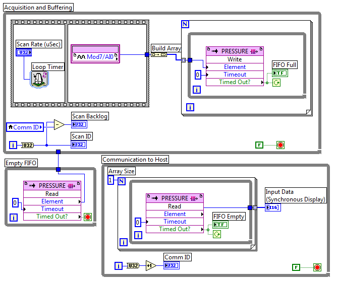
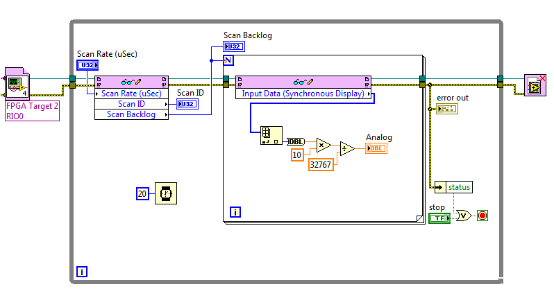
FPGA FIFO real-time error-61206
I used this white paper as a base for my code. My FPGA look like:
And my time real-time (RT):
I am using a cRIO-9022 and now just trying to get the foundations buried for my project. The problem is that the side FPGA works well but environmental RT takes maybe 2 or 3 seconds and close with this error:
Code:-61206
Source: Read/write in FIFO_pressure_RT.vi control
I have not dealt with the FIFOs in LabView before I have no idea what is the cause. Any ideas?
Thank you
Logan
What version of LabVIEW are you using? In LabVIEW 2011, if orders or the lights on the front of the FPGA had a jump of line or transport back in the label, the question would be filling in the read/write control node, but you would see this error. It seems that Input Data (synchronous display) probably has a newline character that could cause this. That the problem has been solved in LabVIEW 2011 SP1, but what happens if you remove the line break and recompile the FPGA VI?
-
Hello
I have a compact rio, which has a 4 way frame this chassis is the three modules of ni9234, they are related using FPGAs for application in real time, then using shared variables in the low-speed loop associated with a slave modbus to communicate with the domain controllers, the nor 9234 accelerometers linked to them with option ac coupled iepe on c modules , my problem is the real-time application seems to work well even when power loss occurs it restarts without problem and the fpga written hard disk portable bin files very well, but without an accelerometer connected I get readings of low noise as soon as I connect an accelerometer to one of the outputs 10 it just goes to a fixed number (0.03125) as soon as you unplug it again He returned to readout noise, I ran a scan on the modules and get only a spike when I connect or disconnect the accelerometer, I tested voltage at the pins on the module and I get 22 volts CC which makes it more likely that the material is not the problem, but software is perhaps the cause to hang up, I join the project and files for your perusal. I also realized a new project which, in mode directly linked scan has the module entry in the shared variable and the scenerio even once again. Help would be appretiated.
Thank you very much
Jason
Whren using waveform with the 9234 acquisition, we recommend the following FPGA and RT model.
http://sine.NI.com/NIPs/CDs/view/p/lang/en/NID/209114
It can be extended as a datalogger with:
http://zone.NI.com/DevZone/CDA/EPD/p/ID/6388
or using shared variables combined with the analytical engine
http://zone.NI.com/DevZone/CDA/tut/p/ID/9851
The FPGA in all this, as well as the framework of RT have used successfully by 1000s of users. I recommend giving these a try.
-
On a Linux operating system, what tools need to developed a real-time application communicating with FPGA?
It is not unclear to me by reading the documentation on the website OR tools or drivers should I install on a Linux operating system in order to develop a C++ real-time application (that interact with FPGA) which will take place on a sbRIO-9651.
Is this possible at all?
Thank you
Michel
Everything works very well with an FPGA VI, compiled with LabVIEW FPGA 2015.
1. I have installed Eclipse on CentOS 7 with cross-compiler found at this link:
Compilers C & C++ GNU for Linux ARMv7 (Linux host) 2014
2. I also install a debugger crossed to debug application c / c++ remotly. Once on the page go in the section "Linaro Toolchain for Cortex-A" and download the second link linux "linaro-toolchain-binary (big-endian). The binary gdb is in there, so you must point towards him in the Eclipse debug configuration:
3. I installed the linux drivers from NOR-RIO 15:
4. I was able to program an application to c / c++ opening and running a LabVIEW FPGA Bitstream in a few steps:
Example of API Interface FPGA C OR real time Linux and Eclipse
Michel
-
Debugging on a real-time target - deployment issues
Dear community,
After RT my 9651 sbRIO module wiring code, I do tests to check the intended functionality. For this I start my main VI who deploys the code on my SoM and I can happily move forward with my debugging session.
Sometimes, however, while in the process of deployment, I get an error saying:
[VI - name] .vi loaded with errors on the target and was closed
When I open the VI it has no errors and the VI should work a fine might think.
My solution was so far of the VI, just open move the wires and terminals round, re - save the VI and this is the deployment works.
This trick worked for a while, because deployment error ca occur arbitrarily on different VI making debugging quite cumbersome.
I then went ahead and just run the wrong VI in RT mode by moving terminals and structures around to get the VI runs in mode debugging, but it is very time consuming.
Given that 3 people working on this project and we use git-subversioning I also do not want to "touch" each time just screws for the debugging session will without actually modifying the feature.
Has anyone encountered a similar experience or perhaps found a magical setting to avoid this subject a lot of time?
Hello
If solutions already present Spex does not do the trick for you, clearing the cache of the compiled object can help.
For more information, take a look at the following link:
Why my screws are loaded with errors when it is deployed at my target in real time? -National Instruments
http://digital.NI.com/public.nsf/allkb/7F6502FF0560FA9086257EB3005B13BAConcerning
Alex
-
Hello
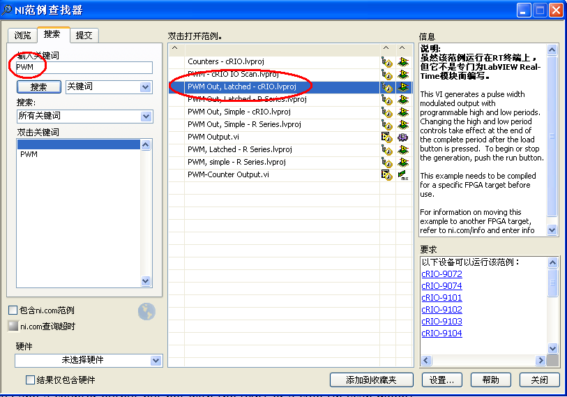
Currently, I am trying to control heater with a relay of 9481 operating module real-time on a cRio. According to some brochures NOR the 9481 a capacity PWM (not 100% sure of this). Is this true? How can I get access to the content of the PWM feature?
I did it with the help of a compact data acquisition and output of counter, but not with the 9481 or a cRio (in scan mode).
And if it is not possible, what would be a better route to go if I have to use the working 9481 one on a cRio?
Thanks in advance!
-TJ
Hello TJ
First of all, the NOR-9481 itself cannot produce the PWM, but it can run in cDAQ. Because the cDAQ chassis will end the PWM of the book part.
Now that you use a cRIO, all labor PWM, you must complete your self (the 9481 cannot work as PWM in Scan mode), you must use the FPGA.
There are some examples that you can find in the finder of the example
Just write the digital output on the port of 9481
-
Controller time real-time FieldPoint or Ethernet interface
Good afternoon
The first feature listed on the PS-2000 product page is:
- Stand-alone embedded real-time controller or on PC distributed i/o Ethernet interface.
-
Analyzers of vector signals OR, in real time of tektronix and tests EMC spectrum analyzers
Normal
021
fake
fake
fakePT - BR
X NONE
X NONEMicrosoftInternetExplorer4
/ * Style definitions * /.
table. MsoNormalTable
{mso-style-name: "Table normal";}
MSO-knew-rowband-size: 0;
MSO-knew-colband-size: 0;
MSO-style - noshow:yes;
MSO-style-priority: 99;
MSO-style - qformat:yes;
"mso-style-parent:" ";" "
MSO-padding-alt: 0 cm 0 cm 5.4pt 5.4pt;
MSO-para-margin-top: 0 cm;
MSO-para-margin-right: 0 cm;
MSO-para-margin-bottom: 10.0pt;
MSO-para-margin-left: 0 cm;
line-height: 115%;
MSO-pagination: widow-orphan;
font-size: 11.0pt;
font family: 'Calibri', 'sans-serif ';
MSO-ascii-font-family: Calibri;
MSO-ascii-theme-make: minor-latin;
MSO-hansi-font-family: Calibri;
MSO-hansi-theme-make: minor-latin;
mso-fareast-language: EN-US ;}1. how to work if vector performance of or
Analyzers of signals compare to Tektronix real-time spectrum analyzers?2 can you emulate Tektronix FFT
processing overlapping?3. is it possible to use vector of NOR
Analyzers of signals of compliance EMC and/or test preconformite? Is there some
companies use it successfully? Need a special or custom software?Thank you
Hi emc2006
I'll answer your questions separated by your topics:
1 - What is the factor that you want to compare between these two products? In the link below, you will find the performance of the NI PXI-5660 RF Signal Analyzer system.
2. you can develop this feature of programming in software Application development, i.e. of LabVIEW.
3. Yes, NI´s vector signal Analyzer could run preconformite or EMC compliance analyses. In the same link below, you will find in the subdivision of Applications.http://zone.NI.com/DevZone/CDA/tut/p/ID/4298
Concerning
Napoleao
Application engineering
National Instruments -
Rotary decoder in real-time and 'pulse shifter '.
Hello world
I'm putting in place a rotating decoder for use as a shifter of pulsation by labview real-time.
Basically, this means I have two input channels (ttl-legumes, ~ high 20us) rotary engine. A channel contains a pulse at each CA (angle cranc) ° up to 12 kHz (increment). The other channel contains a pulse every 720 ° CA (the charge cycle, BDC_cc low break-even point). With this information a pulse to be generated on an output also channel ttl (high), which triggers my setup of measurement. This impulse must be moved in a programmable relationship to the entrance of BDC_cc, which aims at a table of regular measure.
I got it running by streaming the channel of BDC_cc until a rising edge is detected, then count the edges of increment to the designated trigger point and then generate a pulse on the output channel. The problem is that the late 70-120us exit trigger. In short it's too; a maximum error of ~ 20 is acceptable. Digital channels appear to work faster, so I put discarded Counter-based acquisition.
I'm quite new to LabView, so I'm sorry if the answer is obvious...
My purchase setup consists of:
PCI-MIO-16-1
BNC-2120
LabView 12.0
Max 5.3.1f0Widows XP
This configuration seems to exclude some options Labview offer, such as the external digital acquisition sampled or externally triggered by the acquisition in the base. A manual interpretation of analog inputs is way to slow.
I have attached my working version.
Any input appreciated woud...
John,
I only have a minute right now, but think I can play with a device simulated tonight or tomorrow.
I'm quite sure that there would be a clean solution clocked by material if you use a series M or X-series
Council MIO, but the older generation counters timers on the set of the E series do support everything which
You need. It's been a while since I had to rely on this generation of hardware.
I think the basic approach is to use the lunatics of angle as the clock pulse train that defines the
delay time of the pulse you want to generate. You could be "Timer" the pulse based on the real
angular position, helping you synchronize to a specific angle of crank. The question is whether and how E-series
counters of takes to support the generation of pulses triggered (or redeclenchables). If they are not, I would say that you consider
get new hardware DAQ which support this kind of trigger and you give a very precise pulse
implementation.
-Kevin P
-
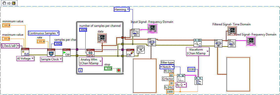
Continuous data acquisition and real-time analysis
Hi all
It is a VI for the continuous acquisition of an ECG signal. As far as I understand that the analog read DAQmx VI must be placed inside a while loop so it can acquire the data permanently, I need perform filtering and analysis of the wave in real time. How I implemented the block schema means that data stays int the while loop, and AFAIK the data will be transferred on through the tunnels of data once the loop ends the execution, it clearly isn't real-time data processing.
The only way I can think to fixing this problem is by placing another loop that covers the screw scene filtering and using some sort of registeing shift to transmit the data in the second while loop. My question is whether or not it would introduce some sort of delay, and weather or not it would be supposed to be the treatment in real time. Wouldn't be better to place all the screws (aquicition and filtering) inside a while loop? or it is a bad programming practice. Other features I need to do is back up the data I na file, but only when the user wants to do.
Any advice would be appreciated.
You have two options:
- A. as you said, you can place the code inside your current while loop to perform the treatment. If you're smart, you won't need to put one another while loop inside your existing (nested loops). But it totally depends on the type of treatment that you do.
- B. create a second parallel loop to perform the treatment. This would be separate processes to ensure that the treatment is not obstacle to your purchase. For more information, see here .
Your choice really depends on the transformation that you plan to perform. If it's much the processor, this could introduce delays as you said.
I would recommend that you start at any place in the first loop and see if your DAQ buffer overruns (you can monitor the rear of the buffer during operation). If so, you should decouple the process in separate loops.
In what concerns or not ' it would be considered as real time processing ' is a trick question. Most of the people on these forums say that your system is NEVER in real time because you're using a desktop PC to perform processing (note: I guess it's the code that runs on a laptop or desktop?). It is not a deterministic systemand your data is already "old" by the time wherever he leaves your DAQ buffer. But the answer to your question really depends on how you define "real time processing". Many lay it will set as the treatment of 'live' data... but what is "actual data"?
Everyone was able incorporate a PS-2000 as an Ethernet on PC distributed i/o interface? In other words, have the PS-2000 as a FP-1600 Act?
There are some discussions forum discussions that dance around the subject, but I found no really one who responds to her.
Thank you
Ed
Hi edlad,
After playing with a FP-2010 for a while, I think you need to install LabVIEW Real-time on the controller to make it work, even though you are technically not to use it because you are not running a VI/executable on the controller. Regarding your problem with the installation of LabVIEW 8.5.1 on a PS-2000, it is disturbing because it should not be a problem that at all. In fact, I have personally been able to install LabVIEW 8.5.1 on many FP of the 2000s. For that matter, I suggest reformatting of the PS-2000 of MAX and try again.
ThinkG: Regarding your question on the use of a PSC-2220 to connect with belvedere, I don't know because the support of Lookout is managed by our subsidiary in Shanghai by e-mail only. However, I don't know that you can use this second ethernet port to connect with another network (cFP-180 x) FieldPoint module using the FieldPoint drivers. Here are some good articles about this configuration knowledge base. I hope they are useful.
http://digital.NI.com/public.nsf/allkb/F602F6F1B243282686257495007695BB?OpenDocument
http://digital.NI.com/public.nsf/allkb/67F94BB93BCE32CF86257367006B3659?OpenDocument
Thanks for choosing National instruments.
Aaron Peña
National Instruments
Technical sales engineer
Maybe you are looking for
-
Compare two columns and get the percentage of cells that match
Hello I'm looking to take two columns of data from different tables in the same document, which should have a high enough percentage of boxes and have another cell tabulate the corresponding percentage. I can the of seem to figure out how to do this,
-
Goodmorning, I VBAI have experienced lately, and I have a slight problem. When you use a hardware trigger I sometimes have a downtime. My trigger is a 24V signal and my cam is a G201C of Manta (ally). (Look at this message below for the trigger param
-
How to see the level of ink for a dell v515w printer?
Separated from this thread. How to see the level of ink for a dell v515w printer?
-
items still showing on the list of programs in the deleted yet software Panel of the system
problems with microsoft works tried to repair but has so I reloaded the software from the disc. the list of applications in the Panel now two entries for microsoft works and I am unable to remove.
-
Vista SP1 not only installation and no error message
I have a new hard drive and a new install of Vista Home Premium 32 bit. I get an advisory update for SP1. It's a 1.9 MB and after installation it says properly installed yet SP1 is not. The guard update reappear. Any suggestions? Starnge because it's