Digital reading Pulse with PCIe 6509
Hi all
I'm trying to decode an infrared control using the PCIe 6509, but I've no chance that a signal from a remote control. It seems that when I use the VI of change detection, it does not generate the interrupt, but it cannot produce enough it fast to create a template to use with the reading VI Daqmx. Does anyone know if something like this is possible? The idea is to make the PCIe 6509 generate a digital output signal for each key different on the controller.
Thank you!
Kenny
Arduinos are often used. There are a few boxes to software tools out there like LIFA and Lynx. Then you just need a serial port to communicate.
Tags: NI Hardware
Similar Questions
-
Analog multichannel peculiar read problem with PCI-6014 - hardware problem
Hi all
I see some very special behaviors with a 6014 when I do a multi-channel analog playback. I am revamping of existing code to a customer, which implies the passing of the traditional DAQ in the DAQmx. Traditional DAQ does not use a system based on the tasks, my client was in the process of reading clocked by the software for only one channel at a time, depending on what signal was of interest to both. (application is a series of tests on a control PCB who will interface with some hardware, checking the answers and tensions and others)
When I rewrote the application using DAQmx, I created a single task that contains all of the analog inputs of the map (AI0:15). When I am interested in a particular signal, I indexed the channel since the reading chart data. The strings that contain the actual data are 0, 1, 3, 4, 5, 6, 7, 13, 14 and 15. All channels are NRSE.
One of the signals of interest lights AI7.
When I connect the AI7 signal with an oscilloscope, I read 2.5V - which is exactly what I expect to see.
When I read AI7 using MAX, I read 2.5V.
When I read AI7 by itself using a single channel DAQmx reading (i.e. 1 Samp 1Chan or 1Chan N Samp), I read 2.5V.
When I read AI7 simultaneously with all the channels that have a greater number of channel (i.e. AI8-15), I read 2.5V.
When I read AI7 simultaneously with any channel that carries a lower channel number (i.e. AI0-6), I read 2.34V.
?????
For example, if I read AI0:15, I read 2.34V on AI7. If I read AI0:7, I read 2.34V. If I read AI7:15, I read 2.5V. If I read AI7:10, I read 2.5V. If I read AI6:7, I read 2.34V. And so on. Any combination of playback channel which includes results AI0 AI1, AI2, AI3, AI4, AI5 or AI6 during a misreading on AI7.
All channels read because they are supposed to, no matter what channel is included in the job. AI7 is the only one that illustrates this behavior.
I wrote code for the acquisition of data for 10 years now and I have never seen anything like this before. The behavior is consistent. I am sure that it is a hardware problem with the Special Commission that I use. That's the advice of my customer, I don't know when they bought it, but I think they have had for years. I doubt that ever, it has been calibrated.
I guess it's more I'm curious than anything else - what on earth would cause this behavior?
I'll tell my client to replace the card, if really I just asked my own knowledge.
-
How to trigger the camera and light pulsed with PCIe-1427
Hello
We recently bought an acquisition card NI PCIe-1024 and the NI Vision Builder.
I am new to imaging applications and need support to get started.
Application:
We have a camera viewing a scene which is illuminated by a pulsed light source (e.g., a strobe).
We want to use the PCIe-1427 as the master for the outbreak of the camera and strobe light.
The first trigger (Ch 0) transmitting signals TTL to camera to 30 Hz (30 fps).
The second trigger (Ch 1) send bursts of pulses to the strobe light to e.g. 10 kHz. This trigger must only send impulses all other images, so that we can save alternating light and dark images in order to perform background subtraction.
I tried to set up the channels of the trigger and create virtual channels in the measurement and Applications Explorer, but apparently this is not possible.
Since it is an application critical time, I'd appreciate an example vi that sets up the channels two trigger and download managers in the camera to get started on this application. Thank you.
Software of NEITHER: LabVIEW version 10
Materials: Device for the Acquisition of Image (IMAQ) PCIe-1427 driver Version: NOR-IMAQ 4.4 OS: Windows 7
Thank you, Justin.
I'll copy this request to the machine Vision Group as you suggested. I looked at the link sent you me and made progress (limited). I can see on an oscilloscope trigger signals, and the camera acquires images. However, I only managed to do work for pulse trains continuous, not a shots or bursts of pulses.
No need to answer that. Thanks for your help.
Peter
-
Acquisition of fast pulses with PCI-5122
Hello
in your VI you write in a PDM file as a binary file. You want to save in a spreadsheet file or txt instead? Or just have the waveform data available in other datatype in LabVIEW?
The output of Element.vi Dequeue is table 1 d of waveform: each element of waveform is a cluster of dt (double value), t0 (of a double value) and an array of values double. So, if you need get a 2D with all data table (if I understand correctly), you each elemnt of the 1 d of waveform of the index table, extract the double table in each waveform and then built a 2D array.
You can find an example here.
I hope this helps!
Bye,.
Licia
-
I need to generate 3.3 V logic level Digital train of pulses with the NI PCI-6221. Can I change the level of 6221 OR logic output?
The output cannot be changed. 5V to 3, 3V level controllers are readily available (Maxim, I think). As long as the scanning speed (etc.) is fast enough for your pulse train, even 3, 3V regulator would work. I don't know if NEITHER offers a module to condition TTL levels.
-
patrons of pulse with the repetition of 512us scroll 7811 PCI with compac RIO
We can produce a specific impulse of 15 to 30 pulses model (0.5us pulse width and frequency of 500KHz and models are transmissible repetedly with 512us interval) with PCI 7811 compac RIO. I have material but do not find any help in this regard. If some body send a small vi. assistance. I will be really grateful
Yours sincerely
Do you only need determine if the received model corresponds to the sent model, or do you need to store the received bit model whatever it is? Do you need to process the model received on the FPGA, or you can pass it to the host? How will you know if you begin to receive the reason, especially if it begins with a false?
The best thing to do is to constantly read the digital input and write the value to a FIFO DMA, you read about the host, where you can treat them more easily. If you need an immediate comparison on the FPGA, you will have to design an algorithm more complex which is used to determine when the received model starts and it matches against the model that was sent.
-
I hope someone can point me in the right direction and also to clarify some concepts!
Background: I am currently using the box USB-6009 and labview on a laptop to output 2 analog waves. It acts as a waveform(0.5-2Hz) of speed (periodic) for an engine step by step (with a driver) to execute a loop of traffic, and the other waveform acts as a signal short 5V to trigger some imaging equipment. The ability to move or to delay the start time of the wave of 'trigger' compared to the waveform of speed in steps of hail (ms) became a requirement for my experiments. Given the time where the USB-6009 case, software based accuracy was not good enough because I need, and the way I wrote the VI limits my delay/travel at the speed of wave deltaT(30-40ms). I started to look at the USB - M series (portability is an obligation) since some have calendar based on the material, and I could send the signal to a buffer rather than iteratively having read every value of the wave in. It also seems that a digital short "pulse" works better than an analog wave form creating any. Where I ran into some confusion is to determine the requirements of a deterministic way sync the two. I am looking for new hardware. I started by looking at the box USB-6211. However, I ran across a few posts talking about the digital I/o correlated being required to perform vaguely similar configurations, which would require something more like the USB-6221. Since I have probably to the digital output to be on a time scale different analog output, is i/o digital correlated required? If not, would the 6211 work?
Just to be clear, I need the periodic waveform and relaxation to be constantly in phase (anywhere, 10 minutes to several hours). Then be able to move the pulse +/-1ms (minimum) and repeat. I can justify the most expensive device if necessary, but I don't want to get something I don't need.
I have attached a figure (not not to scale) of what I am after, in the likely event that my explanation was not too clear.
Thank you
Gabe
Hi Gabe,
The 6211 did not buffer IO digital as some of our other devices. However, there are two complete meters on the 6211 which can be used to perform a generation of pulses (pulse or continuous pulse train - you can output a pulse train using two counters finished). You can take a look at the section Applications of meter output x 621 manual for more information.
What it sounds like, the 6211 will do what you need for the following reasons:
1. the AO of the 6211 lines are buffered and can be clocked up to 250 kHz per channel (in contrast to the 6009 using AO NI by SW).
2 the 6211 counters can be used to generate two pulse based on a basis of time of 80 MHz (12.5 ns pulse width and resolution time). The 6009 does not output meter.
(a) if the two pulses must be on the same line, you must configure a task of generation of pulses finished' (this example uses two meters behind the scenes).
(b) if both impulses are on separate lines, then you can use a task to counter separated for each line with a different initial delay.
The 6211 does not supported clocked generation of digital signals (e.g. 100010101110100) but if you just need to generate impulses so that's precisely what the counters can be used to. I think that's where all the confusion, but seems like the generation of digital signals should not be necessary for your application. Trigger the counter outputs out of the trigger to start AO and adjusting the parameter 'Initial period' should give you what you are looking for. Don't forget to start the tasks of meter in the software before the tasks of the AO (if they are armed and ready to go before the start AO is sent).
I hope this helps, don't forget to post if you have any questions!
Best regards
-
How to count the pulses with digital input on 6351
Hi all experts in Labview,.
I just got my USB x series 6351 and it works fine, but I certainly lack of labview skills to use it to its full potential.
I would like to read digital pulses with several digital inputs and count the number of pulses each T interval in time. All impulses that I entered on any edge of the clock are not synchronized and can occur at random times during the tests. Basically I have an oscillator of square waves can I modulate the frequency. I don't want to use the meter as inputs as I'm limited to only 2 entries (if I use the option 2 input meter for metering of pulses or frequency). The input frequency can range from 0-1 kHz and goes 0 - 3V. So not too fast, and I shouldn't make too many mistakes trying to get the count of pulses and then back out the frequency in accordance with article ni.com on counters.
I would like to read the 8 digital input channels and get the number of impulses for each channel. I searched high and low for help online but can't find examples that have been useful. Anyone have any ideas on how to go or direct me to a resource? Thank you very much in advance!
Are you worried about getting the number as a physical operation timed? It would be nice to acquire a digital waveform and then postprocess on it to detect how many events took place? I've attached an example that shows how you can accomplish this. It reads a digital waveform and then uses a detection of crete VI to determine how many pulses occurred. Should be a few adjustments to your particular signal. The VI I use seems to count events twice (probably count each edge), so counting it gives should be reduced by half in order to work.
-
Acquisition of Digital Data Output: generate a pulse with a specific width (depending on time)
How can I generate a digital pulse with a specific width? I was not able to find examples online. Thank you!
With the USB-6000 - essentially none. He has only digital software programmed according to i/o. on your system, you may be able to generate impulses at speeds up to a few hundred Hertz, but there will be a considerable amount of timing jitter. Tens of milliseconds can be common and even longer variations may occur occasionally.
Please indicate which are the times for your impulses, so someone may be able to provide recommendations specific to your needs.
Lynn
-
PCIe-6509 register level programming: cannot access the ASIC slave
I'm running one of the RPL (boardBringUp.cpp) examples using the RTX operating system.
The program crashes when I try to access the STC3 ASIC "slave". When I try to read the signature ASIC slave when I try to access the OID or ports starting at port 6 which is the first port on the slave STC3.
Any ideas on what to try?
I just noticed that the RTX operating system layer was not modified to work with the PCIe-6509. The layer of the operating system allocates only byte 0 x 40000 for retgisters of the card. The problem is that the notebook for the STC3 slave register is 0 x 40004, the origin of the problem. You can change the osiUserCode.cpp to allocate more memory to bar0. I recommend 0 x 80000.
Thank you
Steven T.
-
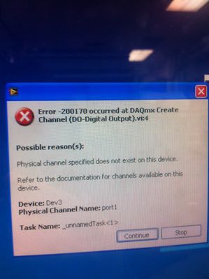
200170 with PCI-MIO-16XE-10 error
Hello
I work in a lab and one of our machines had to be updated in Labview 8.5 in 2011 to implement a new box to tools. I changed any code and have not yet implemented any changes for the new box to tools. In addition, the program worked before the upgrade. Now, when I run the program I can not run a test because some parameters that indicate that everything is ready are not fulfilled, these parameters are read by the PCI-MIO-16XE-10 (Dev3). Then, when I stop the program I get the following error:
I use the DAQ assistant to read a Digital-In.
After you have upgraded, I assume this problem is either bettween compatibility 2011 (probably DAQmx) and the card PCI, or that the driver for the PCI card does not work right (even if it says that the device works properly on the 'Self Test' max).
While the above issues likely causing the problem? The PCI-MIO-16XE is only compatible with traditional and not DAQmx? How can I check to see if it is set up right if it is compatible with DAQmx?
Thank you
Link
The problem is exactly what this message says. The device has only port0. He could never have worked with port1.
-
Detection of changes in PCI-6509 missing first data entry
Hello
I have two 6509 cards in separate computers, connected to each other. I use six lines, with one channel for each line, to send signals between the two boxes.
I used the driver NOR-DAQmx 8.0.2 on SUSE Linux, coded in C.
Starting by examples of digital I/o that I did a card pass in four lines and the other card received the signal, using the detection of change on the falling edge only, with the lines reversed.
To send a signal it took the value 1 on this line, using digital lines of writing and then set it to 0 using the same function.
If I send 4 signals, apartment of 100 ms, 1 on each line. The recipient will detect all four edges of falls, but the function of reading digital lines (in the recall of events highlights registed) returns zero for the first detection. I read only one sample of each line. Once that happens all seems fine.
I read that more than a sample for the first digital reading for function call?
What I have to do my signal longer, for the moment it comes to 150us? I can do this with an expectation in the code. I can afford it to streatch for about 1 ms, but it's always with this kind of treatment.
Is there some call the initialization to get the driver to initialize the internal memory or something? (Maybe it's my wrt slow code, but I don't see how, there is almost nothing.)
Thank you
I think we arrived at the conclusion that this card cannot detect as close as 450ns interruptions. The API does not quickly that detect enough them between the interruption and the call to read data lines.
It seems that we should have brought a card counting rather than a map of interruption.
-
Computer does not start when PCI-6509 is installed.
We have a "shoe box" Advantech (System specs are listed below) and try to install a digital I/o card of National Instruments PCI-6509. Once we install the digital IO card, the computer will not start. The computer does not even a MESSAGE. We know that the digital I/o card is functional because we ran the same card on several different machines. We also tried the card on other Advantech computers with the same brand and model without success. What should we do to get the card working on Advantech computer?
Advantech computer scpecifitaions:
Pentium 4 with backplane passive 256 MB DDR memory, Windows 2000,.Thank you for your help,
Tim Elsenbroich
Software engineer
Wisconsin electronic systems, Inc.
Phone: 262-554-1211
FAX: 262-554-1797
E-mail: [email protected]We hung a spare ATX power supply to backplane of the computer, the computer booted right up and the PCI-6509 worked perfectly. I contacted the manufacturer of the computer and am waiting for prices on ATX supplies getting in our computers instead of the TA.
Thank you for all your help.
-
Triggers the analogue output with PCI-4461
Hello
I'm trying to generate a signal of analog output triggered with a card PCI-4461. First I tried to use the feature OR DAQmx 'start analog edge' with the way analog input AI0 as the source and the channel analog output AO0 as task. After it gave an error that I tried to use the NI DAQmx 'start digital dashboard' function with PCI0 as source and channel of analog output AO0 as task. It ran, but did not produce any output. Now I wonder if I can use the trigger analog or digital of the PCI-4461 to all of the output.
Thanks for support you,
Pribislav
Pribislav salvation,
you still have this problem? I did exactly the same configuration (power play) and it works fine on my system. The PCI-4461 does not support analog triggering, that's why this error occurs.
Kind regards
Michaud
-
LabVIEW 8.5 / DAQmX 9.3 / USB-6211
I did not want this post without trying everything I could think of, but after a week I'm ideas.
I create 2 config Subvi, read analog and digital tasks. When I run the main vi (digital playback problem), it runs without error until I have call the config.vi. Then, it throws an error-00088 (invalid or unassigned task). I ran with the tracer on (bulb) and the digital reading (where I have indicated in the block diag) is the area of the problem. The error is 'OK' to go in, "-200088' coming-out.» I have defined the task until it's called, but he seems to think that I don't have. I'm sure that I made a mistake of workflow, but I can't find it. Any ideas?
BTW, there is a file of menu RT with this project that this forum doesn't let me download. I hope that the vi can work without it she
is a choice of menu that calls the config.vi
One thing I immedaitely see it is that the structure of your event in the Subvi makes void the task because you have "use default if Unwired.
Maybe you are looking for
-
When I click to open a new tab, the new tab does not open. Some web pages open new tabs correctly. I tried safe mode and new tabs will open correctly in the corresponding mode. I use Norton to anti-protection against viruses. What is Norton causing t
-
I get an email with the name signature commercial \phone # ect ect... real basic stuff. When I do without HTML there is in formal, but VERY light... I only hit HTML to make it bolder\darker...but when I type HTML everything appears in a single straig
-
All-in-one Deskjet 2540: reset password WiFi live with security enabled
Good then everything was going well and everything until I one day decided to enable security of the printer and change direct wifi password. It was fine, because I instatly reconnected with the new password and never had to kick it manually again. t
-
Hi all. I have an OLD NI instrument Simulator. It is so old, that I'm not still able to use the NI instrument Simulator Wizard. I called for the support and the technician was more useful however, whenever I run the wizard, it opens and alarm that re
-
I have an E260 that I can't recognize all my music, I have a c200 series and an e250 that works very well no clue. When I sync the same songs at the c200 and e250 they work when I sync the songs to the 260 I get the message I need to sync for music