DIO
Hello
I'm busy with the NI 6509 USB device simulation, my goal is to configure 6 ports (48 lines) as input, and the other port 6 as output and display the result on the front panel, as an array of Boolean 1 d of 48 read and write lines, where I can switch the switches to write data is 1 line or port or 48 all lines at once and read the result on the Boolean LEDS or 1 line or port, or all the 48 lines at a time.
I am aware that I have the USB-6509 physical device to read the entry by connecting the output to the input by using cables or accessories that shipped with, but my only worries were:
(1) when I ran the simulation I can write values as binary numbers, but in what order are they written to ports or bloodlines, it is first LSB or MSB wrt to the line 0/0 Port device.
(2) because the outlet may not be connected to the input of thought software, the values written will be the same, or read in the same order (MSB first etc) during a test physically because when I ran the simulation, the entrance was just read (counting in binary values left most bit first of all, from line to line on a per port basis.) Is it by default a counter entry when there is no hardware connected and if that is the case why he should count or read values through three ports (line0_32 etc) IE it relies on all ports of three at a time for example [11111110 11111110 1111110] to 255 decimal. If it should not be [11111110 00000000 00000000] and then rolls over nests port if the first port is full with [11111111].
(3) is it possible to write or read from 6 ports (48lines) at a time and see the result in a 1 D array (48 LEDS 1row) boolean or otherwise because in the VI/o device, you can select a maximum of 4 ports (lines0_32) at a time and if you have read/write and display more than 32 lines both how you do it.
Why can't OR add a polymorphic VI of read/write which can read or write up to 96 lines in the case of devices OR-6509.
In any case thanks for reading my boring long doubt, I'll appreciate any response.
Rgds
Paul.
Hello
Thanks for the idea.
What I meant by 'Device of e/s VI'; is the physical "DAQmx channel" function on the front panel, where you can select a line or port or the lines_0-32, etc. to be entered or output of a device.
I was tyring to say you are limited to the fixed option to Select in the drop-down arrow a maximum of 32 lines to write or read at the same time , but it is possible to read/write 32-bit morethan by selecting a line or port in turn to amount to more than 32 lines.
In other words, there are a no options to select or configure lines_0-48 or 96-lines_0 to perform operations of read/write in a move even if it can be done by selecting each line or port or a maximum of 32 lines at a time.
Rgds
Paul
Tags: NI Hardware
Similar Questions
-
HP Pavilion m6-1045dx: update the bios y dios UN error
Update the bios y dio UN error desde the pagina driver busque bios desde php the instale y y is reinicio pc sola y is quedo pantalla negra pero el equipo lights are una portatil HP Pavilion m6-1045dx
Ayuda than devo hacer para las dress bios?
@David- 100
Thank you for visiting our English HP Support Forum. We are only able to respond to messages written in English. To ensure a fast response, it would be desirable to ask your question in English. The following links are here to help you if you want to post the following language Forum.
German: HP Kundenforum
Spanish: Foro of HP users
French: Forum users
Portuguese: Forum back HP users
Chinese: 惠普个人客户支持论坛
Korean: HP 지식커뮤니티Thanks for your understanding
-
Hi guys!
I'm working on a project where I want to control a motor dc with VirtualBench and LabView.
I have the engine connected to a H-Bridge motor, so I need to send 3 digital signals from the DIO VirtualBench to H-bridge.
With respect to management, I figured out, but now I need help to get a PWM signal to one of the DIO pins.
I can generate a PWM of the FGEN but do not know how to export to a DIO PIN.
I can also generate a PWM with the Express-> entry-> function Generate signal in Labview. But I get an error when you try to write this signal to pin.
Or is there a way smarter or easier?
Help, please!
/ Christian
The digital i/o pins are supported as the SPI, I2C, static DIO (timed by the software) and exports of MSO Trigger or FGEN signals start. There isn't any feature PWM/meter.
It is not a way to generate a PWM signal real on the DIO pins, nor can you give a digital waveform to dig write. From the FGEN might be your best option here.
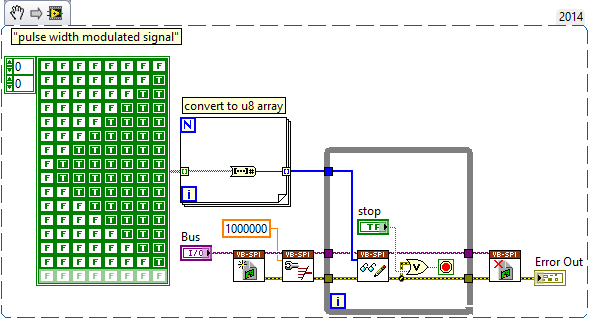
Another possibility might be to use (ab) the functionality of mastering of SPI. The following VI generates a modulated signal of pulse on dig/1 (MOSI) width. It will also generate signals on dig/0 (CLK) and dig/3 (CS), which may not be desirable, and you will have "gaps" between each call to read write of SPI.
-
HS tutorials - DIO / guides / examples? SMU-6544
Hi all
Is a repository for examples of HS-DIO VI available? Are there tutorials? I use a HS SMU-6544-RIO and want to use the generation of static and dynamic signals. So far, I've had a few basic features, but often I'm stuck. For the RIO or DAQ system it seems to be a lot more available resources. Also I couldn't find examples installed with HS-DIO drivers on the local computer. What is a good starting point? Any help is appreciated. Thank you!
Thank you for your patience. I talked to my friend of NOR who pointed me to the right direction.
Examples can be found here:
Open-> examples and navigate to hardware input and output->-> NOR-HSDIO modular instruments and devices
Source:
http://zone.NI.com/reference/en-XX/help/370520K-01/HSDIO/using_ni_hsdio_in_labview/
Hope this can help others in the future.
-
I have a PXI - 6040E DIO P0.0 (52 PIN) port is hooked up to a module OPTO - 22 G4ODC5 (TTL Input). When I run DIO Port COnfig.vi with map direction line the value - 1 (all the value entries Digital Out) it lights up all the inputs(PO.0-7). When I turn actually WE DO using DIO Port Write.vi the, it turns OFF. Tried to reverse the line maximum work don't wilt. All entries?
Hello lilocomotiv,
The behavior you describe is the default behavior of the E series. To set the States of digital lines see 266KK6YF knowledge base: affecting the default state of the digital lines on maps DAQ of E series.
-
Speed CompactDAQ OR 9401 DIO PWM
I think the use of a DIO NI9401 to generate 4 PWM. The module can do 100 ns (10 MHz). If I want to generate 4 PWM, each 1 MHz with a CompactDAQ, I should be ok, right? I guess I can do that, because the NI9401 is a correlation module, and I should be able to give the news of PWM waveform for module and it allows to generate the PWM without using software to turn the line. CompactDAQ not being real time as the CompactRIO, I'm afraid that he can't have enough speed. Comments?
jyang72211,
My understanding of your project, you should be able to do. Don't forget not to a rate of update of the full cycle taking 1 MHz and 10 MHz, you can change state 10 times per cycle (duty 10 cycles). Specifications listed on our site for the 9401, that it seems the maximum clock frequency of 10 MHz, which should be fine.
One thing to note is that you should probably use the regeneration for continuous output data, I doubt that you will be able to broadcast four waveforms by usb/ethernet to 10 MHz. However, it is possible to get a glitch when you start trying to write a new waveform in the guy when you implement the regeneration of your project. This could be a problem for some apps and not even noticed by others.
-
Dear community,
I am trying to implement a background basket (software) PXI trigger on a chassis NI SMU-1082 with LabView 2015 (32-bit) running on an SMU-8135:
HS-DIO (SMU-6544) in slot 2,
-Acquisition of data (SMU-6363) into the Groove 4,
-Flex RIO (SMU-7962R + OR-6583) in the Groove 3.
The trigger schema is explained in the attached file ' LV-PXItrig-HSDIO-DAQ - overview.jpg ".
Scenario 1: written DAQ analog signal and sends signals trigger HS-DIO (software) through bottom of basket, after East of waveform of the complete signals to DAQ for acquisition.
Scenario 2: logical impulse on an external port HS-DIO triggers signals HS-DIO, after HS-DIO waveform is complete DAQ triggered for the acquisition of the ADC by the backplane.
In principle this breaks down to send a trigger of module A to B by PXI backplane. The SMU-1082 chassis has a bus trip with 8 lines (PXI_trigX, X = 0,..., 7) more a trigger in Star controlled the slot 2.
I've linked to implement a software trigger, but I can't access the refreshing resource and execution, see the attachment. Other ways of implementation including the DAQmx Terminal / routine disconnect Terminal have not worked for me either. I am aware about the connection of trigger using the node property VISA but I can't make a trigger.
Tips, comments or solutions are appreciated. Thank you!
For scenario 1, you want to trigger the HSDIO acquisition to begin as soon as the analog output DAQ starts? You can use
DAQmx Export Signalto send the trigger for the start of one of the lines from the Trig PXI backplane. Then, you need to configure your HSDIO acquisition to use a trigger digital beginning on the same line of trigger. Take a look at the example of the "Dynamic hardware generation start trigger" in the Finder of the example (help > find examples)For scenario 2, looks like you do a dynamic unit HSDIO generation when a digital trigger arrives on one of the PFI lines. Once the build is complete, you want to send a trigger for the DAQ hardware to begin sampling. If this is the case, you again use a trigger to start material in your task of NOR-HSDIO, as you did for scenario 1, but use external trig line as the source, rather than the bottom of basket. There is no case of material when the build is finished, but you can use a marker in script mode event instead. The example of the Generation with dynamic event marker' in the example Finder gives a good starting point for this type of operation. You'll want to set the output terminal for the event to be a line of backplane trig, and then tap the DAQmx to start on the same line trig trigger.
-
Hello friends, I have a question because I need to know what I need to buy the equipment.
I have a PCI1424 with a camera of DALSA CA - D1 256bis acquisition card, it really works very well and fast.
But I need to trigger the acquisition of images with an optical sensor activation.
I have the optical sensor, and I can install the IMAQ software to wait for a signal in the RTSI bus launch acquisition.
My question is:
Should what hardware I buy to connect the optical sensor (object in front of the sensor) signal into the computer?
I guess that some card DIO with RTSI bus, then I would plug the bus RTSI from the DIO card with the acquisition card RTSI bus to redirect the signal via the RTSI 1424 bus.
Should what hardware I buy that can redirect the signal from the sensor to the acquisition card 1424 RTSI bus?
Thanks to you all.
Frank
Hi frank_1424
In fact, you can trigger the acquisition in the way you describe without buying anything at all. 1424 has four lines of triggering on the connector 100-pin. If you look at page 3-2 of the Manual user , you can see that these are pins to 95-98. You should be able to relax out of these lines. If you do not want to dig your cable then yes a DIO card work for you. If you can give me a little more information, I can make a recommendation for you. What else could use you this card for in addition to any outbreak of your acquisition or is all that you can from the plug?
-
Primary control loop and loop DIO
Hello
I use an X-series with Veristand 2011 card. I need to acquire some AI and DI whole. It seems that the AI will be supported by the main loop, which is very good for our goal for now. But what of the DI. Looks like the DIO loop works like a rate of decimation of the main loop. So here are the questions:
- How can I set the decimation rate so that I control the rate of EID?
- Can I put the decimation at 1, so both primary DIO loop have the same speed of iteration and can probably be defined in phase?
THX.
L
Hello
You can control the OID in VS 2010-> System Explorer-> target->
-> target-> DAQ decimation digital lines. In my system of VS 2010, '1' is the default value for the DAQ decimation.
See you soon,.
-
Configuration of DIO on compact with Veristand
Hello
I have a cRIO 9024 with NI 9401 (5 V TTL DIO) card, I created the FPGA (see photo below) code and the XML file to use with Veristand.
The work of compilation and deployment, but I can't change the status of my output on the card.
You could see the little FPGA code and the XML file to help me find the error?
Concerning
Cyril
Hi, thanks for your response.
In fact, I found the problem.
In the properties of the project in labview, the OID map 0:3 has not been declared as output.
I was sure it was a problem of XML, but I was wrong.
Cyril
-
Why do I get error "20019 ADC conversion failed" with my pci-6143, when I try to use the DIO lines?
I am tyring to use one of the digital input lines on my PIC-6143 to go to the connection "enable" on the "write to file measure" vi. I have two cards PCI-6143 acquiring analog signals of 8 channels per step, plus I have a digital DAQ assistant to the sample line of DIO 2 on one of the cards. Normally I can start and stop recording using a signal of 5V to the DIO port several times until I get the error.
Strangely, when I use a simple Boolean "Record" button at the port of the 'writing on a file as' enable vi, I never get this ADC error no matter how many times I press the button.
I am including a screenshot of the error.
Thank you
Chris
Please ignore this message. The whole issue has been resolved by copying and pasting the VI in a new file in VI. The new file ran perfectly. Must have been a compilation of LabView or something error.
-
Generate a single pulse on several channels of an external trigger high-speed DIO
Hello
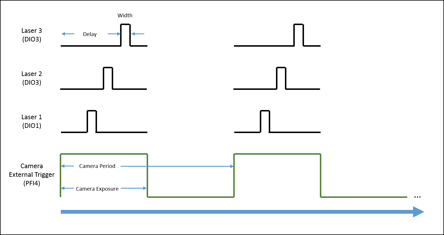
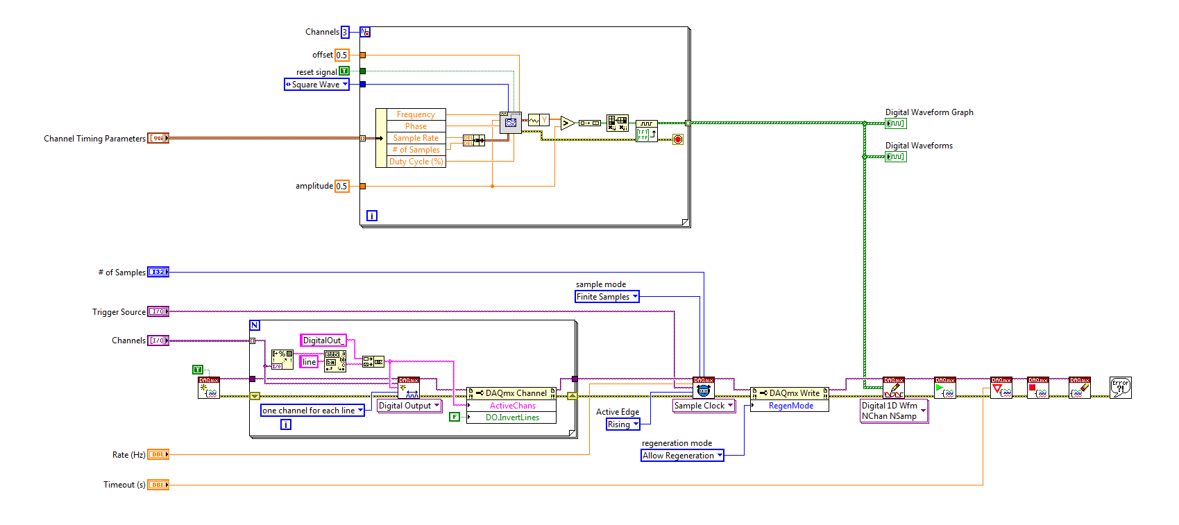
I'm trying to implement a system using a PCIe-6535 b connected to a high speed of SMB-2163 DIO. The system must be configured to work with a camera send a trigger (at the beginning of each show) to the PFI4 which in turn sends a single pulse on three digital output channels to lasers. Each output has its own specific deadline and the width. There is no counter on the SMB-2163, so I think I need to use Pulse Width Modulation (PWM). I saw this example and adapted to my system:
https://decibel.NI.com/content/docs/doc-8010
However, when the source to enter the DAQmx VI of sample clock is set to PFI4 (instead of the on-board clock) to receive input from the camera, changes in behaviour. The rate of sampling in the sample clock VI is ignored, and each element of the digital waveform is triggered. I need the sequence to complete each after trigger.
I am attaching a quick diagram of the sequence. Any suggestions on how I can get this kind of events triggered? (With the help of LabVIEW 2013)
Thank you
Mike
PLATES
The external signal must be configured as a trigger for digital startup rather than the sample clock. I do not think the 6535 redeclenchables supports digital output, so you don't have to restart the task after receipt of each trigger (something like this, however you can improve performance by committing to the task by using the task of control DAQmx before entering the loop).
Best regards
-
PCI-DIO-32HS error FFFCB820 (-215008)
DAQmx beginning gives this unknown error. What can it mean?
I'm under task of digital acquisition with burst (output clock) with an external device, data transmission. Alone, it works fine.
Then I need to measure the time after the end of playback (PFI6 = Dig0/ReadyForTransfer falling edge) to digital edge to PCI-6602...
If I configure (road/DIO/Dig0/ReadyForTransfer to RTSI2, installation on PCI-6602 counter measures), while DIO task is running (starting, measure, stop) both run fine.
But I need to sync.
If I first set up task HSDIO,
Then do road, set up and commit the task of counter configuration works very well.
But DIO-32HS beginning gives higher error.
Because of some course which is required for the DIO task, but is blocked by connection PCI6-RTSI2?
Solved.
Another development name of the channel to PFI6 instead of Dig0/ReadyForTransfer
or a DIO task commit before routing and configuration of another task.
But still don't know what to say error.
-
SBRIO DIO still available with 9693 mezzanine card?
Hello!
I intend to use a SBRIO (9626) and a map of mezzanine 9693 for plugging a 9853E module CAN.
However, I would also need interfacing #20 DIO, 4AI and 4AO. The signals will be be wired on J502 and J503 connectors.
Using 9693 mezzanine card, always will I be able to get/check status of DIOs/AIOs using the FPGA?
Hi zyl7,
The NOR sbRIO-9626 has only 4 asymmetrical on the J503 connector DIO lines as the sbRIO-9626 isn't a J502 connector. Using the 9693 OR prevents access to the CMR for anything other than the two C series connectors.
The J503 connector has 16 HAVE and AO 4 so that will work best for your needs that you can access IDC connectors and RMC connector at the same time in LabVIEW.
The isue with the sbRIO-9626 and the 9693 OR in your application, is that you will only access the DIO 4. If you need 20 DIO, you probably a DIO module in the second location of the 9693 OR add at least 16 DIO for your application. You can then use the 4 DIO embarked on the connector J503 IDC and the DIO on the C Series module to meet the needs of your application.
You could also add support on your daughter card circuits to multiplex your DIO 20 up to 4 lines DIO the sbRIO-9626 puts at your disposal. That depends entirely on the requirements of DIO, however.
-
entry of the FPGA 9402 trigger cRIO 9064 on DIO does not read
Hello
I have a cRIO 9064 using the Module C 9402 as a quick DIO in a SCTL. I use it in a (GPDD) digital delay pulse generator.
I've successfully the GPDD, triggered by a square wave generated internal, clocked at 1 MHz.
and I measure the pulse output perfect on an oscillascope.
My implementation is actually a clone of in: http://www.ni.com/example/31131/en/
However, when I try to trigger from an external 1 MHz, 6 Volt amplitude; duty_cycle 50%, square entering the DIO3 wave
There is no trigger, as seen on the Ticks_Between_Trig - which should be around 40, when it is correct release.
I used the method "Check status" to make sure that the 9402 is ready before the SCTL.
(Note: although it is labled Mod3 in the screenshot, it is actaully Mod1 and it simple namign incompatibility - which, once set doesn't change anything.)
I see not all digital HIGH when the input trigger control, what I do when you use the internal trigger.
The LED flashes, quite often even if actually at 1 MHz.
My question is what thing I must have the DIO 9402 read the input signal.
I followed the instructions here:
http://zone.NI.com/reference/en-XX/help/370984R-01/criodevicehelp/cRIO-9402/
but maybe I missed something.
Thank you
Michael
Resolved,
I had a bad input pulse generator which was flacky.
When I check the amplitude of the pulses on an oscilascope but a day later, when I corrected my code to include the ready method of Module C.
the amplitude of impulse was not working, but I've always tried to test with her.
Finally I double checked on the oscillascope again the trigger signal to find not suffecient.
Old eqiupment... then the warm-up does not.
Michael
-
Dear support,
I got my hands on some PCI DIO 96 maps in scraps of IBM tape libraries.
These cards were inside a special device PC running OS/2.
The card IBM partnumber is: 19 p 5156 (OEM 068-02369-0000)
Is there anyway that I can run these cards under Windows?
I suspect there is another 'firmware' inside the map, because it does not load the driver correctly.
Said driver Windows Manager: could not start the device.
I use NEITHER-DAQmx 9.0.2.
Some PCI card info:
PCI\VEN_1307 & DEV_0054 & SUBSYS_00541307 & REV_02\4 & 258F4AE7 & 4040
Thanks in advance.
H. Haken
Netherlands.
Hello h. Haken.
I did some searching on Google with the provider information you gave. There are a few other manufacturers who use the same name (PCI 96 DIO) for their cards. With the vendor information you gave, I came across the site of calculation of the measure .
In the end, we can conclude that this device is not working under the DAQmx driver. Please contact the manufacturer for the correct driver.
Best regards
Maybe you are looking for
-
Lenovo X 1 Yoga (20FQ) clean Windows 10 Pro Install UEFI
Hello I decided to do a clean install of Windows 10 Professional (x 64) on my Lenovo X 1 Yoga (20FQ). I'm currently pulling my hair out trying to install Windows 10 in UEFI mode, I want to do so that I can use all the features of the TPM and bitlocke
-
All In One C410b: HP C410b: Missing FAX printer
Hello just installed new Windows7, and tried to use the fax printer driver I was doing on Windows XP (HP Photosmart Prem C410 fax series). I can print the form of expexted and access the printer via http and it still works on my old PC. It is therefo
-
HP Pavilion 500 PC series 327 - ng: installation of Windows 7?
Hello I need your help I really am at the end of my know-how and really desperate. So I bought this PC today, I had nothing against Windows 8.1 in itself, but I wanted to use my internet and my (T-Online 6.0) software wouldn't work on Windows 8. So I
-
Hello I just got my new T420s, plug looks good, part number looks good, but it says T420si on the machine. Anyone know the distinction? Or it is just how they call low end models?
-
Our mobile sales are part of a domain but not connected to our network. Cached credentials are used to connect outside the office. Once they connect and view their desktops, they select the card from Verizon and use it to connect to our network via a