Documentation on a Labview VI
Hello
I'm doing some documentation/information on the VI I created. I created a VI that controls a bath of hot water by the use of a wave of fishing and watching the influx of Air mass flow controllers. I am about to leave my current job of laboratory (working in a University) and now have given the task of documenting the information available to me.
I'm wondering now 'exactly' how much should I document. The person who will end up using my code to continue and build off of it to automate some think more (lighting, pumps, etc.) will probably NO experience of labview. Then... I have attached my VI and I was wondering how I can be more helpful to a new user of Labview (it doesn't have to be perfect, I just need to get my message).
Questions/problems
1. I can't describe what is happening in section 3. in labview yellow notes...
2. I need to accomplish my task quickly... I'm leaving the country soon.
Your help is highly appreciated
Lydia
P. S.
I learned labview on mine and the schema is not the greatest. I believe that the next person will take a few parts and build off of it.
You want to make the person understand the logic of the program?
I mean, what function that task and etc?
I've used flowcharts of the to do. To illustrate, use blocks of LV to show what is happening in the world.
But your documentation is good, however. Just like the Bill, I don't have a background on what the application works, and I could understand it easily.
Nice work.
Tags: NI Software
Similar Questions
-
Hi all
Just bought a 2-channel digitizer high-speed USB-5133 and would pull in waveforms under LabVIEW 8.2. The instrument installed without event, works very well under NOR-SCOPE, is visible under the measurement and Automation explore (MAX version 4.5), passes all self-tests and test panels, but I have not been able to get LabView to talk about her. I'm new to LabVIEW 8.2, so I am probably doing something stupid. In general, I would use the DAQmx Wizard to create a simple analog VI. However, to do this requires that you use MAX to create a task DAQmx or Global virtual channel. Efforts to create such get as long as the dialog box to select a physical device and it lists no physical device available. No DAQmx handle seems to be able to navigate digitizer
I noticed that drop a dev1 IVI logical name dropdown list in the menu IS... Is this the road to get to this device?
Can anyone recommend a part of the documentation or example LabVIEW VI to speak directly to the USB-5133? We have need of a faster route to getting started he talks.
Thank you!!
You have an instrument of scope and which is not programmed with the DAQ Assistant or DAQmx driver. Yes, you can use the functions of class brought IVI to program or you can use the functions of NOR-Scope located on your Instrument with e/s > palette driver instruments. I do not have the NO-Scope driver installed on this pc, but I think that the example finder has some examples. Go to the hardware section of entrance and exit > Instrument Drivers
-
Flatten to a string to send arbitrary objects by messages from the user interface?
Hi people,
I am trying to send arbitrary data by messages from the user interface defined by the user to my labview interface. Something funny happens then: if I send the data through the message of ui, it seems I have something strange. There is only one character or nothing in the message of the user interface that reached my reminder.
It seems that flatten channel also creates control characters that are interpreted by NI TestStand and Labview not as members of the chain, and for this reason I only get incomplete data. within the action of testand, which creates the flattened data, I put a dialog box to display the string data, and it seems that at least up to 255 (ascii) characters are used.
Is there something like uuencode/uudecode to avoid this problem?
Thanks in advance
Okidoki, found.
His «binary"produced by «Flatten the string» string Apparently I thought, the LabVIEW data type is incompatible with the API of TestStand from LabVIEW. In conclusion I would classify this as a bug (sorry people, at least there should be documentation) API for LabVIEW TestStand 2014.
As a solution, I use flatten it in XML, which is a printable and human readable 'normal' string.
It was trial and error, and I'm not enjoying this.

-
WSN MAX, J-type thermocouple and serach time node issues
Hi dear all,
I use the WSN starter kit, I am able to work well on it, but have some problems and you smart guys do look in those.
1. once I installed 1.2 WSN software module poineer, I am unable to see Remote System tab in the tree of MAX, only my system tab is displayed. Even if I am able to see in my lvproject, to develop and use the application successfully.
2. the J type thermocouple which came once I set TC0 + and TC - of the WSN - 212 node according to documentations, then in Labview VI, I see in the temperature value 273.56 ambiguous as - values and change them to-244.67 as once that I touch at its end. My node is set by default to the range of temp type J and Celcius, click right property tab.
3 How long the knots will search gateway once its out of the range of gateway or I power off of the entry door? I experienced his seraches led for about 1 min then sleeps for 1 min at the start and then sleep time increases. I did this for 3-4 hours but after that 7-8 hours I couldn't see any LED flash for the search of the entry door. I needed to push button on the node, and then I start seraching.
Kindly help me on these issues. More will come once I have will probe deeper into the system.
Thank you & best regards
Zdzislaw qureshi
+ 923005178180
-
Carriage return line feed constant adds
I write a monotube ASCII file in Labview (32 bit 2011, SP1, Windows 7 machine) that will be read by a SBC embedded Linux.
I join my channel desired with a constant supply line. However, it does not seem to turn off 0x0A, I always get CR/LF (0x0D/0x0A).
I also tried a string constant in hexadecimal mode 0 "a." And with a string constant in '-display of Codes ", when I put '\A', it immediately turns into '\n'."
With all these options, the last two characters of the file that I build are always 0 a, 0 of a 0D not only as I need for Linux.
Someone at - it any idea, any suggestions? Thank you.
You use the function Write Text File? If so, it is by design and also documented in the LabVIEW help for this function, where it is said:
This function adds platform-dependent, the characters of end of line (EOL) to the elements of a table even if you right-click the function and remove the check mark next to the menu item Convert EOL .
The underlined part is my accent to highlight what can be a confusing statement. In the past, the help file says:
This function converts all characters from end of line to end of line, depending on the platform, unless you do a right-click function and remove the check mark next to the menu item Convert EOL characters.
It was stressed that this was not true with berries, as it ignored the checkmark if you feed in a table. So, the help file was changed to report. I still think that the help file is in need of a sentence previously to explain the general operation of the option convert EOL, with the sentence above, acting as a saving clause.
-
NEITHER 9233 Microphone conditioning of signals
Following an update of LabVIEW 2009 Pre - polarised FAT microphones work correctly with 9233 modules OR multifunction data acquisition. (They have been used regularly since 2007).
There is an important distortion of the signal calibrated showing the cutout of the positive part of the trace to higher levels of entry.
Connection from one system to the external packaging of signals MIC shows perfect sinusoid using the same (FAT 40AE) microphone capsule, (BOLD 26CF) amplifier, cable and NI 9233 - we have 2 examples of each element.
The only element that seems common to the fault is the conditioned signal of the NI 9233 following the update of LabVIEW 8.6 in 2009. I tried to change the level of excitement from 2mA to 4 and 8 with no benefit (specification of FAT said 4mA nominal 2-20 MA). I noticed that there are a few changes in the terminal configuration option dialog, but after trying to change this, it is the only viable option "nickname".
The determination of sources of external power and excitement for the microphone is not an option for practical reasons, but it does not restore the original function.
Is there a change documented 9233 with LabVIEW 2009 service or is there a simple solution to this change in behavior?
Thank you.
The interests of other users, it seems that the microphone needs a little more excitement to 114dB, where cut when it is used with the 9233 which can only provide 2mA. The installer works fine at 94dB, where 2mA is enough excitement. There are no errors appearing in the software, since it is a hardware limitation.
Kind regards
Michael S.
Technical sales engineer
NEITHER UK & Ireland -
Anyone have an example on pickering 40-575 matrix to define a model of close several relay?
Anyone have an example on pickering 40-575 matrix to define a model of close several relay?
I try to use a loop to set a relay at some point but he saw open relay closed when you set the relay in the table.
Thanks in advance.
Ah, see page 71 of the help file for this string of bad default. The documentation is pretty good
-
Hello
How can I save a sgl in grayscale as the Rainbow?
I analyze the image to grayscale, but for the presentation, I need to show it in the Rainbow.
my code does not work, however
This turns out be a "deep" enough question that penetrates in many subjects, not particularly well covered in the documentation of the IMAQ (or not always as accessible as one would like). There are several related subtopics:
- Display Images in grayscale on the screens of PC 'normal '.
- Efficient "colorization" to the image in grayscale.
- Use of Tables (LUT) in the Image colorization.
On several occasions, I've tinkered with elements of this problem, but never quite "understood." However, some comments and messages by Hatef Fouladi and some research around the Documentation of Vision LabVIEW has led me to a better understanding of this issue and a "partial" solution (I call that because he could not directly answer the question posed by the original poster).
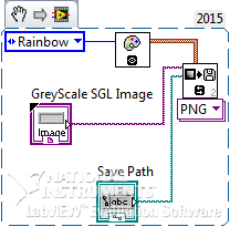
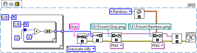
I will start your indulgence - as well for myself, my students and this Forum, I want to try to provide some of the 'missing Documents', which will need about a day or two of work. I can tell you that I have a provisional working routine that can take a 'gray gradient", and after applying the 'Rainbow' LUT, turn it into a PNG that... looks like a rainbow.
But the drafting of this response and is about to "apologize" to make you wait, I realized that I had, indeed, 'colorized' my Image (as verified by the on-screen display), I had forgotten that the goal was to save the PNG image colorized. Then I added the function Write PNG, saw the entrance of the "color scheme" and said: "Hmm, I wonder...". ", which brings me to this:
I chose to work with Images in grayscale U8. A note of hard to find here, from the manual of Vision LabVIEW 2010, explains that the PC screens can show 256 gray levels, so U16 Images must be 'remapped' to a range of U8 before visualization in grayscale.
The nested for loops generate a 128-by-128 pixels "grayscale, with 0 (black) in the upper left and 254 (white, almost) lower right." This is the Image I want to use, write it as Gray.png. The IMAQ write file 2 (IMAQ functions changed a few years ago, many taking a suffix '2') has a Color Palette and IMAQ entry provides some standard LUTs (that he calls "Pallets"), including "Rainbow", using IMAQ GetPalette. I plugged this place to a second function write file 2, and the results are presented below.
I still intend to write this to the top again, but this "solution" is so simple, and explain what I hope is already sufficiently complex, I can take a little more time to "do things." I'll (eventually) post here (or, at least, these are my good Intentions).
Bob Schor
-
Hi, actually I want to save as a PDF labview code to prepare my documentation, it is possible to save in pdf Formate? Please answer me quickly...
Thans in advance.
When you print a VI, you can choose to print documents of the VI and print it to the printer. If you install the PDF printer, it will appear as a selection. PDF Creator is one of the PDF printer free that you could use.
-
Using the acquisition card in Labview
I am considering the purchase of an NI PCIe-8242 acquisition card to go with my camera ace acA1300-200uc of Basler. I can't find any documentation on how to actually use the inside of a frame grabber Labview, and I'm very inexperienced with regard to the use of Labview. Anyone has any advice or tips on how I can use the acquisition card?
For reference, I need start a video stream given a trigger to an different Labview vi, then take some pictures and save them to a directory on the computer in the first 30 seconds. I need to keep the video stream up to the end of the trial. But I can't save any video - only a few pictures.
Thanks in advance!
Although he needed the VDM, why would you recommend the duration? He couldn't really use it. It would be wasted money. The only value to it is if you already have an application built using the VDM development software. (which is more than one Service that is more than the card it looks)
If you have no customer Service, certainly grab some cheap acquisition cards. If you already have GOING, I would skip the tips here to blindly buy the card and test your USB3 ports prior to the purchase of surplus material.
As far as how you would work with the BT acquisition card? Really, you won't. You will work with the camera that you plug in LV you won't see anywhere mentioned acquisition card. In MAX, it'll be the camera. In LV, you will use the resource name of MAX. The acquisition card will just be additional USB3 ports.
-
Ethernet I / P Communication between Fanuc LR Mate 200iC and LabVIEW
How can I read the outputs and write entries of a device, Ethernet/IP, using the NI Ethernet/IP drivers?
I recently get the NI Ethernet/IP driver OR to communicate with a robot of 200iC Fanuc LR Mate using this communication protocol. In fact, I set up the robot as a parameter to map digital 1 to 64 and output digital from 1 to 64 and through the Ethernet/IP configuration.
What I do is for example, a specific moment in my logic to the status of an output of the Fanuc Robot to take measures, or give some input to the Fanuc Robot so do some operations. Now, as I noted above, I get this drivers recently and apparently they are new or regular technical support do not support for this product. Basically there is no apartment of the LabVIEW help on this driver documentation, and this help doesn't help too much.
So, if someone can help me to make this work I really appreciate it a lot. I'm in the middle of a project we showld integrate via Ethernet/IP. Here is a screenshot of the the inputs and outputs in the configuration of Fanuc Robot are on Slot 1. Attached is a table with a summary of the Fanuc Robot of the configuration settings that should be used to set up the scanner (in this case, LabVIEW):
I'm using LabVIEW 2011 with Ethernet/IP v1.2 drivers on a Windows 7 Professional
Once again, any help on this will be really appreciated. Thank you.
Hi Ferdinand,.
Please refer to the help as documentation below:
1. open LabVIEW, go to the Help Menu-> NOR-Industrial Communications for Ethernet/IP. This is documentation of EIP support for all applications.
2. in him getting started window of LabVIEW, please go to find examples. And check the directory:
Input and output hardware-> NOR-Industrial Communications-> EtherNet/IP
In this directory, there are several examples of use of the PPC.
And for your case, read the example in ".vi AccessAssablyInstanceData (Explicit)", which should be very similar.
For any question below, please do not hesitate to contact me.
Thank you.
Chris
-
Get the 1097 error when trying to call a Labview DLL
I had to write a wrapper DLL to use some functions in the DLL to a third party, and I'm having a few problems. I created an executable to test my code and it works fine, but when I try to execute the same function in the DLL that I created in Labview, I get error 1097. I read through most of the posts on this forum about this issue, but none of the proposed solutions are working for me. I'm sure this isn't a question of transfer settings to COLD LAKE because I changed the function so it only accepts a single entry (a number he obtains from a Subvi, which came from the third-party DLL, this entry is working with a bunch of other functions, so I don't think that is the question).
I have attached the C code that creates the wrapper, but I don't know how it is useful without familiarity with the functions of the original DLL. I hope that someone can spot something basic I am out of my code, but please let me know if I need to call something else.
I use a Labview 32 bit version 2012 on a 64-bit Windows 7 computer.
Thanks in advance for any help!
You should read the documentation on LoadLibrary() and understand. Essentially if you provide a full path to LoadLibrary() the DLL MUST be present at this place so that LoadLibrary() will succeed. If you pass only the name Windows DLL will ONLY search in these places:
(1) if the module (the DLL) is already loaded it will return a handle to the loaded module and increment its reference count
(2) if the referencing module contains a manifest (either incorporated into the image module or in a separate manifest file in the same directory as the executablemodule) specyfying a version number for this DLL will load this DLL with this version of the SxS (side by side) location and failure if it is not present
(3) if the executable load contains a manifest (either incorporated in the executable file or in a separate manifest file in the same directory as the executable file) number specyfying a version for this DLL, it will load this DLL with this version of the location of SxS (side by side) and fail if it is not present
(4) it will search for the DLL in the same directory as the directory where the current image of the process is loaded. It is NOT the directory of the DLL loading the DLL, BUT the directory where the EXE file from which the process was created.
(5) in the system directory
(6) in the Windows directory
(7) any directory in the PATH environment variable
(8) the path of current directory which is a location managed by windows by process and changed the two explicitedly when the application calls the API SetCurrentDirectory() but also implicitedly by things like the file selection dialog whenever it is rejected by other means than the undo operation.
Essentially putting your dependend DLL in the same directory as the wrapper DLL does NOT work when you use the name of the DLL only UNLESS you place the two DLLs in the same directory as your executable file. If you don't want this restriction and want to be able to move these modules together in different directories, you don't have to create the correct path in your wrapper to LoadLibrary(). Basically, you must have the code to determine the location of your DLL wrapper path and then strip her own name and add the DLL name wrapped in it and then move to the LoadLibrary().
There are several ways to determine the path of the current module. The simplest if you don't mind having the name hard-coded in your code DLL would be to ask GetModuleFileName (GetModuleHandle ("yourDLLname"), buffer, size).
-
Hello
Now I'm trying 2 cameras andorid in labview using the IP camera adapter installed in the PC interface.
I managed to interfacing with a camera in labview, it worked!
the problem is that I couldn't find a way to put 2 IP addresses of both andorid cameras I have!
Y at - it deals with any other software that leaves me more than one IP to the interface? or how to manage the software at the interface of two cameras (2 IPs)?
Thank you very much.
Now, I think I understand what you are doing. You have followed the instructions on this Web page: http://digital.ni.com/public.nsf/allkb/3D9CEA3E7B26FA4586257A56004E4507?OpenDocument
The problem you encounter, it's that the IP camera adapter supports only a single IP address at a time. I don't know what this software does exactly and there seems to be anything in the documentation that explains how to make more than one camera at a time.
Also, I'm sorry I wasn't very clear in my instructions. You must create the INI file to the specified location. It is enough to create a text file and include the text I mentioned. Save it as IPCameras.ini. Now, see if the camera stands as an option to the MAX and LabVIEW.
Jeremy P.
-
LabVIEW HSDIO active channels equivalent property in c#
Y at - it an equavalent c# of active channels LabVIEW HSDIO set/get property. I looked into the latest version of the HSDIO c# wrapper and I couldn't find the enum property nor the constant property for use with the method SetString().
raffythegreat wrote:
Y at - it an equavalent c# of active channels LabVIEW HSDIO set/get property. I looked into the latest version of the HSDIO c# wrapper and I couldn't find the enum property nor the constant property for use with the method SetString().
You'll have better luck asking in the forum hardware DIO.
I took the last envelope http://www.ni.com/product-documentation/52900/en/ and he did not see the method you are looking for.
-
To access the properties of a file of sequence of labview
I want to produce a report based on data from file in sequence to relieve my documentation of software needs that must be in a specific format that. To do this, I want to write a labview program and enter the parameters of information of various teststand sequence and put them in a specific format.
Most of the labview for testatnd tools require a context of sequence to exploit. Is there a way to do this without having to open the entire teststand application and add a specific sequence?
It seems to work for me. Let me know if you have any questions.


Maybe you are looking for
-
Whenever I try to use Firefox interupts message saying that qwikster says that I need to update my media player immediately. I don't have a media player. Help me get rid of this message.
-
QuickTime error when installing Windows 10
Well, I'm currently on my Mac Pro (2014) right now and I use VMware Fusion to install Windows 10, but when I install QuickTime 7, he started to say this error: "ul_catalog.98cb24ad_52fb_db5f_ff1f_c8b3b9a1e18e not found in the quicktime.cab CAB file.
-
cellular data should be on all the time?
cell data in parameters should be on all the time?
-
New installation of Windows 7?
Good, everyone. For the past little while, I was in need to wipe and reinstall my Windows 7 after tons of viruses and crud that makes my computer unusable. I deleted the partition Windows 7 original, as well as all the documen ts, files, etc., not to
-
Hello I have Windows server 2003 I have the server license terminal server, but one of my XP machine, which I'm calling his error remote desktop by giving as belowThe remote session was disconnected because the local computer client access license co