Draw a myDAQ signal power spectral density.
Hello
I need to draw the power of a signal acquired using myDAQ spectrum. I have already acquire and track the input signal. The example given in Labview for the power spectrum using a predefined sine wave and replacement of the sine of the input signal does not work...
Help, please...
Thank you
bns2804 wrote:
This part has worked well for me as well. But the problem I was getting was that the graph for the power spectrum was limited to 500 Hz only, despite the change in the range of the axis...
Thanks a lot for help
This is because you are sampling at 1 kHz (1000 Hz). Remeber Nyquist (you must taste a signal at least twice its bandwidth)? If your FFD don't go up to 1/2 of the sampling frequency.
Tags: NI Software
Similar Questions
-
The power spectral density function counts inaccurate amplitude caused by the window function?
I'm new to this forum, so please let me know if this would correspond better to a different discussion forum.
Here's the question:
I would like to know if the power spectral density function ("FFT PSD for 1 Channel.vi") automatically compensates for the loss of the amplitude of entry caused by the window function. In other words, is a specific window correction factor applied within the PSD vi or do I apply manually?
Details of the background:
I tried to answer the question myself by generating a sine wave sampling, it as it is periodic in record time (i.e. 0 to each end of recording time). The frequency of the sine wave was such that the frequency would exactly correspond to a spectral line in the PSD. Then I generated the PSD of the sine wave twice: once using a Hanning window and once using a rectangular window (not on average in both cases). The rectangular extent of the PSD with windows to the frequency of the sine wave is 1.5 times the size of the PSD with a Hanning window applied.
The experience above indicated to me that a manual setting of the PSD output for the function of window was necessary, however, I repeated the above experiment using random vibration data and does not clear 1.5 x factor. I have also been informed by his colleagues that the PSD should set for the window function.
Thank you for your comments.
Spectral leakage. When you use a finished sample data from the spectrum resulting is the convolution of the spectrum of the signal as if it extended indefinitely in time with the spectrum of the window. Even if you do not use a window function, you actually have a rectangular window the same width as the sample size.
Draw out of the VI PSD with all style of trace to show points to the data points. Turn off Auto scale on the X axis, and expand the graph around your pic. Look at the results of different windows. In any case, there are several values non-null. With actual sampled data of limited duration, you will never get the idealized line spectrum.
If summarize you the output spectral value remains close to 3.2 for all windows.
Lynn
-
Amplitude of power spectral density is about 1e6 times higher than it should be
Hello
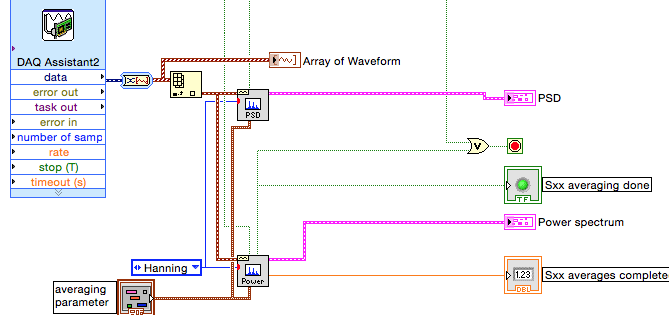
I use vi of power spectral density (PSD) and power spectrum vi in the process the same time acquired by data acquisition (attached figure) signal. I sent in a 0.1V sinusoidal signal of 1 kHz in data acquisition, and the power spectrum gives me the right power RMS at 1 kHz (which is 0.05), but DSP vi gives me 1670, which isn't fair. The amplitude THAT PSD gives me must be smaller that the power of amplitude spectrum gives me. This is supposed to be a simple treatment, but it drives me crazy. Is someone can you please help me solve this problem?
Thank you very much.
INSA
If you convert the dynamic data Type (badly) from the DAQ Assistant for an array of waveforms, sampling rate information must be included and none of your additional calculations is required because power Sprctrum and the PSD VIs will take care of this... This is what Dennis mentioned in his post.
We cannot do a lot without data. Please display waveform data type and add a waveform table indicator. Run the VI until the indicator data. Stop the VI. On the Edit menu, select use current default values. Save that VI, possible with a different name and post it. We will then have access to your data.
Lynn
-
E4200 v2 wireless signal power is intermittent
Just updated firmware for 2.1.39.144146
have 5 GHz mode - mixed, WPA2, 40 mhz, channel 161 channel width
the rule 2.4 GHz mode - mixed, WPA2, 20 mhz, Channel 6 channel width
Online technical support said it could solve my problem, but my old e1000 had a stronger and more coherent (fluctuating) broadcast signal.
My PC and the router are in the family room at the back of the House. The signal strength is Ok in the first room, but 2nd room in front of the House (30 feet and two walls away) it is 3 bars to nothing all the time. We have a guest who stay with us two days a week. There has never been a problem with the signal strength of the e1000 for recent years, but the v2 e4200 behaves like a piece of * beep *. I spent over 60 minutes with an online support person whose answer was to upgrade the firmware (which of course now removes a direct access to the router via the browser.)
I hope that someone knows what I need to do to make this work, or it goes back to Amazon and I'll buy another brand of dual band N router.
Change the channel of your router to 1, 9 or 11 to optimize your wireless signal. Maybe this link can help http://www.howtogeek.com/howto/21132/change-your-wi-fi-router-channel-to-optimize-your-wireless-sign.... If still the same, I think this device needs to be replace.
-
Why not Apple TV remote control IR signal power?
ALMOST everything MY Gen 4 Apple TV can do. He turns on the TV and can control the volume of my audio receiver via IR
Then why the hell can we use the same IR function to activate the receiver as on and off so?
Looks like a fairly simple function that would be pretty easy to impliment through IR control sampling as is the volume control. And then just implement that Protocol in the sleep unit as is the HDMI control.
Oh & the Remote App should really be able to send a command to sleep for Apple TV
The pieces are there, but not quite put together :-/
This is a user forum, you're not address Apple here.
Provide feedback
-
I'm using strain gage accelerometers to collect data from acceleration axis X, Y and Z on channels separated as a way to quantify the vibrations in the cabin of an off-road vehicle. Using the DASYLab "formula module" I put across the output of the accelerometers to read directly in gs, or 32 ft/s/s = 1 g.
If I use the DASYLab 'fft module' to provide a spectrum of power for a waveform g time density vs generated by one of my accelerometers, what are the scale units which are delivered by the "Y/t diagram module? I know that the x in the table scale units are Hz.
I am producing a figure of displaying data that has the same format as power spectral density data presented in the figures in Mil - Std - 810 G method 514,6 Annex C. This paper presents data from sprectral in the form of curves of (g ^ 2) frequency vs /Hz.
So far, none of the data I gathered in my vehicle, looks something like the data presented in the in the mil specs.
Thank you for reading the question, I asked, given it and answer this question instead of going some other marginally related topic. I sincerely appreciate your knowledge and your willingness to share.
-
Why Express PSD gives a different result of amplitude as FFT PSD?
Hello
When I use the express VI of spectral measures to trace the power spectral density, I get a different result than when using the FFT PSD VI. The data are the same but the amplitudes are different in the PSD plot. Everyone comes through this?
Thank you
Donners,
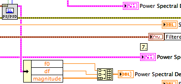
The PSD2 and graphic PSD2 are different because you are breastfeeding two extra points in the tables (t0, df). When graphic entry of data in the tables, they interpret not automatically information of t0 and df. Actually they do not yet receive this information. You must program the scales with nodes of property. If you simply draw the order of magnitude, the spectra are very similar.
^ ^ ^ This confuses only the chart!
The spectral forms differ slightly as the power spectrum of FFT and PSD.vi uses a default Hanning window.
Lynn
-
Frequency domain scaling graphic of waveform
Hello world
-I m buying a random voltage signal using a sampling rate of 200 kech. / s on my device NOR and trace the signal acquired on a waveform graph (Figure 1-a). After tasting the random voltage signal my Labview VI also calculates the PSD (power spectral density) of the random signal acquired and it is plotted on a waveform graph (Figure 1B). As the sampling frequency used was set at 200 kech. / s, the maximum value on the x-axis of the curve of PSD´s waveform should be 100 kHz (Shannon´s theorem). When Labview trace PSD´s waveform graph, the maximum value appears as 1. Is it possible to scale the chart of PSD´s waveform in order to define the maximum value on the x-axis as 100 kHz?
Thank you in advance,
Best regards!
Of course, your numbers of the scale correctly and use a property of the range axis node x (your pdf says absolutely nothing about your program or your problem with it. Code would at least tell us something.)
Cameron
-
1 reading coulumn .csv file and display its PSD
Hello
I have a .csv file that corresponds to the readings (all the 1 second) voltage.
I am able to read using LabView, I use Read spreadsheet take his exit (all lines) and then select the first column only, pass it to build a wave form and then, view the power spectral density.
Unfortunately, nothing is displayed.
Any ideas? The file only contains double numbers (for example 0.01234 etc.). There are 50 thousand lines.
Thanks in advance.
Hello
I solved the problem in unbundeling the signal out of the PSD, then take the subsignal of greatness and him alone, then wads of scale together.
-
What is the best way to generate the density curve for example spectral dBuV / 200 Hz?
There are large screws for PSD, but this is an easy way to create a field of spectral density with units dBuV/200 Hz?
Hey steveMAX,
If you have equipment that can acquire these tensions, then it should be too difficult. You can use the Express VI spectral measures to produce the data. This will automatically give you the output in dB. You can then resize the axis on the graphical indicator you create so that you can display the correct data and label the axis correctly.
Kind regards
Chris
-
determine the angle of a complex signal phase
How can we determine/measure the amplitude and phase angle, separately, signal output complex in AWR in circuit level (schematic) design?
It depends on what you mean by complex 'signal': power, voltage or current? If it is a simulation of harmonic balance, you can use measures Pcomp, Vcomp and Icomp for value complex to a specific harmonic and choose 'Mag', 'Angle' (or "AngleU") as the modifier "complex" for the measure. This can be traced and then compared to what you are scanning. e.g. power, frequency, etc. If this does not answer your question, attach a copy of your project, or at least a photo; So we have some background.
-
generation of clock using mydaq
Hello world!
I just have a very BASIC question. I know that some of you may find it easy.
Again, I'm new in LabVIEW and I try to use a data acquisition equipment NOR myDAQ. In the application, that I'm doing, I need to get a pulse generating myDAQ signal and use it as input in my multiplexer. I searched for positions and I think that none were asking such a simple question.
If there is no solution for this, please link with me. Thank you very much!
Kind regards
Falsehope
FalseHope wrote:
I am afraid that I can not do. I'm only using the computer lab of the school and he removed the LabVIEW examples folder (perhaps to prevent students to access the examples during the reviews of practices). So yes... I am a student with limited access to LabVIEW.
But I talked to the it DEPARTMENT of our school and it allowed me to download the examples instead. However, I can't find the codes available.
Kind regards
Falsehope
IMHO, he is a stupid thing, a good teacher can create easily of exercises and tasks of review to "measure" the real knowledge of the students, even if they use the built-in LabVIEW examples. A school should help during the learning curve and not by disabling the examples incorporated, but giving creative tasks...
I've attached an example VI that will generate an output of 1 kHz by DIO-3 and DGND counter. (I tested with a myDAQ device, it works)
-
V570 No. reactivation, no video and now... no power
I have a V570 which is about a month or maybe a little less. He ran no sweat all yesterday. I have either in the night after checking my e-mail one last time and I thought it would just go to sleep normally as he does, but I can't really confirm he did as I also went to sleep.
This morning, I came and tried to wake up and nothing happened. Power button when he saw was turned on as well as some of the other standard lights... but not video, no fans to come on, nothing. So I thought that maybe it has crashed or locked up. I held the power button and it shuts. I waited about 30 seconds and pulled it back. He whirred to life, but still no video. So I waited... and waited... and still nothing. Yet once, I stopped him holding in the power button.
Disconnected everything of it (USB wireless KB and mouse, on an external monitor USB Wacom drawing tablet) including the power cord. Knocked down, it exceeds, jumped battery, everything went well, put the battery in place. He nosed over and press the power button and nothing. LEDS were not even light upward this time. So, I thought that maybe the battery is a dead unit... I plugged it back in and still nothing. No LED, no fans, no nothing. Jumped battery out and plugged in the power and the LED flash, but all that happens when I hit the power button what I guess is that the CPU fan turns at full speed. I don't know if this laptop can be run without the battery installed when the power supply is plugged... My old HP, which has allowed so I thought it was worth the try.
I'm waiting as I type this with support from Lenovo, but I thought I'd branch out and see if someone else here knows this or has a solution. I use this trick to work, he's been solid for the moment I got it but * beep * it's going to make my week suck if I can't he get up and running.
Edit - I forgot to mention, I tried the onekey recovery key when it was turned off and no result in doing so.
-
Save the wave shape of power spectrum
Hey labview masters, I need help! I'm developing a labview program to calculate the power of a waveform spectrum injected into a signal acquisition interface 4461. The program gets the fft of the captured signal and return the array of power, as well as background noise spectrum. He is then sent to the host via a TCP connection.
Everything works fine except that I can't record the signal power spectrum more he sent to the host. I tried to trace all the x / y values via the command waveform.vi in the field, except that I can't add the axis labels.
Can you tell me how to trace the full spectrum of power, add labels and save it in the pc?
Thank you guys
João Matos
Export image is an Invoke node, not a property node.
Right-click on the graphic terminal of waveform and select Create > invoke node > export Image.
Lynn
-
Hello
I am using Labview 10 and wants to apply the Maximum power transfer theorem. I have attached a VI that allows to calculate the maximum power. Now, I want a way in which I can draw the graph of power v/s Rload/adapted.
The attachment method does not work. Please help me on the sameJay
Jay,
Your other posts, I think you need to do two things:
1. ask about LV these types of programs simple loop are very basic. If you do not understand this kind of thing, you have no chance of reaching your goals.
2. you define exactly what you want to do your exercises in the laboratory. They are to be purely software simulations or will you need real voltages, currents, temperatures and so forth, to measure? If it is to be all software, then you must select all and set all equations and algorithms for these models. If you're going to make measurements of the actual physical quantities, then you need to define what you will be measuring and the range of allowed values for each parameter.
Once you have these definitions, then you can start to design your system. Select the measurement equipment. Select software architectures. Structures of program design. Adapt the algorithms, if necessary, of the LV data flow model. Then start writing screws
Here's a simple VI in a loop for the calculation of your diet. Note that your model is not the same as a photocell so the curve is different.
Also note that most volunteers are the people on this Forum. We are happy to help you learn to use LV, but we will not do your work for you and we ask you to make a reasonable effort to do your part.
Lynn
Maybe you are looking for
-
time machine the ignored files
One of my Time Machine backup disks is not back up all files on the drive that I copy. Ignored files are for the most part, the Photoshop files. Everything worked very well so far.
-
Whenever I try to use any menu in Firefox, they sparkle inside and out. It is extremely difficult select Favorites or even Alt click on a link to "Open in New Tab" I have hover over menu items, they disappear and then come as soon as I move my mouse
-
Hi here is the id but I can't find anything on this driver is needed thanks in advance to all PCI\VEN_14F1 & DEV_1024 & SUBSYS_1006144F & REV_08PCI\VEN_14F1 & DEV_1024 & SUBSYS_1006144FPCI\VEN_14F1 & DEV_1024 & CC_178000PCI\VEN_14F1 & DEV_1024 & CC_1
-
which Windows programs can be removed safely if I can get more space on my hard drive?
I have an Acer Netbook - installed Windows XP Home Edition, SP3, 98 GB RAM, 1.60 GHz. I continue to have problems with the lack of disk space. I already deleted all the photos, photos, etc. I bought an external hard drive with 1 Terrabyte to use (I h
-
How can I view programs with a picture of a padlock on the subject
some how (I didn't for her) some of my programs have an image of a (locked) padlock on this subject. How to unlock? I have a laptop dell studio 1749. Thank you. Bill.