Frequency domain scaling graphic of waveform
Hello world
-I m buying a random voltage signal using a sampling rate of 200 kech. / s on my device NOR and trace the signal acquired on a waveform graph (Figure 1-a). After tasting the random voltage signal my Labview VI also calculates the PSD (power spectral density) of the random signal acquired and it is plotted on a waveform graph (Figure 1B). As the sampling frequency used was set at 200 kech. / s, the maximum value on the x-axis of the curve of PSD´s waveform should be 100 kHz (Shannon´s theorem). When Labview trace PSD´s waveform graph, the maximum value appears as 1. Is it possible to scale the chart of PSD´s waveform in order to define the maximum value on the x-axis as 100 kHz?
Thank you in advance,
Best regards!
Of course, your numbers of the scale correctly and use a property of the range axis node x (your pdf says absolutely nothing about your program or your problem with it. Code would at least tell us something.)
Cameron
Tags: NI Software
Similar Questions
-
Acceleration in the frequency domain
Hello
I enclose a vi that I already modified the existing example. I will use this vi to measure pressures (pressure sensor) and acceleration (from an IEPE accelerometer). Each of the two sensors is connected to a housed in a chassis CompactDAQ C Series module connector 4. The pressure sensor measures the pressure of the water flowing in a pipe while the accelerometer will simultaneously measure the vibration of this pipeline caused by the fluctuation of water pressure. In this vi, I am connecting a signal of pressure and acceleration TDMS file and then read the two signals on the cards of distinct waveform. The acceleration signal is written and read in the time domain. I need your help to make change more on this vi to take the acceleration signal and read on a separate table in the field frequency and written also the frequency of the field values in a file of PDM. After this change, the vi is supposed to have three graphics of waveform (pressure, acceleration time-domain and acceleration in the frequency domain and opens two tdms files, one for pressure and acceleration in the time domain and one for acceleration in frequency domain.)
I tried many ways all failed because I'm not very familiar with the measurements of vibrations.
I thank in advance.
Hello
It is important that you should decide if the frequency data you are interested in are constants based on time, or if you need to know how the data of frequency changes over time.
For constant frequency over time, take a look at the Fast Fourier Transform: http://www.ni.com/white-paper/4541/en/
If you need to know how the frequency display, take a look at the analysis of the frequency of the common time: http://www.ni.com/white-paper/3548/en/
-
Filter of time domain frequency domain filter
Hello
I am applying the weighting filtering of an audio signal.
I'm to draw the response of the filter in the frequency domain.
How can I turn this into a time domain filter and use it with a real audio signal?
In theory, it's pretty simple. You take the s-domain transfer function and apply the bilinear transform. After a few edits, you can extract the coefficients 'food for animals-descendant' as well as the coefficients "feed-forward". These coefficients can serve as input of the filter of Labview functions. As I said, the theory is simple, but I think it will be a tough job to do this. Weighting is used in the measurements of the sound level, to mimic the curve of the human ear. If you plan to use spectral analysis in your application, you can skip the filter and apply your formula for your spectrum frequency bins. In this way, you can save a lot of work, because you stay all the time in the frequency domain.
-
Hello world
I'm sorry if the question may seem stupid, but how can I draw the sinusoidal frequencies on the x-axis and the corresponding amplitude on the y-axis after that I could achieve fourier transformation?
Thank you very much in advance for any advice.
Andrea
Use a graph of a waveform.
I'm assuming that your FFT gave you a data table, a F0 and a dF.
-
Frequency min & Max of a waveform in BT 7.1
I'm modifying an old program written in LV 7.1
Over a period of 2 seconds, the waveform sinusoidal 60 Hz nominal skids to approximately 63 Hz and corrects. So while 2 seconds, the frequency is in flux, change until he moved back to 60 Hz. It's the old style waveform data - just a table of single precision.
What is the best way to determine the frequency of peak during this period?
Thank you
lmd2
-
I have included my code as version 8.5 for those who have not yet upgraded to 8.6. I have also included some screenshots so that you can replicate the results I got. I hope that some signal processing guru can shed light on what I mention it further.
This VI convolves the signal of impulse response of a simulated servomotor which is essentially a damped sine the input pulse which is a step function. The signal resulting convolved should be IDENTICAL to that of the step response of the engine which is RED on the display 1. As you can see the convolution that results in table 2 shows the same structure of frequency, but its magnitude is INCORRECT. As you can see in the catches of 2 screen sizes differ by a factor of 2 & done the sampling frequency of the wave. Why the sampling frequency, impact on the scale is also very strange & disturbing.
Would appreciate any corrections & explanations so that I trust the convolution of the other wave forms of entry than just the step function.
OK, I think I have it working now. Your premise on the effect of sampling on the derivative is not the issue. Does it affect what the FREQ of levy is the basis of time of convolution. As the convolution product is not continuous but discrete the length of the array should be taken into account & the sampling frequency must be consistent with this length of array as well as 1 second corresponds to 1 second. If sampling freq is 2 kHz & the length of the array is 1000 then to get the correct time base by a factor of 2 must be taken into account. In addition, to take account of the DC, shift of the ZERO gain factor must be added to the convolved signal to get the correct size.
Thanks for making me think more deeply.
-
How to detect the peak frequencies in the frequency domain?
Hello
I built a small test consisting of two sine waves of varying frequencies, program it is and subsequently FFT is performed on it to find the frequencies of two peaks. I tried to display the values of these two frequencies somehow, but I can't find a way.
I searched the forum before asking the question, many of them suggested using extract more Information VI tone I tried and could not get any results.
I have attached to my account. Please take a look. If you know all the discussions on the forum directly related to my problem, please just cite it.
Thank you
LD
Don't wire the tone of several extracts the wire coming from the Express VI of Sprectral. You need to run on the thread after that the two signals are summed.
-
How ro provide Convolution in the frequency domain
Hello world
I have a problem with application a convolution of the image and kernel smoothing in LabView. The idea behind this is that convolution is a multiplication by the area of the Fourier transform. So firstly I want to apply convolution by standart IMAQ convoluted VI, then, to do essentially the same thing, but do it manually FFT of the image and the kernel and then their multiplication by then apply inverse fourier transform and observe the resulting image. Finally, I get two different results, but they should be the same, I can't get the idea why.
-
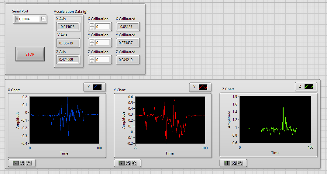
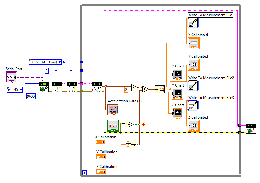
Get the frequency of a graph in real time of the waveform trace
Hello
I want to get the frequency of the graphics path in real time. The data comes from a connected to an Arduino UNO ADXL345. I use LINX to read data.
I separated given x, y, z in order to plot separately and later to get their respective frequencies as well.
Here is an excerpt of my VI as well as the front panel.
I used a the Measurment file for each axes entry so I have a copy of the data.
Before posting, I tried the LabView Spectral tutorial first. But it's different from what I want to happen because you know the exact frequency in this tutorial.
I have also attached my VI.
Thank you!

If all you want is to know the spectral content of a signal in the time domain, there are a number of examples show how to do it. I would start by looking at the functions of the FFT.
Mike...
-
I would like to turn my non-stationary ground penetration radar and the seismic signals from the time domain to the frequency-wave number domain in my LabVIEW 7.1. The goal is that later f-k/Stolt migration. But I have found no useful VI in LabVIEW. Y at - it all?
Thank you.
Wallace
Greetings Wallace.
Unfortunately, to my knowledge there is no integrated inherent method of LabVIEW to perform this operation. While we have another screw for the conversion of area, such as the field of simple time in the frequency domain, etc., this seems to be outside the scope of what the development system and tool boxes offer at present. If you think it would be a good feature to include in LabVIEW, please feel free to create a product suggestion to www.ni.com/ideas.
Kind regards
Michael G
-
help understand the digital and graphical waveforms
Can someone explain to me how digital waveform working with NOR?
I did a channel physical and wired to a DAQMx create channel then I have it connected to a NSamp of 1Chan ereading Wfm DAQMx and then wired it to a graph of digital waveforms.
I put digital and graphical digital waveform playback in a loop.
When I run it, it seems to me only to get 1 sample on the graph per loop iteration.
The desired output is to add each digital sample as a function of delay which can connected and or scrolls in time to examine what is happening with the signals.
Where is my mistake?
My VI is attached.
Any help would be greatly appreciated!
Also another quick question, is there a 'comment' as a command / / c or ' in VB? Thank you.
Hi Henry,.
Thanks for the post! It seems that you are having problems with the acquisition and the graphic representation of digital data using DAQmx and LabVIEW. You are right that the type of program you have returned a single sample every loop iteration, because you make an acquisition without buffer, timed by the software. This means that the program reads a sample for each channel, whenever the DAQmx reading VI is called, which will depend on the speed of the software will run. In addition, when you view this data, the chart will only display data acquired for this iteration of the loop (that is, in this case, a single sample).
To accomplish what you want will take some extra work and overhead costs in the software, but you can essentially use a shift register and accumulate samples that your program runs. There is a practice done just VI to do this kind of thing with digital signals and is called DWDT Append Digital Signals.vi (this can be found in the palette of functions in respect of programming"Wfm Digital Waveform"). I created a small example which you should be able to run that does this. What actually happens is that the waveform is rewritten each time with new data added in addition to the data passed in. To be able to scroll back and view this data, I turned off automatic scale on the x axis (if it is enabled, it will constantly increase and tries to show all the data at the same time) and selected just a data window to display. In addition, I added a horizontal scroll bar to scroll through the review data.
And to answer your question about the code comments in LabVIEW, this can be done with a clear Structure of the diagram. You will find this structure in your palette of functions in respect of programming' Structures. Using this structure, you can select a part of your block diagram to disable and switch to the active state of wire through the or add different features that will run. Hope this helps and good luck!
-
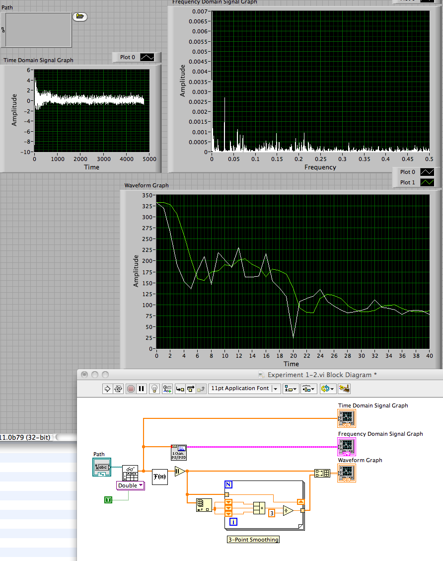
How to reduce the noise/smooth and frequency diagram
Hello! I have a text file that contains a signal. I had read in a format of waveforms and trace the signal in the time domain. I then put the waveform to the PSD vi so graph of the waveform in the frequency domain. This chart has a lot of noise in it so I want to have a smoother graph.
One possible way to smooth out the graph is to take the average of a few points each time interval and graphic news values. So I took the time signal and divide it into tables (time) x and y (amplitude). Then, I took the Fourier amplitude and took of the absolute value of it.
From there, I'm trying to create a design where I would have the average of the values of fourier transform taken every 3 points and then add these points in a table. I would then draw this new table, spaced between 0 and the end point of the original frequency graph, which has a more smooth.
My drawing went horribly wrong, however. The graph resulting goes crazy while drawing a straight line, and I'm also not sure how to have the points evenly spaced to the end point of the graph original frequency. So I have attached my vi and my signal text file and I was wondering if someone could help me solve this problem. Thank you!
Yes, he was wrong. You create a series of paintings to increase the length and the value of constant. A filter for smoothing of 3 points is easy to implement with a shift register. See the image below.
Lynn
-
I read a sine wave using a data acquisition with a sampling frequency of 250 Hz. Once I acquire the signal, I get the component signal Y and multiply it by a factor inside a matlab script. I use the wave build function to retrieve the waeform and display it. If I put the component dt of my function to build in 0.01 waveform, this means that the signal is sampled at 100 Hz?
navinavi wrote:
If I put the component dt of my function to build in 0.01 waveform, this means that the signal is sampled at 100 Hz?
Not exactly. You are just lying to the display, which gives it something which has been sampled at 250 Hz and claiming that it was sampled at 100 Hz. If you filter on it or whatever it is in the frequency domain, everything will be far away.
-
I'm trying to identify the frequency of the sine wave signal and convert it in full. Is it easier to measure in the time domain or frequency domain? According to what is easier, should what modules and functions I use? Another engineer and I was able to go around and around to try different approaches, but just cannot find a working solution. Any help you can give is appreciated.
Bill
Bill,
I see two ways:
For higher frequency sine waves - use module of the FFT. Then the module of statistical values in mode 'Position Max' retrieves the frequency of the amplitude higher in the range.
For low-frequency sine waves, especially those where the full waveform is not in a single block, so you want to try the Pulse analysis Module. To do this, you must change the sine wave to a pulse, using the trigger module. This assumes a pure sinusoidal signal and it becomes a trigger pulse when the value rises above 0. In the simulation, this works well. I don't know how it will work with real data.
I have attached an example illustrating the techniques and results for each frequency of waveform using FFT and analysis Pulse.
-
Best filter to use for specific frequencies
Hi all
Objective: I am building a program that will give me only the spectrum in the band octave of a waveform.
I tried using a filter of butterworth on a waveform using a bandpass stuck between 22 kHz and 44 kHz FREQ. I am able to get it, but the problem is, if I look at the entire signal octave analysis, I still get data band of 16 kHz, which I don't. I tried to use two butterworth filter in the series, but I can't seem to remove the 16 kHz band.
Band 31KHz level is 120dB, and in 16 kHz band 108 dB. Is there anyway I can get the 16 kHz band down to 90dB, it would be great. I tried to play with two or three other filters, but I can't seem to find a good one or any other way to get what I need.
One thing also, at - it someone knows any tweeters who will be able to produce the band frequency 31khz at least 110 dB or more. I have no luck trying to find one that will produce this high frequency noise.
Best regards
Nitin
Nitin,
If you want to send 22 kHz and mitigate 16 kHz about compared to the 22 kHz 18 DB, you will need a higher order filter. I have not my filter manual is close, but a quick check of the book I available suggests that you can need one-eighth to the tenth order filter. Your standard bandwidth is approximately 1.4. At the point a 7th order Butterworth filter attenuates unwanted about signal 12 dB more than the desired signal.
An elliptical filter or a filter can be useful if you have a single interfering signal to a known frequency. If you have wide signals band, such as noise or vibration, you will need a higher order filter.
You can also be abel use processing techniques and work in the frequency domain, but there is no magic trick to isolate two signals near in frequency and far in amplitude.
Lynn
Maybe you are looking for
-
iMac2015 running 10.11 will not shut
My iMac2015 worked very well with OS 10.11, but somewhere in the day.3 ou.4 updates it don't close properly. Nothing is running. Selecting Close closes the menu bar and dock, but nothing else happens for many, many minutes. Eventually resort to th
-
PXI-6229 gives error 200019 when they acquire more input 25ch
Hello I'm trying to measure voltages with the PXI-6229 32ch and PXI-8106. If I build attached VI and it works very well when acquiring less entered 26ch defining "Physical channel" VI "PXI1Slot2 / ai0:25". I think that the PXI-6229 32ch of analog inp
-
Exchange Server drive C low on space
We use exchange2007.issue is there no space in c: Drive. I use different partition to hold my stores and just let my c drive contains the operating system files and the program. I deleted all the newspapers. What else can I do to increase my c drive?
-
See above
-
HP 8000 CMT: ASUS Xonar DX 7.1 connector Molex
The Molex connector that plugs into the card is a 4 pin "masculine." Number one, it's too short, I need a SATA adapter. What and where I can order this card? I find all kinds of molex male, but no female. Earle