ETA on OpenGL WebCast and samples?
Any word on when the OpenGL Webcast/samples will be displayed?
Nevermind, seems they were reported.
https://developer.BlackBerry.com/Cascades/documentation/videos/index.html
Tags: BlackBerry Developers
Similar Questions
-
Reading and samples the sampling frequency using a fast external clock
Hello
I use an NI USB-6212 box to launch a search engine for combustion. I have a pressure sensor in the head and a wheel on the crankshaft. I use the beats A Quad channel of the rotary encoder as a sample external to the pressure with the sample clock. The idea is that I want almost the same number of points in each trace of pressure so that it is easy to average together. I seem to be able to do this at low speed, but I'm having issues at high speed.
Can someone tell me what I should have my sampling rate and samples to read together and how it effects my sampling when using an external clock? Samples per channel will affect the size of buffer and that matters? When I was high (10-100 kHz and about 1/10 * rate for samples to read) it barely read but as I put the lowest and lowest he read faster. Play with the settings a bit seem to affect how well it samples at different speeds. The engine is running at 3600 rpm and my encoder puts out 2500 pulses per turn on one channel, I'm looking at a frequency of 150 kHz effective sampling. However I didn't sample program with the engine operating at full throttle. I hung on the output of the encoder up to a scope and reads very well.
Are there opportunities the filter counter that I see in the manual of 621 x is enabled inadvertently?
Thank you
Xander
Xander18,
I suggest you move your screws initialization outside the while loop, as well as your narrow DAQmx VI. On my side, it looks like a new task is performed for each loop, which takes time. That a try and let me know how it goes.
-
Relationship between the samples through the second rate and sampling
I was wondering if someone could clarify the relationship between the samples through second rate and sampling.
I have USB6008 and USB6363 of the tips that I work with in Measurement Studio.
For the nec USB6008 entry differential (up to four channels of HAVE), if I put a sampling frequency to 8192 samples per second, and I updated 2048 samples per channel with:
Task.Timing.ConfigureSampleClock ("", 8192, SampleClockActiveEdge.Rising, SampleQuantityMode.ContinuousSamples, 2048)
Am I right in assuming that:
- through the 4 analog inputs 8192 samples will be collected every second
- 2048 samples will be taken by way of analog input for each scan
- The time between two successive data points is 1/2048 seconds (about 0.5 ms)
Hi DKIMZEY,
The help page for the "Timing.ConfigureSampleClock method" should have a hypertext link to the page "Sample clock" in NOR-DAQmx help, that contains this text: "this sample clock sets the interval of time between samples. Each tick of the clock starts the acquisition or the generation of one sample per channel. "When the sample clock frequency is 8192, then the time between two successive data for a single channel is 1/8192 seconds. The time between the data points on two adjacent channels is controlled by the clock to convert, which can be controlled independently on most devices (up to a point).
Brad
-
Productivity of FMS and sample downloads broken tools?
I could be a huge jerk, but I really need the Adobe F4V post processor for the work I do in the FMS 4.5. It seems that downloads of tools are not available on: http://www.adobe.com/products/adobe-media-server-family/tool-downloads.html
The only thing that can be downloaded is the Adobe Access for Apple iOS library.
Anyone know if it's on purpose? Am I just dumb? In the FMS 4.5 tools directory there is no F4V post-processor. Anyone know where I can get productivity tools real FMS and sample downloads?
We look at the issue.
-
Distortion of the signal caused by the channels # sampled and sampling frequency
I am using an acquisition of data USB-6211 (250 ksps / s) and looking at the sample channels 3s 80kS. (Labview 2012)
When I taste one channel, it looks fine (1 Channel_Sampled First_250kS), but when I add another channel to be sampled, the signal is driven down and that it depends on which channel is sampled (2 channels (Different) _Sampled First_40kS and 2 Channels_Sampled First_30kS). Addition of channel 3, it pulls down even more. I also noticed that the sampling rate also distorts the signal the higher the sampling rate, the more the signal is driven down.
The acquisition of data IS sampling of signals "correctly" when I run my Labview VI my external hardware begins to read in correctly based on the distortion of the signal.
What is the cause and is there a way to fix this?
I have attached the waveform above captures and can post some if necessary.
Thanks in advance,
WBrenneman
That's exactly what ghosts means. The measurement signals later is affected by other signals. It happens usually if you have a high impedance input signal. Adding pads like you can help solve this problem by making the signal to a lower impedance.
Ghosting would probably look worse to the frequency sampling rates higher, just as you said that you had problems, as it provides less time between samples of the amplifier set new voltage level when the multiplexer allows to switch between input signals.
-
Use an encoder to establish and sampling in discrete time
I can't really control what DAQmx subs to use and how to configure. It should be a simple task, but not for a beginner like me. WARNING: I spent hours reading the help files, knowledge base articles and research forum and there is nothing in them that makes sense to me. Details of the operation are in the diag of block. Please take a look and see if you can guide me. THX.
BTW... Using panels of MAX test I checked the wiring, operation and configuration of my sensors. With the attached vi, pgm does not signal departure but initiated each time the first 'A' pulse arrives. This checked because the encoder can measure data without ever passing the pulse "Z".
Thanks Mike. I got this example and it is one that I had already downloaded. It does not work. After the start pulse, it reads all the samples in the sample clock frequency, not on the edges of the reference trigger pulses. The example is wrong. So I did what I normally use in these cases... wandering banging my head against the wall until something gives.
Solution. Set the example of wiring in the source of reference trigger control in the source of the input clock as well as in the relaxation of reference under vi (this thread already exists). He now works as it is supposed to. Hard learning of examples when the examples are wrong. Here is the solution where all els tries to emulate this example.
-
I use Signal Express but this issue applies to any software. I hope someone can help us with that. I use a card OR-9233 to measure acceleration. I put my 25K sampling rate and put a filter of 10K. I use the software to trigger.
My setup is the accelerometer mounted at the back and the back of the handle of a hammer (down where you would hold it). I was asked to measure the outcome when a small steel ball fell (slightly) to the shock of the hammer head. The accelerometer is a PCB brand 1000g pezioresistive accelerometer, (mechanical BW around 10 kHz).
My question is this: is it possible to perform an FFT when you are just going to "hit" the hammer and measure the result? I'm not measuring the real impact, only the vibrations after it is hit. When I taste, let's dire.5 seconds, I get a nice time signal, and then I apply a FFT. When I shorten the time of acquisition to 40 milliseconds, I'm obviously only enter the beginning and my looks different FFT (highest magnitude), so I started to wonder what is "real"? Operational entities designated and required a repetitive signal of the FFT? Is there a limit to how many "small" or "large" of a time signal that I have?
Looking for some general guidance as my name of field time - frequency domain skills are so right now.
I have the ability to use a sensor to measure impact energy impact, but it is a large sensor. My accelerometer is small. I'm up to the side of the accelerometer AFAIK. I'm wasting my time with a FFT?Kind regards
Jeff Scharpf
Jeff,
Ok. You have a definition of the problem: say the guy marketing you can measure a difference between the two handles.
I guess that both use the same head and the head is solid metal and the handles are of different materials.
You have a way to generate a coherent stimulus. If you always to clear the ball from the same point, you should get a fairly coherent excitation of the hammers. It is possible that the way in which the hammers are hung in the framework could affect the results, but my guess is that this will be a minor effect.
I guess that the answer of the head is a complex resonance excited by the impulse produced by the ball. It will be complicated because the form of the hammer head is asymmetric (unless it's a hammer) and due to the load produced by the handles.
I'll try to measure the reaction of the accelerometer in a few places on the head of the hammer (places where he could not get hit by the ball!). If you can get something that's fairly consistent between the two hammers here, so you have a reference for comparison purposes joint entry. If the answers of the heads are very different, so it will be harder.
Then, I would look at the response of the handles in comparison to the heads. Two accelerometers, an on the head and the other on the handle, measured at the same time are ideal. I would look for differences in depreciation. In other words, the ring die down more quickly on a handful than the other? It is a measure of time, but it may require that the filter to select a unique resonance at a time. I think you want to get as much data as possible, the second half or more as you mentioned earlier. Short segments may be more difficult to interpret and not have al the information you want.
If you can post data, a person may be able to give some other ideas.
Lynn
-
Speed of scanning and samples for FFT affecting dt
Hello
I have currently acquire the accelerometer data and the value of the scanning speed of the clock to 5120 s/s. I use then the analog 1 d Wfm Nchan N Samp to acquire 5120 samples, then use analysis FFT on it to create a chart of the frequency. It gives me a dt 1 that is a resolution of 1 Hz.
The question I have is how can I sample the data with a dt 1 at a faster pace.
For example, I change the speed of scanning on 10240 and always acquire the 5120 samples, allows me to taste two times a second, it gives me a 2 dt (2 hz resolution) when I do my FFT analysis. All that happens to raise the rate of scanning for the sample clock is that I can now detect the peaks at higher frequencies.
By that I mean if I just scan 5120 s/s with my card, when I TFF, it goes up to 1100Hz about, if I double the speed of scanning, then this double to about 2200Hz, she then reduces the resolution
How can I improve the speed of update and still keep a 1 DT?
Thank you
Mike
-
channel and sampling rate is not updated until the next cycle
Hi all
I'm new to LabVIEW and I wrote the code for the measurement of temperature using the cDAQ-9178 or NI 9214. Could someone please look at my code and help me understand why... my names channel to sample and rate update, until the next time I run my program.
For example: if I enter the name of the channel "ONE" and "10" sampling frequency... and draw my program will be executed using previous information entered by the user. If I press the race a second time, then it will use the '10' sample rate and channel "ONE". Everyone can't see what I did wrong? I know that my code is absent, but she does everything that I need, except for the update.
I really want to use a structure of the event, but failed miserably in my attempts. Thank you
Stream. Updates the values in your Subvi are run in parallel to the Structures of your event. The simple solution is to simply put your update of the values inside the event. In this way the controls are not read until you actually press the next button.
-
Samples and sample FREQ. / Chan
Use of LV7.1 with Win_XP.
In a DAS code, using digital dashboard counter to pull a loop timed. (See attached diagram)
Initially I was acquiring only one channel and required a loop timed with a timing of 50ms. So to set the sampling at 200 Hz frequency (period of 5 ms) and took 10 samples / Chan. So I got exactly 5ms x 10 = 50ms.
Later, I gained 5 channels @ the same 200 Hz and 10 samples / c. To my surprise, I got the same timed loop triggers 50ms. I don't think I'm clear whats happening? The number of channels that I receive does not seem to change the triggers of 50ms.
Thanks for any clarification on above.
Has released this disk VI (should have gotten the forums earlier) and who had an answer for all my doubts!
-
Analysis and sampling frequency
Hello
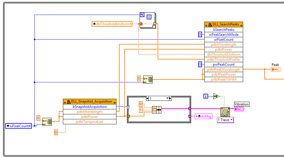
I had a device that could do 5000Hz sampling rate to get a spectrum each sampling. I put it in a while loop with vi Peak Search to find the spectrum peaks. Therefore, I would be able to get the value of 5000 peak seconds. However, the truth is, only, I could get a value of 40 peak per second. I guess there could be delays on the tops of the research.
Can someone tell me it would be possible to eliminate delay separating the part of sampling and part of the analysis? I think two while loops, first one collects all the spectra and the peaks of a seachs second. But do not know how to temporarily store data between these two parties.
It's a great idea! It's called a design ' producer/consumer '. LabVIEW is an example and a model if you want to give it a go. We are standing if you need assistance!

You have to invent it independently, however.
-
Where can I find documentation for OpenGL ES and bbutil.h
Sorry if he asked and answered, but I can't seem to locate any actual for OpenGL ES documentation such that it is implemented for the Playbook, but also the functions of bbutil. I got a flavor by working through the examples of programs, I have a lot of questions.
Any guidance would be appreciated.
Thank you.
Thanks Peter,.
I've been on this site before looking for something, but could not find documentation. I guess I don't watch enough hard because at your suggestion, I've looked again and found this
http://www.OpenGL.org/SDK/docs/man4/
That's more what I wanted.
Now, things bbutil. Maybe I'm not looking pretty hard for this too.
Thanks again.
-
Drops eye and sample a color without his race (and vice versa) object?
Is it possible to sample the fill color of an object and apply to another object without tasting his race?
And vice versa- taste the contour of an object and apply it to another object without tasting its Fill Color?
Any suggestion is appreciated. Thank you!
Select the other object.
Focus the fill or stroke (depending on which you want to apply color to).
Shift-click on the fill or outline of the object that you want to copy the color of.
-
Need codes of the SDK and sample
I am in need of SDK and enjoy codes to connect my printer HP Deskjet 3525 of my own app (Android). Any help on your side?
Hi Claudine,
I suggest that ask you your question on The Forums Android. HP supports printing from Cloud Print, Eprint, and a few others, but we wouldn't support options for an application that you created. Perhaps you could contact the assistance platform company. For example, if you used maker apps to store , you could contact them.
Good luck.
-
Output of Pick and Sample & Hold DAQ
Hello
The VI I must do the following:
- Generate low frequency (~ 1 Hz) saw tooth (DAQ AO0) value
- Entry of reading (DAQ AI0), which depends on generated value (for simplicity I just connected AO0 with AI0)
- When some condition occur, immediately stop generating sawtooth and maintain the last value on AO0
For simplicity, "certain conditions" is realized as transition 20th the sawtooth on the threshold value.
The interaction between 'Génération' and 'Acquisition' loops is carried out with the help of the local variable ""Stop generation loop "."
This Setup works perfectly except the following:
- When stops in 'generation loop' , value of production data acquisition is not equal to the threshold value (as it is supposed to be)
- The DAQ output value does not depend on threshold... threshold value is set, the output is about 2.2V (ordered on oscilloscope)
Any suggestions welcome
Concerning
Pavel
Pavel_47 wrote:
What could be the reason for this inaccuracy?
You have a race condition with the local variable when the variable is read before the release gets its new value. That's why the loop iterates again. Thus, you should use a flat Structure of the sequence to force the local variable playback after you the value of production.

Maybe you are looking for
-
This email is to inform you that your e-mail address has won you nine hundred and fifty thousand dollars ($950,000.00 usd) and a 6PLUS, MJLQ2HN/A MacBook Pro from Apple IPHONE) for this promotion of lottery of the year 2016, which is organized by the
-
folder shared between the administrator and guest user
Hello I am trying to hire someone to work for me, using my computer... It will record both use comments, but I need it to access some of my files, for example my quickbooks etc... Is it possible to have a shared folder, or in some way to grant access
-
Hello. I was checking to see if all drivers are avaiable for Equium A60 but I can not find on this site is correct? And there everyone out ther eupgraded A60 to vista yet?
-
Please can someone give me a solution to this problem? Thank you I also have my HP Envy 5530 listed twice on the HP homepage, I read a post above about fax issues. I would do the same set as resolved upward earlier? The changes will bring changes
-
I hear a lot about 32 bit 64 bit verses when it comes to vista and windows 7 printers. I have desktop computer with vista and a laptop with windows 7. I have a kodak 5500 all in one printer connected to the desktop and I can't print or connect to the