Filter marked graph (Graph Draw) XY
Hello
I have a question about a XY Chart data "filtering", please see the attachment.
The graph shows a few examples of data (white route) and a red field 'balloon' (you can press the left button of the mouse
and drag on the chart to draw the red path).
My need is to get all the samples inside the red ball, but now I'm stuck with it!
Any ideas?
(The attached VI is saved by LabVIEW2009 version)
Tags: NI Software
Similar Questions
-
Hi all. I'm a Subvi for a work project. My boss and I have run out of ideas and the drawing of the date deadline near!
I'm a noob to Labview, but I'll try to explain what my Subvi (or should do).
Basically my Subvi bed 24 channels of data of a VI. My Subvi should then turn these data items in a table and 24 separate bars on a bar chart to represent the voltage level of each output channel.
This he does, however, the chart shows only 20 channels and not more.
I know for a fact that the Subvi receives all processes and 24 channels (if that's the right word) the 24 channels self all the way to the end. But no matter what I do I can't get the graph to display the last 4 channels.
Myself and my boss (who know a lot more about Labview than me!) are stuck. Help, please!
I have attached my Subvi. It is commented, so hopefully it will be much easier to understand by looking at it rather than me try to do awkward attempt to explain in words! (Test 2 bar chart)
I've also attached the orginal bar graph VI that I adapted to my Subvi (bar graph example)
One last thing: "bar chart sample" was performed at LV 10 and "bargraph Test 2" was performed at LV 8.6 - because it had to be compatible with the previous VI. Sorry! (Bloody labview and non-problemes compatibility!)
Your board location only 10 items, so the loop place will turn only 10 times and not 12 because of autoindexing.
Try something like the joint. It's about the same as your code. To change the spacing of the x-axis, change dx, no need for the array of locations)

-
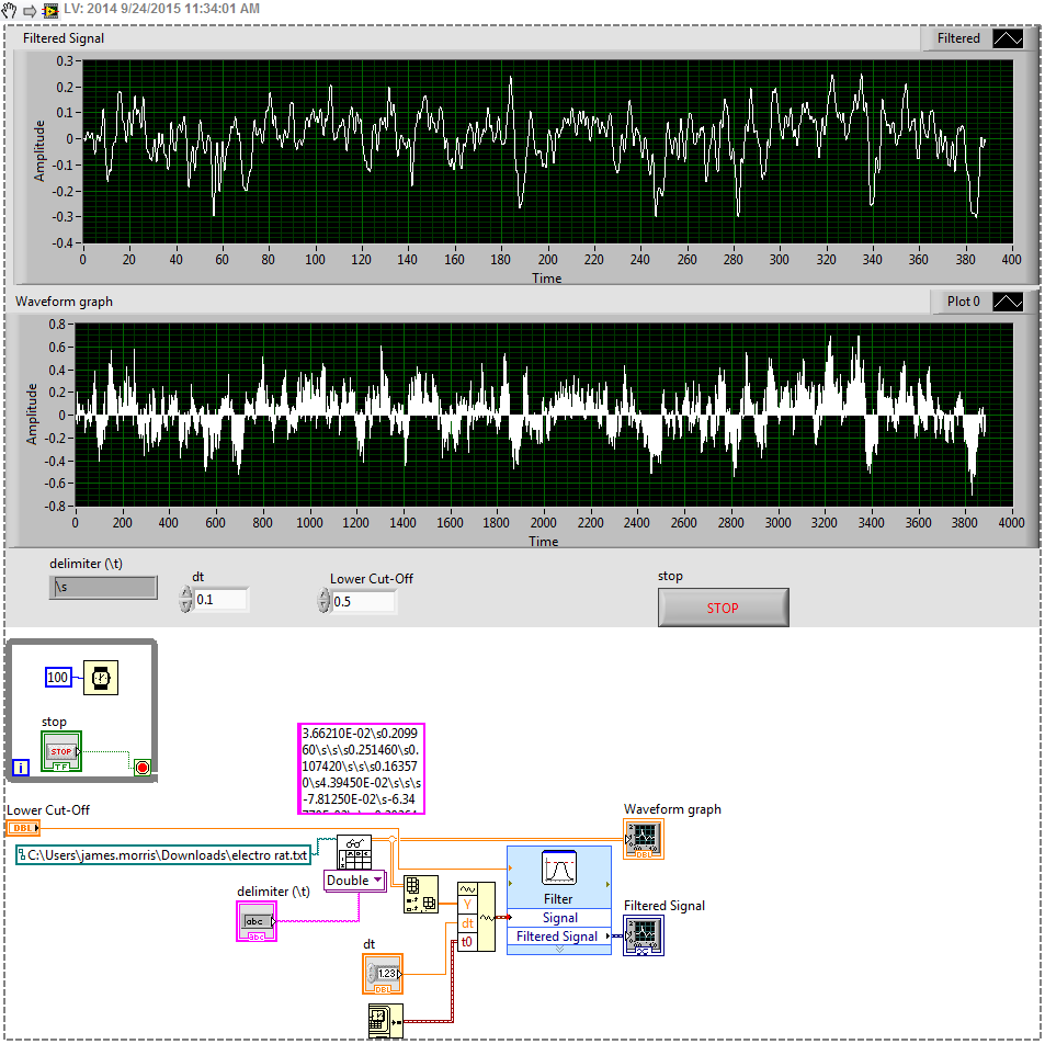
Help: Cannot filter a graph of function text
Hi all
I have a text file that I use to generate a graph and it works well. However, when I try to connect this table on a waveform to build it shows a wire broke (as shown in the image below).
I added the waveform build because it won't let me filter the signal directly from the table. I found this solution here http://goo.gl/wjacvO
How can I filter my signal using this function? Thanks in advance.
FYI, you must assign the default values where you work when you share a code. Your delimiter is '\s' and I have no idea what is your value of dt.
You should play with your cut filter to match your data rate. It has been set to 100.
I did work with 0.1 0.5 switching and dt:
-
I do a simulation for a displacement of the robot vehicle, so I have three exits, where two of them are the coordinates X and Y. So I wanted to take these two outputs to represent them on the X - Y graph so who see the graph is a point moves on the XY graph, drawing a line or curve regardless of the ground until it reached a point selected, the program stops when the condition is met.
My problems are now:
- I try to build the graph and what I have, this is a change in the X and Yscale with the change of my values, but nothing is drawn inside the chart.
- the other thing is that I can not put a desired point fixed on the graph, so when moving plot reaches the desired point the program stops running.
As a note when I active execution of climax, I found the program do what I want, but I can only draw on the graph.
File Untitled is a simple example of what I've done and untitled 1 is a part of my real code.
My guess is that because you're drawn only a single point, the loop runs so fast that you can't follow every point. That's why you can see when you turn on execution highlighting. Add a delay if you want to keep the single window approach. Otherwise, wire a constant false to Reset? entry on the XY build chart and you will be able to see all the points.
PS how in the world you are so blindfolded son.
-
Beginner LabVIEW - XY graph and audio files
Hello
I am very new to LabVIEW. I'm doing a program as follows:
- The LabVIEW VI to simulate two temperatures of entry.
- You can simulate each of them through a random number generator (be sure to keep the numbers in a temperature range of imaginary), or if you want to, by reading the values of a file.
- The Panel should, at a minimum, instantly showing each temperature (e.g., using a digital display), a graph drawing each temperature with time and an indicator (for example an LED or the counter number) to show that the temperature has exceeded its threshold.
Now I have the generator of random numbers and Boolean lights according to work properly. However, I recently added sound if the temperature drops too low (i.e. when the blue led shows) or too high (when the red lights). It works well, however, for some values sound custom ring, for others it will be. For example, three values in a line could show who are all under 16 years - the lower limit, the blue goes light on however the noise could only ring - its my default windows sound. Can anyone see anything wrong with it or offer me a solution?
Then, the XY graph. I feel that I don't get the right settings in there. I want the number of seconds on axis through the temperature values on the x - y axis. The temperature values initially came out huge by default, I have not changed the name of the axis but theres no graphics if I resized the axis myself? In my view, that I've not connected properly maybe? Also I really think I have somewhere went wrong with my reading of axis x, maybe I have the wrong time function in the control panel? I amn't familiar with boolean or or how to define true/false?
If I wanted to use 1 LED that could change in three different colours (red for high green, temperature temperature normal and blue for low temperatures), how can I do this?
Finally, someone has suggestions for the user interface, to make it look a little more sophisticated?
Thank you in advance, attached file.
First of all, you want to work on both your temperature at the same time and display them in separate indicators. Secondly, I am sure that your beeper goes with each temperature taken. You want to put the tone within a business structure to make it sound when you have any out-of-range condition.
So in the end, I'm sure you want a Setup like this. I'll leave some work for you to do. You are not nearly enough to pay me to do your work for you.

- The LabVIEW VI to simulate two temperatures of entry.
-
I think that a few people asked about this problem, but none of them seemed to have an answer so I'm re-posting.
It is thus the blur filter and mask to work in the code
var blur: BlurFilter = new BlurFilter();
blur.blurX = 10;
blur.blurY = 10;
mask of the var: Bitmap = new Bitmap (...)
var shape: Shape = new Shape();
shape.graphics.beginFill (color, alpha);
shape.graphics.moveTo (100, 100);
shape.graphics.lineTo (...);
shape.graphics.endFill ();
Shape.filters = [blur]
Shape.mask = mask;
bitmap.bitmapData.draw (shape);
But the result is not what I want. Please see the image below:

Do an another pixel bitmap and copy using the mask works but it makes any application very slow.
How can I hide blur filter using a simple draw?
The difference between the code I posted, and what you have here, is that you apply the mask and blur to form, while I applied the blur to the shape and the mask to a container of the form is inside. It is because for a given object, filters are applied AFTER all masking, but you want the opposite. The only way to control the order in which I don't know if it is to create more layers.
In other words, change the last code you have posted like this:
1. create a container for the form:
var container:Sprite = new Sprite();
2 Add the shape to the container:
container.addChild(shape);
3. apply the blur on the form and the mask to the container:
shape.filters = [blur];
container.mask = block;
3 trace the container for the bitmap:
bitmap.bitmapData.draw(container);
To produce the image you want.
-Aaron
-
Hello users of Labview,.
I have a vi that records mass gains based on time. The problem I have is that I want the time on the x-axis in seconds but somehow the vi records the data quickly and time is certainly not seconds. It is not more milliseconds. I have attached the front panel and I need help to make the vi to register data based on real time (in seconds).
Thank you.
-Myriam
the waveform table each time you read your signal, plot you your data.
The waveform graph draw you tables of data. If you don't want to set the announcement, then, use the dashboard wafeform and time your loop, so you'll have your measurements in a time of definide. If you time your loop, the computer does work as soon as possible, and you cannot guarantee it will read your signed at regular intervals.
-
Digital output with timer (Simulation)
Hello everyone, I just found out how LabVIEW program a week ago. I try to do a simulation of digital output by LabVIEW (my attachment). In this simulation, I have a slider as an input (0-10 V), two digital controls (upper limit and lower limit), a waveform graph draw these 3 evaluates and two Boolean LED (P0.0 and P0.1) as indicator. In this simulation, you can fill any number (between 0 and 10) in numerical order as a limit for your entry cursor. If the entrance of a cursor exceeds these upper and lower limit, then the Boolean LED lights, P0.0 so exceeds the upper limit, and if P0.1 exceeds the lower limit. The problem is that I do not know how the timer for those Boolean LED. As an example:
(1) make an entry of cursor,
(2) if entry (1) exceeds the upper limit, P0.0 lights for 5 seconds, then turn to during 10 second.
(3) if only 10 seconds, you change the entry back to normal (between high and low limit) then P0.0 will stay turn of until the cursor entry exceeds the upper limit again,.
(4) If, in this second 10 you has not changed the entry (the stay exceeds the upper limit) then P0.0 repeats the process (2) until you the entrance to cursor back to normal.
(Same process for entries exceed the lower limit).
Can you help me do this timer? Thank you

Concerning
Juventom
Hello
If you don t mind I would just give you some advise to your code. To determine the data stream you can also use only the error wire connected to the loop. So Don t you really need, it's beter not not to use variables. For your solution, you can use something similar to what I tried for the upper limit in your program. It is added as an image.
Hope it helps
-
I use DAQmx Read (analog 1 wfm NChan NSamp d) .vi twice, once to read Dev/ai0 and Dev/Ai1, two analog inputs of a PXI-6052. I can do a waveform graph draw one or the other, but I want both of them to appear on the same waveform graph. How can I do this?
Thank you
Kevin
Use a table. See the example with LabVIEW.
-
Pls helpme implement canvas and BufferStrategy on my old 'self made' buffer
Hai all!
As suggested by me cardan2 here:
I tried to implement the Web and BufferStrategy in my project.
My old method of buffer selfmade was as follows (note: the explanation is shortened):
-J' use to extend a framework
-J' I create a BufferedImage with that
-J' made a class to manage the buffer (BufferManager)Image buffer = this.getGraphicsConfiguration().createCompatibleImage(buff_xo, buff_yo);
- Then I start a regular thread with a class that extends TimerTask, which is practicable (CoreThread)BufferManager buffMan = new BufferManager(buffer);
-I overloaded directly image update() paint (g) methods and frameworks write "buffer" on the graph of the imageScheduledExecutorService core = Executors.newScheduledThreadPool(1); core.scheduleAtFixedRate(new CoreThread(buffMan), 5, 16, TimeUnit.MILLISECONDS);
-at the end of my son, when I need to update my screen, I call the paint (g) of the image method.@Override public void paint(Graphics graph) { // Drawing everything from the buffer, and removing flicker effect graph.drawImage(buffer, buff_x, buff_y, null); } @Override public void update(Graphics graph) { paint(graph); }
And it's practically how my work... as you can see, I'm bored a canvas and a BufferStrategy.
Watching this tutorial http://www.javalobby.org/forums/thread.jspa?threadID=16867
I see that he uses to set up of the canvas (easy, that I can do it) and then get the BufferStrategy with her.
After that, it gets the BufferStrategy graph and use it in the threat are paintings on it.
It removes the graphic and uses the BufferStrategy show() method to paint the buffer and update of the screen image.
My problem on the implementation of BufferStrategy, is that I often use the "buffer" Image everywhere in my code (expecially when I need to make calculations with his size) and not simply its graph.
So to implement the use of BufferStrategy, I should send it anywhere in the BufferStrategy where now to send the Image buffer?
And then should be enough to call the show() method of BufferStrategy instead of patint (g) to the end fo my thread, when necessary to screen update?
Thanks to you all!Patcha wrote:
But my problem is Graphic2D object contains data about the current size of the traced... t-zone - it?
I do a lot of calculations and there on the size or adjacent buffer of collisions.No, but the BufferStrategy also does not deal with things; the canvas has dimensions.
I'm pretty lazy in this regard and I tend to have a singleton in this class that can call application components to understand the details of such as dimensions. Class singleton has then access to things such as the frame and the canvas, the rest of the code should not know they exist. All drawing is then made to the GUI of base, which could be the BufferStrategy backbuffer or, for example, that of an image from scratch if I want to make a composition before I blow the final result to the screen.
Some people will condemn me for the use of a Singleton, but I don't like much about it really ;)
-
Hi all
It's my first time programming in LabVIEW and slowly grasp the concepts I'm found stuck on a very simple task (more likely). I have two flowmeters hung in the series that I get speeds of, I can take the average of the two for better accuracy with our readings and the value of display on the front panel.
Here's where I start to have problems. The flow through the meter is not continuous, we will turn the market circulation several times throughout our tests. Currently, it is very good and I don't see my average flow when the meter is turned on and 0.0 when there is no flow, since he constantly records. Though, now I need to display the total volume that ran through the flowmeter during operation.
Thus, for example, we spend on the stream ("draw") to 3.0 GPM for 0:02:30 then the output reads 7.5 gallons and would reset this total to 0.0 before the next draw started. So, in principle, we would see only the total for each series of draws. Although, it would be useful to keep a running total of the number fired during the entire test.
I know that to create a running total, I can use a while loop and a change to the registry. This, I think, will give me the total gpm on a period of x cycles, which I could then divide by the number of cycles and exit the average flow in 1 minute (mean flow available1). I have the following program resets and repeat this loop until a minute and adds this number (flow2) to a total accumulated for my overall volume? I don't know how to start / stop the while loop based on when I paint, unless I'm somehow save the stream of 0,0 and when the while see what it stops? I don't know there is a different (better) way to do this that is constantly running and recording?
Any advice would be appreciated, thanks for your time.
I would use the GPM 0 as your marker in the draw is completed. Yes, keep a record to offset for the amount of flow. Keep a record to offset for the number of samples taken. You will also need to know your sampling rate. It's just a simple multiplication from there. A simple state machine should be able to easily handle this.
-
No idea how it works technically? Is it like a 1 second traction? Or is - what really push?
Please explain :-)
Thank you!
Sapag
Sapag wrote:
No idea how it works technically? Is it like a 1 second traction? Or is - what really push?
Thanks for asking, because it made me look it up. It seems to be implemented via an IP connection constantly open to your Palm Pre to the messaging, as well as control IMAP server, INACTIVE, which is issued by the Palm Pre and responded to by the server of mail only when the following message is available in. So, at the expense of a single IP connection over the phone being held open by anyone, it is really a boost non-bureaux to vote and not a closure, mark, 1 second draw. There is complexity involving unreliable connections, gateways, and similar and 15 minutes using NOOP keep alive.
The downside is that for my phone at least and I haven't changed anything, I have stopped to see notifications of new messages for the past two days. GRR.
More details on Push IMAP and IMAP IDLE here:
Push-IMAP - Wikipedia, the free encyclopedia and IMAP IDLE: the best approach for 'push' email
-
E10 campaign canvas: exclude the bounce/unsubscribe
Hi all

This is one of my campaigns. I know that these contacts in 1944 in green at the top right 'Email' are contacts do not sent mail because being marked as excluded from bouncebacks or be unsubscribed, by master exclude or overall exclusion. Would it not be better to exclude these contacts in the segment? Then you would have the precise number of marketable contacts in the segment. And if yes: how to proceed? Whose filter criteria possible is correct: 'Marked as hard Bounceback' with the operator 'now '?
Thanks for sharing your best practices.
Best,
Michael
I always exclude hard bounces and overall cancels his subscription in my segments so I have a more accurate count. I use the filter 'Marked as hard Bounceback' with the operator "right now" as you said. This works well for me. You can even set up a segment with these filters model so that you don't have to configure them manually every time.
-
Draw two graphs, a simple graph
Hello. This is my first time using the command and the simulation. I want to draw two graphs in one graph. It seems that I have to use together and to build tables functions but I don't know how to draw them. The points x and y (2) are only defined by a single set of points included in the defined table. The points x and y (1) are the results of another formula, but the two parcels would fit in the same location in a single chart. I hope that my question is understandable. I attach a portion of the model I want to be plotted.
Thank you
Hello
You can try something like that. Check the attached VI.
Kind regards
Amine31
(Give congratulations to good answers and Mark as a Solution If your problem is resolved
 )
) -
Is it possible to draw two lines in a single chart using Grapher? If so, how? If no, then how I can draw two lines or more?
Yes, click on the sign in lower left to add another equation.


Maybe you are looking for
-
Hello. I have a KDL55NX810 and I started to see white spots in different parts of my TV always on the same place. One of them is more visible during the black screen. When I regularly watch TV (cable) of the part where the tasks are the color appear
-
Satellite P100-202 - screen freezes
Hi, first I would like to say that I think that it is a recurring problem of Toshiba, because I have a friend who has exactly the same thing happens to the Toshiba PC. Here's how it goes: While working on the laptop / PC, all of a sudden the screen w
-
Shell Lottery International, Inc.®. Is it true that they give to earn money?
SHELL LOTTERY INTERNATIONAL, INC.®. is it true that they give to earn money?
-
Help me get the icon internet options works again in the Panel.
I followed the Instructions given by nass1 and saves the bits as said, but there is no other instructions than the link below http://answers.Microsoft.com/en-us/Windows/Forum/windows_xp-performance/help-me-get-Internet-Options-icon-working-again-in/b
-
How to recover the admin account
original title; account Some how my administrator account has been deleted and my single user account is only limited accessability. How admin account back?