FPGA: DC - RMS measurement vi
Hello experts!
Can someone tell me how the "DC - RMS Measurements.vi"? Specifaclly, I would like to know if it returns an average commute or work on blocks of data, as an average lets say more than 1000 samples and only returning a single value/1000samples...
Best wishes
Luke
I think you are referring to ms and RMS measures VI on FPGA Math palette & analysis? It operates on blocks (or frames) data, it will return a valid output for each nitrogen. As mentioned agomez, you can check it by analyzing the valid output signal when running in Simulation or in workstation mode.
An average continuous measurement would be at hand, but requires also to store the entire frame, so you can subtract the effect of the oldest point when leaving the window.
Tags: NI Software
Similar Questions
-
RMS measurement over time "long".
Hello
I want to measure the RMS of 'complex' waveforme, so it is quite difficult to calculate from the graph. I use a power - gauge. My proplem is that the result is digitally displayed and the result changes from time to time. the signal is periodic with a time - period of 112ms. is there a way to graphically display the RMS?
THX
Hello stenzer,
I don't know I understood exactly what you want to do, but I think that the functionality you need is the "postprocessor. With this function, you can perform calculations on the results of simulation and display them graphically. You will find the postprocessor in the simulation menu > postprocessor.
-
Repeated values in the measure (FPGA, cRio) signals
Hello
I'm seeing repeated in my measurements values and trying to determine the cause
I read a single analog channel from a module NI 9201. In order to eliminate the noise, I averaged several samples by using the ms and RMS measures VI (shown in "FPGA Code.png")
An example of repeated values appear in the "comparison of Signals.png' for both the original signal and mean
The sampling frequency of the NI 9201 module for a single channel is 500 kech. / s, which I also checked by measuring the sampling frequency (the code for this is also reflected in "FPGA Code.png")
On the target of cRIO RT I record these values in a loop timed 500us using 1 MHz of the cRio clock
For the ms and RMS measures VI, I tried several options, for example:
-500 US measurement time, sample rate 500 kech. / s
-450 US measurement time, sample rate 450 kech. / s
-400 US measurement time, sample rate 400 kech. / s
-US 300 measurement time, sample rate 300 kech. / sEach of them give measurements with repeat values to varying degrees, for both original and average signals
Any suggestions?
-
FFT on several channels in FPGA
I have a client with a 9076 (Spartan-6 LX45) who wishes to perform the FFT on several channels of a module of 9205.
I never run FFT on several channels and never run out of space on the FPGA before, but I strongly suspect that this could change that. Before I start to code this and play, someone can experience with this scenario - that offer you an optimal architecture / let me know how many channels can I expect to treat?
Hey Jed,.
As someone who has done a very similar application, but with the DC/RMS measurements, I can say with confidence that Yes, this is going to change that... How many channels your client wants to do and what kind of flow? I was able to get up to 64 is going, but it took most all of the fabric, and I had to write my own calculation of DC/RMS multiplex VI. So under a flow of course (I think we had each channel was updated to 1 Hz with 1000 samples per channel). Therefore, when writing a VI that multiplexes across all channel data, you could theoretically get many channels out there, but you sacrifice a flow.
Basically, I modified the existing Express VI to store its State in BRAM between each call and he's travelled to the number of channels * samples I was doing. Not terribly difficult, but your time trying to find a good balance for the given application.
-
Strange problem with my FPGA Code
Hello
I am running the following program, but I am facing a strange problem:
-I can read all analog and digital input and write on the outputs analog (I measure the tension that I write on the map of the AO)- But the valves I have connected to the analog output, flashes a red light (which, according to the data, sheet means the electrical signal I send to them via the module AO is incorrect)
-However, if I delete the ms and RMS block and do not make any average samples, but let all even (still two loops and two of the nodes separated from FPGA to e/s), the valves are operational and flash not a red light.
I have a cRIO with four modules:
-1. The (Mod1) AO cards
-2. Map of HAVE it (2)
-3. DI/O card (Mod 3)
-4. Map to HAVE secondary (Mod4)I currently have two loops on the fpga all-in:
-' Hand Loop (ML)': reads and writes I/O cards 1-3, with an expectation to 300us
-'Top pressure sensors Loop (PACKAGE)' reads two HAVE the fourth module (Mod4), with no waitingThese two loops are indicated in "fpga - part 1.png" and "fpga - part 2.png".
The settings for the ms and RMS measures VI, as well as the façade are indicated in "fpga - part 3.png".
The second loop uses 12002 ticks to run, the first loop use 160 ticks to run
Previously, I had a similar problem which was fixed by setting the initial values indicated on the front cover for the analog output to the valves.
Currently, I have not any target VI race and I'm only using fpga VI
Any suggestions? Thank you!
-
PCI-6110 - calculated resolution RMS
We have a requirement for the resolution of measurement of voltage AC RMS. I am in a position a repetitive alternating signal with 512 samples on 1 cycle using the range full scale. I then calculate the value of these data. What is the effective resolution of the RMS measurement? Should not 512, 12-bit samples (signal varies for each sample) produce a measure of 12-bit resolution? How can calculate the actual resolution of bit RMS?
I don't see how it takes into account the benefits obtained with various LSB errors between samples.
The best I can determine via Google is the increase of the resolution for a simple average is the square root of the number of samples. So 512 samples would result in improved time 22.6 (adds 4.5 bits). The improvement of a quadratic average is probably different (less), but my test here with real hardware is in this stadium. Google also revealed that some applications intentionally add a small amount of random noise, resulting in a dramatic improvement in the calculation the resolution.
-
Duration of the impulse in labview FPGA
Dear
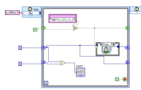
can help build a FPGA lv to measure the duration of the pulse
My first lv VI is illustrated below for Spartan 3rd kit the but its fail to work
Michel thei change operate?
for the case of structure in case of false the old value is moved instead of tick counter
Best regards
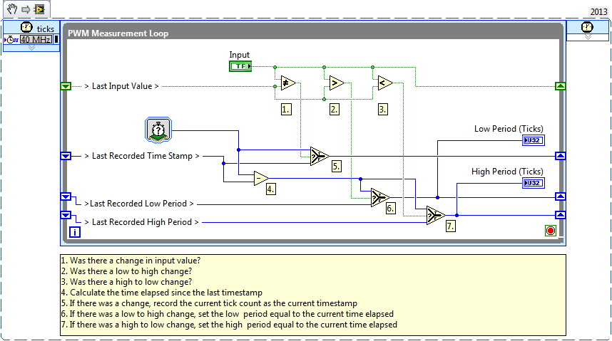
It is also an example in the finder NOR example on exactly how to proceed

You can search pulse to find it, or use the snippet below:
-
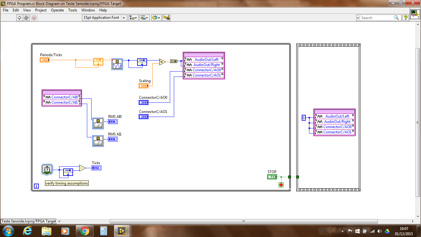
Plese help me!
I'm reading the value of the RMS of a sine wave input Myrio (AI0 and AI1 - Conector C), but I can't. I need only read this value and convert it to power at the end of my Masters. I do the integration of a Flight Simulator (X-plane) with Myrio and a hydraulic platform. Follow my code.
in order to use the molding based RMS, you must define the RMS function parameters to match your use of sample time case rate and measure to coincide with a whole number of periodic cycles or set the option "apply the hanning window" on the express VI.
Is that what you underlyuing periodic signal? How often?
Use the timer function to loop to the rhythm of your loop and use this frequency in the configuration of RMS.
calculate the time to an integer number of cycles of your friequency and use it in the configuraiton of RMS.
Remember, you get only one value of RMS measurement by period using the NI RMS function.
very often, we check the FPGA math using the same algorithm with known in labview for high level data sets. Maybe you can try also.
-
GUI is unresponsive upon receipt of data
I am relatively new to Labview and still getting used to the model data flow programming. I'm using LV as a control panel for some software and hardware running on an FPGA for a prototype I've created. Communication with the FPGA is made using the UART and seems to work correctly. I have however the problem as my command buttons unresponsive in certain special occasions. I think that the best way to go here, it is that I explain what must do my program (and what I think he should do), post my VI, explain when it blocks and I hope someone can help me to identify the problem.
As I said LV is supposed to be the Control Panel, via this Panel the user can change some settings and start/stop the measurement. Orders should be sent to the FPGA (ZYBO Board for those interested) which applies the commands and sends return measures.
I founded my VI on the simple state machine model and build the rest from there. I tried not to use too variable, as I read that this breaks the flow of data model, but sometimes I could not find another way.
It is thus the VI should work: after initialization, it should be waiting for the event status, pending a change in the value of the start/stop button or the button exit. Every second, a timeout event occurs and LV checks with the FPGA (and sends the commands to the FPGA). If the Start button is pressed the FPGA starts to measure in each packet, it returns the FPGA will tell how tall are there are still and send the data 60bytes to LV most of the time the UART communication is the bottleneck and the number of measures will begin to grow. During this time, however, I am still able to change the values of the controls I have send to the FPGA (I like). If I press the start/stop button once again I send the command stop to the FPGA, which means that it will stop measuring, but always send data to LV I think VI makes a loop on the same States when it measures (communication-> button control-> manage data-> communication). Meanwhile however the GUI does not appear to meet my keys, it won't let me change the commands I send or even use the exit button. This lack of response remains while I get data. Once the number of remaining measures hits 0 (the variable 'name' in VI) goes back to the State "in anticipation of the event" and at that time there my previous keys are executed. (So let's say that I pressed the convenient stop button are still some measures should be sent, if only the moment where I press the exit button it will not respond but once the communication has been completed, it will record key press exit and exit the VI.)
I tried to avoid working with timers since communication is the bottleneck for the moment, this is the reason why I will not return to the State "wait event" once the measures began.
I hope my explanation is clear, that otherwise, I'm happy to clarify even more (or reword if necessary). A summary of my problem:
During the time that I am able, and receive data I have to loop through the same States that when I stopped position and am simply receive data ("communication-> button-> handle control') data-> communication. When I am able the GUI is always sensitive and when I stopped measuring it is not. I hope that someone can help me to find the problem and we hope to offer you a solution.
Thanks in advance!
PS as I said that I am relatively new to programming LV so if you see some other "nono" you can also tell me to improve myself.
It is the nature of the beast when it comes to State Machines. This is why if you perform operations of a lot of time, you will need a parallel loop in order to accept user input. Look in the architecture of messages in queue manager that comes with LabVIEW. It is essentially a structure of the event in a loop that sends messages to another loop through a queue. The loop (slave) receiver is on these messages and takes as long as he wants without interrupting the user input.
In other news, it seems that you used the simple state machine good enough popularize and how to configure reports and other things. Here are a few tips none-the-less:
- You don't need the structure of the sequence. Your code already follows the stream, so you don't need to create separate data sections. It compartmentalizes the code and ultimately get rid of the ability of LabVIEW to perform some of these operations in parallel to increase the speed of execution. Structured sequence should be used when you do not have a way to control the operation order (by adding a wait between two operations, etc.).
- You can move the control command structure of the event and manage changes in value through a shift register. There is overhead associated with reading the control every single loop.
- Once you look into the QMH architecture, you will be able to get rid of all the Boolean reading of output you have in each case. The structure of the event should contain all your controls to optimize the functionality of input from the user.
- You have the cluster of error through each case because the model put there for you, but you do not use. You should the dishes your clusters of error through so that you know if you made a mistake somewhere. Your initialization and Comm States should have it wired for sure to see if you have a series being undermined.
-
Dear jury,
I wonder if an alternating signal operating at the limit of the range selected on the 6008 have on beach? Is the limit of the range a dc value; or is it over the range capabliliy built in AC RMS measures? The manual is not clear on this. Someone at - he delt with it?
Thank you very much!
Mike
Mike,
the 6008 is not a method of coupling of special entry. Therefore, the given maximum scope is a DC value.
So if you select 5V as maximum range and have a sinusoidal signal with Vp = 2V and 4V offset, you will cut the positiv to 5V wave.
hope this helps,
Norbert
-
How to measure the frequency of sampling (s/s) in LabView FPGA?
Hello
I am trying to find a way to measure the sampling frequency (s/s) during which I read from analog input in LabVIEW FPGA. I know that the sampling frequency is specified in the data sheet of the module HAVE, but I want to measure in LabVIEW.
Any suggestions?
A screenshot of the example code would be greatly appreciated
Hey phg,.
If you have some time loopand in this loop, you export a sample by iteration of loop via an I/O node. You can't out two samples on the same I/O node within an iteration, it's always one!
So if your loop takes 1 second to run you have a sampling rate of 1 Hz output. The same goes for sampling of entry. How long your loop takes to run can be calculated as explained above.
Samplerate [s / s] = 1 / [s] while loop
-
Many many FPGA measure frequency
Hi all
I'm trying to measure the frequency of certain PWM 50 signals that only goes to 300 Hz. I use the R-7833. Attached, that's what I use to measure the ONE PWM signal. Now, the problem is: is it possible to use the same code to measure signals PWM 50 without copying and pasting the same code 50 times. Note: I tried to make the Sub - vi, but did not.


Hi Bladhart,
It is a good deal when the movement of the I/O node structure and loop outside the Subvi helps make the code more modular and scalable. NOR has posted guidelines for the creation of basic functions (IP) FPGA for re-use.
Here's and example of how you can implement this period measurement VI in a way that is more scalable.


SUB-VI TOP-LEVEL VI
See you soon,.
-
Measure cc using BasicDC-RMS and AvgDCRMS
Hello
I intend to calculate the continuous component of a noisy signal. Both the BasicDC-RMS and AvgDCRMS vi will give it the output under the waveform but how to get them as a constant instead of show with the waveform. The domain controller is component of the signal obtained will be used for the calculation later with a formula.
Thanks in advance.
Use Mean.vi of mathematics > probability & statistics palette on the component Y of the waveform.
Lynn
-
RT update to include new Variables of FPGA/controls
I feel ridiculous to have to ask the question, but I had to face for 2 hours now nothing works. I have a target FPGA and host RT that work very well together (sbRIO-9636). I recently decided to add 4 new controls (analog input) to the sbRIO. I added the to the FPGA module and they measure and read very well. However, when I try to use the ' read/write of FPGA control' on my RT host these new four variables do not display upwards. I created variables shared for them and deployed them, but still nothing. When I perform a variable node shared, I can see them as options, but I can't access their analog data in the RT vi module. Should I perform a refresh? I ran the RT and the autonomous FPGA and they run fine. I'm just not get all the data passed to the host of the RT.
Any help is appreciated.
gerin99
You should also check the FPGA reference that you use in your code of RT. If the reference points to the previous bitfile rather than your news, then the controls will not be displayed because they are not in the old file. This has triggered me a couple of times in the past.
Warrior of wire
-
Broken the FPGA VI but the empty error list
Hello!
I'm trying to run a vi which includes a 'Open FPGA VI Référence' function. However, an error and it says that "not compiled FPGA VI. When I try to compile the FPGA VI a message saying "The VI is broken". I try to run the FPGA and when appears in the error list, there is no error or warning in the list, although the name on the fpga includes the Red 'X' ('show warnings' is checked). Any help?
I'm using Labview 2013.
Pablo
Hi Pablo.
Sorry for my delay in responding, you managed to get the respected FPGA.vi yet?
To answer your questions, if the project is ok with an empty FPGA.vi, then in theory, your hardware is configured ok. However, due to the vi being blank, you haven't tried to use one of the modules on your system, so it can introduce errors. The most common mistake is differentiation of mode Scan Mode/FPGA by installing the project in the first place. Also be aware that not all FPGA targets supports everything, for example some dislike for the rows that have an index to calculate the number of iterations, rather than a constant wired at the entrance to "n".
Out of curiosity, why you place every measure in the DMA separately and also specify address? Is there a reason you don't just place all the measures in a table and put everything in the DMA, then divide the table on the other side?
Generally speaking I don't think that incorrect programming should never cause LabVIEW crashing and you should always report the problem to the OR in order to take a look and see if they can fix it.
Hope that you managed to get your problem sorted and again sorry for the late reply.
Darren.
Maybe you are looking for
-
How to install and access the firefox on my android os?
-
My news story 'Date added' is now gone joined upward with the SYNC...
They are now all updated to the date of synchronization instead, and my story when I added a bookmark is lost, very disappointing... A way to solve this problem? Fortunately, although I used the files in my favorites and nothing in the files is still
-
Pavilion G6 2342dx, Wifi works does not after update driver recommended
Hello. I have Pavilion G6 2342dx running Windows 8. Yesterday, I used HP support assistant to perform some recommended driver updates. Among the things to day was the device of Qualcomm Atheros Wifi driver and the driver of HP wireless button. Periph
-
The HP C4680 printer can be modified to be used with wireless?
-
Have tried and tried can't print on adobe.