frequency of generation of impulses or daqmx 9.6.1
Hello!
I am using an NI USB-6211 to control a stepper motor. I need to generate a pulse train with the right frequency to an angular displacement of the desired speed. For this, I wrote an application in c# (.NET 3.5) using the NI DAQmx 8.8 library, and the application worked well. However, when I updated the driver for the 9.6.1 version, the same application (recompiled with the new dll) took exactly half the time to accomplish the same task. I didn't measure the output of the counter, but I guess that the generated frequency is twice more as configured.
Is there a bug known in this version of the driver or maybe I did something wrong?
Thank you!
You can reach the exit? Which of the following describes your situation?
- You get the desired number of pulses to twice the desired frequency. I still think it's unlikely.
- You get less than the desired number of pulses to the desired frequency. If this is the case, I'd be willing to bet WaitUntilDone wait not long enough for some reason any (check this by adding an additional wait time after waiting, but before you stop the task).
- You get the total number of pulses desired to the desired frequency. If this is the case, then it seems that the software runs just as soon that he had done before (which shouldn't be a problem, should it?).
Best regards
Tags: NI Hardware
Similar Questions
-
Frequency measurement of analog input using DAQmx C APIs on SMU-6341 map
Hello
I use Linux DAQmx and attempt to measure the frequency of analog input using the map DAQ SMU-6341.
There is an ANSI-C frequency measurement example:
/ usr/local/natinst/nidaqmx/examples/ansi_c/Analog_In/Measure_Frequency/Cont_Freq-Int_Clk-SCXI1126
However, the call to DAQmxCreateAIFreqVoltageChan results in the following error:
DAQmx error: selected physical channel does not support the type of measure required by the virtual channel you create.
Create a channel to a type of measure that is supported by the physical channel, or select a physical channel that supports the type of measure.
Property: DAQmx_AI_MeasType
Required value: DAQmx_Val_Freq_Voltage
Possible values: DAQmx_Val_Current, DAQmx_Val_Resistance, DAQmx_Val_Strain_Gage, DAQmx_Val_Temp_BuiltInSensor, DAQmx_Val_Temp_RTD, DAQmx_Val_Temp_Thrmstr, DAQmx_Val_Temp_TC, DAQmx_Val_Voltage, DAQmx_Val_Voltage_CustomWithExcitationTask name: _unnamedTask<0>
State code:-200431
DAQmx does support the function of the frequency on the map 6341, or should we use examples of voltage and calculate the frequency manually?
Frequency of HAVE it is a type of channel that has been supported only on the SCXI module name of the example.
You will need to use a voltage input channel and calculate the frequency manually for your device.
-
generation of signals using DAQMx.vi
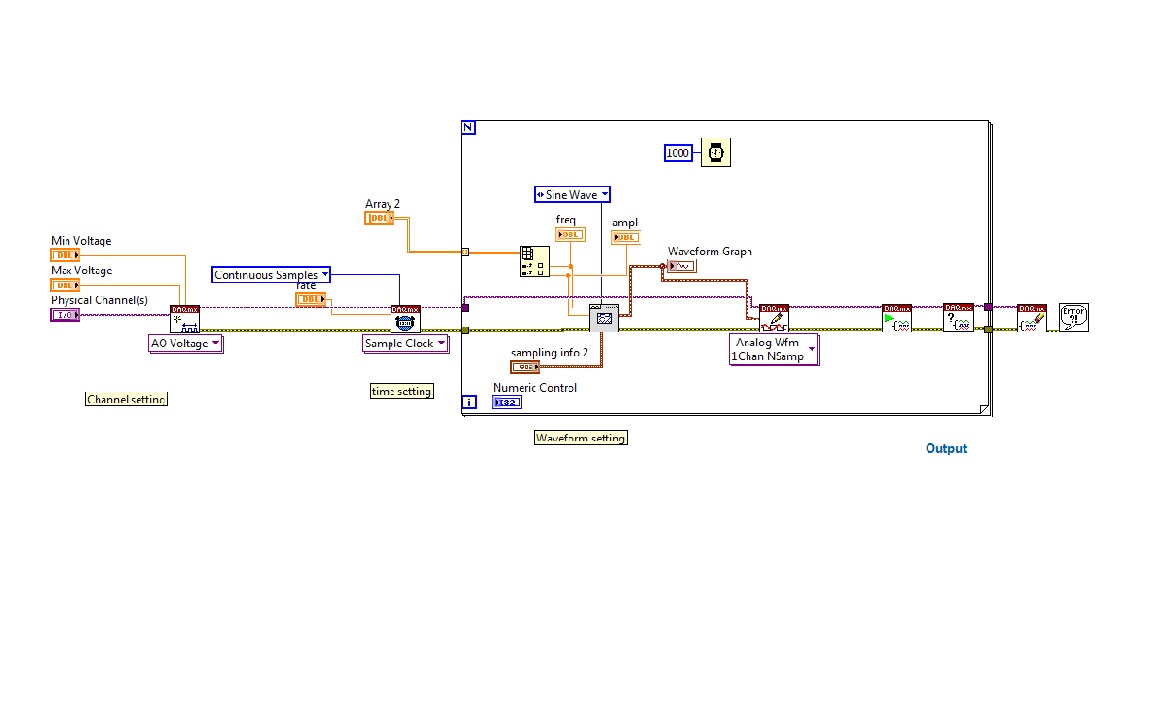
I'm trying to generate signals with a generator block functional VI, with a lop fill and table with values of frequency and amplitiude
as in the diagram below.
When programs run at the end an error message pop up
- Error-200479 occurred at DAQmx start Task.vi
-Specified operation cannot be performed with task is running.
-
Generation of impulses associated with Motion Control
Hello
I'm currently controlling a stage prerequisite microscope with Labview, through a serial port. LabVIEW communicates via the active X functionality to the control of the stage box.
I would like to be able to integrate a feature of external impulse generation in the system. So, I wonder what kind of material, I will need to do this? The pulse should be about 5 V in amplitude and in the range 1-20 Hz.
Finally, I wish to cordinate movement of my turntable of the microscope with the external pulse generation. Have some sort of feedback would be important as well.
Thank you for your help.
Mike
Thanks Dan. I appreciate your advice. I have also received feedback from my local field engineer and identified which device will work best for my needs.
-
input analog trigger on the door of the meter to measure the frequency of generation
Hello
I want to measure a frequency on the analog input, but it doesn't seem to work.
I'm trying to work with DAQmx with the use of the ansi c standard.
The first step, I've done was acquiring information on the analog input. With the use of a simulated device, it shows a sine wave on the entry.
My next step is to generate a trigger for the meter signal, but this doesn't seem to work.
I don't see how it is possible to connect the trigger on the entrance to the analog meter.
For the creation of the analog input and relaxation, I use the following code:
DAQmxErrChk (DAQmxCreateTask("",&taskHandle));
DAQmxErrChk (DAQmxCreateAIVoltageChan(taskHandle,"Dev1/ai0","",DAQmx_Val_Cfg_Default,-3.0,3.0,DAQmx_Val_Volts,NULL));
DAQmxErrChk (DAQmxCfgSampClkTiming(taskHandle,"",10000.0,DAQmx_Val_Rising,DAQmx_Val_FiniteSamps,1000));DAQmxErrChk (DAQmxCfgAnlgEdgeStartTrig (taskHandle, "Dev1/ai0 ', DAQmx_Val_RisingSlope, 0 '"));
For the creation of the meter, I use the following code:
DAQmxErrChk (DAQmxCreateCIFreqChan (taskHandle1, "Dev1/ctr1", "", 1 January 2000, DAQmx_Val_Hz, DAQmx_Val_Rising, DAQmx_Val_LowFreq1Ctr, 1, 4, ""
 );)
);)I hope someone could give me a hint.
I also tried the examples that come with DAQmx but well I know this are only examples to counter with the help of the digital inputs.
Thanks in advance.
Hello
You must use the exit event of comparison at the entrance of the meter. Change this property after the configuration string function.
DAQmxSetChanAttribute (taskHandle1, "", DAQmx_CI_Freq_Term, Dev1/AnalogComparisonEvent);
Kind regards
Bottom
-
generation of impulses PXI-6602
I am new user and I got pxi 6602 iwant to generate a 5 3.5ms amplitude 2.5 kHz and 2.5 offset I probably need to use 2 meters can someone tell me which wires I need to connect on CBS 68 device and how ican write this program?
Thank you for helping meIt can generate a ttl which means a pulse of 0 to 5 volts. If that fits your definition, then it will work.
-
Timed software a generation of impulses - USB-6009
Hello.
I searched for a reliable way to produce a pulse point by point with the USB-6009. My question is whether or not it is possible to produce such a signal without hardware timing or a counter as the USB-6009 supports neither. Is the closest I've come to produce a square with a very low duty cycle wave. However, what I would ideally look for is the ability to produce a single pulse inside a loop which I can go once per minute or more. Also, I would like to know what are the parameters I would be sacrificing to produce a pulse in this way.
I also have access to a function generator and as it seems quite difficult I will be probably triggering just its pulse function in the same way, but I'd like to explore this obstacle before moving on.
Thank you
Travis.
20 ms can enter the region where you will begin to see significant amounts of timing jitter. You really need to write your program and make some careful measurements - over a long period of time - to see how much of a problem you will have. Actual performance will depend on a lot of details: the operating system, other software process running in the background, and how the LV program is implemented. You must reduce as much as possible, everything else on the computer: no network, no antivirus, no Bluetooth or WiFi connection and so on...
Lynn
-
frequency of the digital signal 6009
Hello, how to generate the digital signal with frequency 50 Hz using NI USB-6009?
You can take a look at this:
Can I use a generation of impulses with the counters on the USB-6008/6009 case?
-
Timed signal generation TTL with the NI USB-6501 to be read by Arduino Uno
First of all, I want to apologize - I am very, very new to LabVIEW and brand new to the development of the software of control equipment in general. I tried to find an answer to this question already, but I'm not entirely sure what I'm looking for.
I have currently a work program LabVIEW which operates a gun card NI USB-6501. Due to the nature of having a machine that springs from a powerful beam of electrons, we want to assure you that if the computer controlling stalls or fails for any reason, we have built-in security that can stop the gun. Our current idea is to connect an Arduino Uno on a PIN on the USB-6501 and LabVIEW to generate a timed signal, which may read the Arduino. If the signal fails (indicating that the control computer has queued or off), the Arduino triggers a power relay that is independent of the control computer and turns off the gun.
I understand that the USB-6501 operates on TTL signals, so the signal that I should be something in the sense of "output TTL high, wait 1 second, output low expectations, a second, repeat TTL ', but I have no idea how to go about programming in LabVIEW. My first thought was that it is a square wave by using the function "simulate the signal" output, or to have trigger an iterative Boolean signal, by using the function 'DAQmx write', but I don't really understand how do to implement or another idea, or if an idea would even work.
Any advice would be greatly appreciated.
Hi Elizabeth,.
THINK THE STREAM!
When do you DATAFLOW think everything falls in places!

Several problems:
-You have to put that MAKE impulse VI in his own loop parallel to your main VI!
-When you place this generation of impulses in the effects loop ("TTL arduino low-high") you should put the CreateTask and StopTask outside the loop: no need to create/stop the task in each iteration.
-Why are there points of constraint to waiting functions?
-Why is there bent wires? You know Ctrl-U?
-LabVIEW comes with an extensive library of example screws: you looked at all these examples DAQmx?
-Suggestion: Learn more about the "structures of producer-consumer"!
-
Quadrature encoder frequency division dotNet VB Net c#
Hello
After a long search on this forum, I decided to start this thread for dotNet developer.
I have a PCI-6602 with an encoder in quadrature (A, B, Z). The frequency of the pulses is average (10 kHz).
I'm only using the channels A and B.
The function I need to implement is to output all N pulses forward. N is a natural number and ranging from 1 to say 100.
I have no constraints on the output. I may be a little switch or a generation of impulses.
What features I'll call in MeasurementStudio.Net to implement this?
How many counters should I use?
On the registry, my guess is that I have to preload a value in the registry.
Then when countdown counter reaches 0 this in turn does 2 things:
- reload its set value meter
- triggers the generation of output (TerminalCount)
Thanks for any help you can provide

Guy nOTEs for EITHER:
---------------------------------
Moreover, in samples of NOR, squaring does work all the way. I NLE sample "CountDigEvents" with CountDirection the 'Externally controlled' value, backward motion is never displayed. This is because the meter is read as a UInt32.
Hi anthony75fr,
Although there is no support for A, B and Z entries, the behavior you're looking for is essentially how a counter output tasks works. Wouldn't not enough output on each pulse signal of A N (ignoring B and Z)?
If so, you can configure it with only one meter by making a simple change to the example of GenDigPulseTrain_Continuous. The basic shipping example uses the CreatePulseChannelFrequency method. You want to use the CreatePulseChannelTicks method to specify your low and high time regarding ticks of the external signal (regardless of the PFI line the A out of your encoder is connected to). By default, the output of the meter will switch between high and low in a way the number of ticks high and low ticks that you specify (for example, you can set up the meter for the output up 2 ticks and low for 98 ticks, giving a boost all 100 ticks - 2 is the minimum value for high or low ticks).
Best regards
-
Error for counter - write frequency
I get the following error in Labview trying to write property of the duty of a meter lifecycle:
Error - 200301 occurred to DAQmx Write (counter frequency 1Chan 1Samp) .vi:1
Possible reasons:
Measurements: Unable to update the generation of pulses property.
The generation of pulses with previous property settings must complete a full cycle before the property can be updated.
The code consists of a loop running every 100 milliseconds, which adjusts the operating via a property node factor, and then performs a DaqmxWrite on the same channel to force the new property settings to take effect.
There is an initialization step before the loop where the meter channel is created, synchronization is set to continuous and the task to begin, followed by a 500 MS delay (I thought maybe initialization has not been completed before the writing of the 1st loop).
There are actually 2 separate channels / counters in the loop, each with their own task.
Generally, the code works fine. Sometimes, when I download the new code to the machine, this error occurs.
Any ideas?
Thank you
Kevin T.
Hey Kevin,
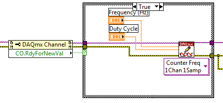
The error you get is expected in the way that you program your application. For another way to implement the property node and to avoid the error, please see the Developer Zone program example: output frequency of meter to change on the fly.
In this example, you will find this implementation:
I recommend you put it in your code and see if it is able to resolve the error you see.
In your program, as useless the DAQmx property and DAQmx writing during the definition of the duty cycle and frequency. You must just writing DAQmx to set these attributes.
Also, as a note, I noticed in your code that you never clear the task. Don't forget to end the application with a Task.vi claire DAQmx. I saw one in your program.
-
Calendar synchronized with Diuble pulse using PCI-6601
Hello
I'm trying to run a PIV of Labview 8.5.1 system using a PCI-6601 map at the exit of the signals for the laser and the camera.
This requires a line for the camera, one for the FPS (first removal of pulse) and one for the Q-switch.
The difficulty is in the need of a double pulse on the Q-switch for mode double frame PIV.
The distribution box that I use is not one NOR one and I don't have access to 3 outputs four against, otherwise, quite simply, I would use a BNC t with two pulses slightly staggered junction.
I have access to a BNC-2110 timing box, but I think it is not compatible with the PCI-6601 and have no funds to buy a BNC-2121 right now.
I managed to create a double pulse by using one of the counters with a finite number of impulses set to 2 and then stop the task, then run this in a timed loop.
However, it is then based on the software, which is not precise enough for the application, and I can't figure out how to get the timed loop to run from the time of 20 MHz of 6601 map base.
I could be missing something obvious here, or perhaps is more annoying? I'm fairly new to DAQmx.
Thanks in advance
Joe
Dominic makes a good point about the operating system, but really the best solution is to use the hardware timing when possible.
I have set up an example that shows how you can implement different sets of impulses finished using the calendar of the Commission. It requires the use of two meters, but then again a generation of impulses finished the fact (on the 6601).
Communities: Generate several Cycles pulse finished using two countersAlternatively, if you have another signal that you want to use to trigger each set of pulses (rather than to specify a rate so that they occur as in the example above), counters on a 6601 are redeclenchables then you can use the external signal to trigger the generation over time and time again without having to stop the task in the software.
Best regards
John
-
Using a counter with FiniteSamps and one with ContSamps
I am using 2 counters on the NI USB-6229 (or USB-6259), case where a counter is implemented for FiniteSamps and another for ContSamps. I have the following MeasurementStudio code:
ErrChk DAQmxCreateCOPulseChanTicks(hCnt0, "Dev1/ctr0", "", "20MHzTimebase", DAQmx_Val_Low, 0, 400, 400);
ErrChk DAQmxCfgImplicitTiming(hCnt0, DAQmx_Val_FiniteSamps, 100);ErrChk DAQmxStartTask (hCnt0);
ErrChk DAQmxCreateCOPulseChanTicks(hCnt1, "Dev1/ctr1", "", "20MHzTimebase", DAQmx_Val_Low, 0, 400, 400);
ErrChk DAQmxCfgImplicitTiming(hCnt1, DAQmx_Val_ContSamps, 2);
ErrChk DAQmxStartTask (hCnt1);
When I run it, I get an error-50103 "the resource specified is reserved". If I change the FiniteSamps to ContSamps on the first counter, everything works fine.
If I use only one counter with FiniteSamps, everything works very well.
Is this a bug in DAQmx or the use of double counter on M Series devices is limited to ContSamps?
VIC
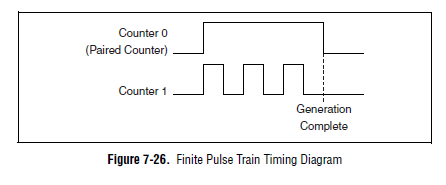
Hey Vic,
It is actually planned on a device of the M series. Here's a time diagram of the M Series user manual which might make this a little clearer:
The device uses actually one counter for the other door so the result is a generation of finite pulse. If you can provide the door from another source, you can configure a generation of continuous pulses on two counters and their door (DAQmx calls it a "relaxing break") of this external signal.
You can also look at the use of the digital I/o correlated to generate impulses over multiple (up to 32 lines on your 6229 and 6259). You could use one of the counters to generate a time base for digital lines and build the waveform as a result.
One thing to note is that our new X series cards can generate a generation of impulses finished on a "single" counter (it was actually a paired internal counter that allows this). There are four accessible counters by the user on the X series devices, which means you could generate four pulse trains finished.
Best regards
John
-
PXI-4461 generate voltage update
Hello
When you try to run the sample Daqmx VI "Gen - Update.vi of tension" with an NI PXI-4461, I get the following error:
200758 error:
"Type of sample Timing is set to on demand that is not supported for analog output on this unit"
What does that mean?
Is there another way to generate a constant DC signal with the 4461?
Also - for next time that consider us to buy a new card - where can I get information on DAQmx properties (like this one) are supported for each camera?
Thank you
Ran
Hi Ran,
The 4461 NOR supports HAVE no single-point / AO of because it is based on delta-sigma converters a/n/CED, which require a clock free run at a constant speed.
There are two ways to output a signal DC with an NI 4461 (or NI 4431):
- Continuously to generate a waveform to DC (containing several repeated values).
- Set channels DAQmx > AO. IdleOutputBehavior to "Maintain the existing value" can generate several updates.
The help of LabVIEW has a page of "properties of the NI PXI-4461 supported", but it does list all the supported values for each property for each device. NOR-DAQmx help has a page entitled "Considerations for DSA timing devices" that talks on this subject:
"
Considerations of timetable for DSA devices
Supported sampling frequencies
Unlike some other devices DAQmx, DSA devices have a maximum and a minimum sampling frequency. Check your device specifications determine the range of sampling frequency.
Other considerations of DSA calendar
DSA devices do not support the type of synchronization on demand. All acquisitions of DSA and generations require hardware timing of a stable clock.
DSA devices do not support external synchronization sources of arbitrary external signals such as tachometers and encoders. PFI lines on the DSA hardware can accept external clocks. You can program a DSA device to use an external clock only when it is a slave in several synchronized system device. Refer to synchronization of the DSA for more details.
"
Brad
-
Control correctly 3 heartbeats at 3 meters of material using PCI-6601
Hello
It is a sequel to a previous post
http://forums.NI.com/NI/board/message?board.ID=40&message.ID=7914#M7914
as for control a PIV of LabVIEW rig using a PCI-6601.
The task requires the production of pulses in three outings of the counter. The Q-switch laser, to a double pulse (which is resolved in the previous post), while the other two are simple impulses. It is important to be able to control with precision the difference in width and pulse between pulses.
As far as I understand, I need to configure timers to start and then run from the material without other software entry
I tried using the "initial deadline" option when creating counter channels, but it is very innaccurate (probably that uses the software?). Similarly, using the lag in call loops option does not produce a time delay (and requires the use of a meter as a synchronization source, leaving me without enough counters)
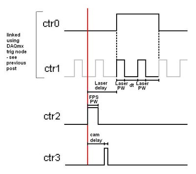
Below is a basic diagram time for a single iteration, keeping in mind that this must be repeated in the range of 100-1000 Hz, approximate pulse width (PW) would be 2 microseconds and delays in the region of 500 microseconds.
I need to be able to define
delay of Cam and laser delay with precision (and the pulse widths must be easy in theory)
Sorry if I forgot something important and thanks for your help
Kind regards
Joe
Hi again Joe,
We could just trigger all out 2 meter (pulse FPS which seems to start the acquisition as a whole).
CTR 2 would be a continuous pulse generation (at the rate we want to re - triggered the entire process).
CTR 3 would be a unique generation of impulses of retriggeralbe, with an initial delay.
CTR 0 and 1 are a bit difficult in the context of the rest of the application.
I think that the suggestion I posted in the previous thread should work fine by CTR 0 triggered with an initial delay.
Otherwise, we could do an output meter redeclenchables finished, but if I remember correctly there are specific behaviour with the initial delay of the finished products redeclenchables counter that could give us unexpected results (I would find the link but ni.com seems to be down at the moment).
I won't be back in the office until next week so I don't have any material to try this, but I think that should help you get started in the right direction at the moment. The desired behavior should be achievable, but it might take a programming smart everything for line lift correctly.
Using a trigger external or not should not affect the programming of the double line impulse which is the most difficult aspect of the application.
-John
Maybe you are looking for
-
We don't recognize your connection details
Hello I try to sign in to Skype with "microsoft account.But he said: "us does not recognize your connection details.I even reinstalled windows xp, but no result.It's used to work! But this week, it doesn't work anymore, what has changed? Thank you.
-
How to share files between Windows XP and Windows 7 without password?
Hey guys, I want to share files between windows 7 and windows XP. I don't want to put the password on my Windows 7 or Windows XP account. I am going on my Windows XP perfectly shared files from Windows 7, but I am not able to go on my files of window
-
original title: when trying to install fails KB2686509 open the faultykeyboard log and a list of the 20 folders from kbd. No idea what to do with them, please help. I tried to install the KB2686509 update and got an error on a sine qua non, who I am
-
450 proBook G1: upgrade i3 - 4000 m
Hello I want to improve my current processor, i3 - 4000 m, for an i7-4702mq. Is this possible? My motherboard is a HM87, 'model 1942, KBC Version 89,10' something BIOS L74 to. 01.07 other details - have integrated graphics Intel HD 4600, 4 GB of RAM
-
Where oh where can I start? When I start the computer, my office is always in the background, but there is a pop up looking for black box thing. There are no long enough for me to read what it says. Something about system/Windows32 (not full title