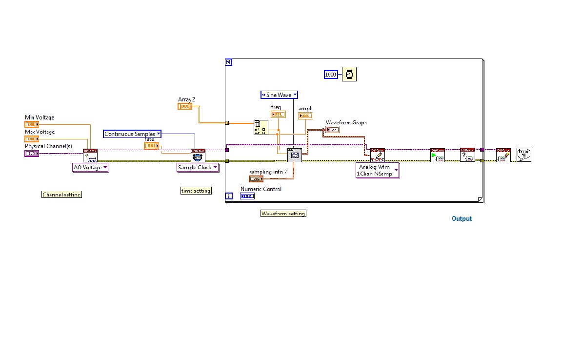
generation of signals using DAQMx.vi
I'm trying to generate signals with a generator block functional VI, with a lop fill and table with values of frequency and amplitiude
as in the diagram below.
When programs run at the end an error message pop up
- Error-200479 occurred at DAQmx start Task.vi
-Specified operation cannot be performed with task is running.
Tags: NI Software
Similar Questions
-
Generation of signals of segment
Hello!
How is it possible to generate such a signal (photo attached)?
https://pp.VK.me/c622024/v622024951/33e6f/I3zJNTMGiU0.jpg
A link to the answer (if there is one in this forum) would be great.
Thank you
This may work for a graph where it will automatically draw lines between points. But if it comes to the generation of signals, it won't look like that.
Look at the function of ramp model. Which allows to build the parts in signal Hill and initialize the array to build from scratch the parts and flat parts. Then use table build with CONCATENATE entries in order to combine these tables into one.
-
acquisition and generation of signals synchronized redpitaya impetus
Hi, I'm new in collaboration with redpitaya and labview.
I've been trying to get the example of the "generation of signals a synchronized pulse and acquisition" has worked with labview. But I have a few problems.
FISLY, when I downloaded it, some varibles where the wrong type, so connection could not be made (fig. 1). So I use a block converter (from string to number) in order to solve this problem, because he wan't work I changed directly two of the entries from string to number and I kept the conversion of the rest of the string variables (picture 2).
I was getting an error, but the example did not work properly. When I play run, it only resgisted noise, but not the signal that it was created (image 3). I changed the table (chanel I used, amplitude, frequency, the shape of the signal itself)
To check that the wire and the RF input and output was OK I tried to change the signal, put it on my hand and the change in signal to noise, but there was still noise (picture 4). I tried each entry and exit, but I still have the same signal: noise.
To conclude: I can't do this example to work.In addition, I have a question on this example, the labview and Redpitaya libraries: How can I change input 1 input 2 and from exit 1 to exit 2, because I don't see that option 1 of chanel and chanel 2, but it does not say what combination of input and output is. and I can't find the block to edit entries and exits
If anyone has had the same problem, how to solve it?
Thanks in advance!
Entries you 'fixed' are not numbers, looks like they are channel names. The representation has changed some time ago, but it is an example of the former.
Mike...
-
Output signals controllable DAQmx (real-time)
Hello:
I have a question here.
It is quite difficult for me, and I can't find any bad example and discussion.
Hope that some people give me some information for me to look it up.
--
I am trying to generate an analogue signal into a DAQmx device (I have an and uses it well) to control another device.
The output signal must be the sum of a background signal (which is decided, let's say a sine wave) and another control signal.
The control signal depends on the entrance of real-time control, for example by using the horizontal location of the mouse to the value of the signal.
The background signal is designed in advance and it will run continuously (should not be stopped once the system starts to ensure that synchronization between each devices).
At the same time, the control signal should be continuous. (if there is no new entry, it uses the default value or the last entry).
--
I have almost no idea on how to do it.
As far as I know, needs only one daq task to write the signal, and then she runs after.
The control signal is a thing in real time, so the task needs to be updated very quickly.
But regeneration tasks cost 50ms ~ on my computer (and I used the low levels rather than the DAQ assistant Renault).
Also, in this case, my background/control signal will be be stopped every time that when the task is regenerated (and this makes my synchronization failure.)
I checked DAQmx in real time, but couldn't find a few examples of tris and seems it isn't for my application actually (?).
A possible solution, I came is cascading my two signals once they are generated by my DAQ hardware. And then I can use an a/o to be the background signal and use an another a/o to be the control signal.
However, my control signal is always interrupted between each loop, and the method of external cascade seems not smart.
Or data acquisition is not perhaps suitable for this application?
--
Hope that some people give me some information and then I can check their.
Thank you very much
Hi Jhensi,
How the example provided was for you?
With respect to the delay that you experience, there is always a slight delay incurred as a result of underlying driver DAQmx running in the background.
In addition, your USB 6611 will have inherent delay due to being used as the communication protocol USB bus. There may be up to 100ms latency in some cases with USB 2.0.
This driver requires a certain amount of time to change the type of output signal, that is production.
A user will never really feel a 'Real-time' experience when you use an application that uses DAQmx. Deterministic control applications almost always use an FPGA with a real-time embedded controller.
It is possible that other delays are due to timing considerations in your code but if you checked these it may be a hardware limitation.
If you could let me know how you do that would be great.
Kind regards
-
I need the raw ADC output card PCI-4462 using DAQmx
I need the raw ADC output card PCI-4462 using DAQmx
Is it possible or are only regulated units availible.
Ken Manatt
There is a version of 'Raw' DAQmx Read (see image). This is probably what you are looking for.
-Alan

-
How can I use the USRP to record a signal using its two RX ports simultaneously?
Hello.
I am trying to record a signal using two antenna cone. The reason that I need two antenna to cover the bandwidth (DC - 6 GHz). a single antenna covers DC - 300 MHz and the other covers 300 MHz to 6 GHz. so I need to use two RX port of USRP at the same time to record the signal. I have two questions:
1. is this all USRP market capable of covering this frequency range?
2. is it possible to use the two RX port at the same time to the signals of the records I described? If this is not the case, how can do?
P.S. I have two NI2920 USRPs and two USRPs N210 in my lab.
Thanks in advance for your time.
Sam.
Hi Sam,
To answer your first question, the USRPs you can reach the bandwidth you want. There is not a USRP, to my knowledge, that can reach this range in a single device.
Also note that you can only use RX convened for two different ports at the same time using LabVIEW and the pilot of the USRP. If you want to use the two lines of RX, you will need to run a session with a single line, close the session and then start a different session for your second RX line.
-
How can I pause and resume the analog output using DAQmx?
I use a DAQ hardware to produce an analog waveform. I would like simply to break the output of the wave and then resume where it left off. I use DAQmx and LabVIEW 2011.
I've seen examples that use a digital or analog break trigger, but I would take a break in the software only. How can I do this?
-Joe
Hi Joe!
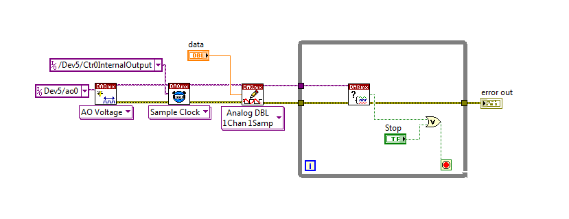
I spent some time thinking about it and I realized that you can technically use a fundamental mission of the analog output, as you previously wrote that runs continuously. However, the generated output samples are controlled by the sample clock pulses, and can be manipulated to fit our needs "suspension."
To do this, we will need another counter task that generates a pulse train (see our examples of shipping under material input and output > DAQmx > generating digital pulses > generate dig Pulse Train - Continuous.vi) that stops and starts the user to choose. This can be in another quite VI or controlled by software. We will use this as the task of our output sample clock.
Then, the task of the AO, wire a constant to the sample clock source and select ' DevX/CtrXInternalOutput"based on the counter that you specified in the task of counter. You will need to choose "I/o name of filtration" and check the box that says "include advanced terminals' and right-click of the constant. See picture attached as a reference. In this way, the task of the AO is constantly running, but it generates only actually all data when the meter running task.
Let me know if you have any questions!
Have a great day!
-
Generation of signal Pulse width modulation for ULx
Hello
I'm trying to produce an analog waveform (IE square wave) with an option to control the cycle.
I went out with a Measurement Computing card, which uses the libraries of user ULx.
There are many examples of do what I want to use DAQmx, but all those who use ULx have no option to control the duty cycle.
Can anyone help?
Thanks in advance.
Hi ben,
your hardware ULx even does support the PWM outputs? Support the tasks out of meter?
It is not only the software, the material must also support your needs!
-
How self test 6713 using DAQmx programmatically?
I use DAQmx and I need to be able to perform a self-test on a map of NI 6713 analog output without using MAX. Any suggestions?
DevtPro,
As you can see in this document , the recommendation was to use Reset running as self-test in addition to other things. Currently in DAQmx 8.9 and later there is a Self - Test.vi DAQmx that allows to run just a self-test. I already submitted a change to this document and it should be reproduced soon.
-
Reading of analog signal using DAQPad-6016
I'm reading an analog signal using DAQPad-6016. An entry is on the ground, the other is Vdc. I can't operate at MAX and I'm confused becaue MAX alone gives me an option for differential reading, but the list of pins give enough information on how to connect in a different way. Is there a reference as well?
Hello, Bernadette.
This link should have what it takes to equip themselves properly: http://www.ni.com/gettingstarted/setuphardware/dataacquisition/analogvoltage.htm
After that you have put work in place, specifically see step 11 for check the connections of the device.
I hope this helps!
-
How the ND_SCANCLK_LINE signal used in DAQmx? It is complete Hold event?
I have moved an old application (using the PCI-6013-OR map) to DAQmx recently, but have some difficulty working. When starting, the signals are configured as shown below.
Select_Signal (1, ND_PFI_2, ND_IN_CONVERT, ND_HIGH_TO_LOW);
Select_Signal (1, ND_SCANCLK_LINE, ND_SCANCLK, ND_LOW_TO_HIGH);I've done the migration as shown below.
Select_Signal (1, ND_PFI_2, ND_IN_CONVERT, ND_HIGH_TO_LOW);
DAQmxExportSignal (TaskHandle, DAQmx_Val_AIConvertClock, "/ Dev1/PFI2");
DAQmxSetAIConvActiveEdge (TaskHandle, DAQmx_Val_Falling);Select_Signal (1, ND_SCANCLK_LINE, ND_SCANCLK, ND_LOW_TO_HIGH);
DAQmxExportSignal (TaskHandle, DAQmx_Val_AIHoldCmpltEvent, "/ Dev1/AIHoldComplete");
DAQmxSetExportedAIHoldCmpltEventPulsePolarity (TaskHandle, DAQmx_Val_ActiveHigh);But my application displays the data in the form of two samples shifted left. I guess that the acquisition has been delayed.
I do correct migration or is there something different in the DAQmx?Documentation OR that I get confused whether ND_SCANCLK_LINE or AIHoldCmpltEvent sample clock. Or is this sample clock?
What is the SCANCLK Signal, and how to use it?
Hope this helps
-
Photon counting using the FPGA of the series R. problem generation TTL signals
Greetings,
I try to use the R series FPGA to read and count the pulses TTL of a discriminator (count of photons of the Hamamatsu C9744 unit) connected to a PMT (Hamamatsu-H7422P-40). The release of PMT looks fine (signal.png H7422P-40) but the discriminator wasn't able to generate corresponding TTL 5V pulse. There was some scattered and random spikes, but nothing significant. Instead, the only stable the PMT signal is a single + 5V pulse no matter how, I adjusted the PMT (C9744 output.png) control voltage. The PMT and the discriminator is connected by an ordinary BNC cable 50 ohms.
I am really confused because it was supposed to be a really simple installation. Anyone have a similar question or have similar Instrumentation (but no problem) configuration? Comments/suggestions are greatly appreciated.
Thank you very much in advance!
Hi Kelli,
Thanks for your help. Sorry it took so long to get back to you.
I actually found the question. The discrimination of the Hamamatsu unit level is set too high that all signals got filtered. After adjustment of the threshold of manuallyt, I was able to get the camera TTL pulses. And 7842R worked correctly for count impulses. Everything works fine now. Thanks again for the input.
-
generation of two complementary pwm signals using myrio
Hello, im working on a project and I need to generate two complementary pwm signals (when we go to 1, the other goes to 0) using myrio.
the problem with the blocks of myrio pwm is that when you set the market factor, the signal always starts with its high value. Can someone help me please?
Hello
You can create a Boolean square signal with chosen service and frequency cycle, create its opposite with makes NO sense and then send both signals via Digital Out vi (myRIO/Default/Digital Out) to two different outputs.
Best regards
-
Counter the acquisition and generation of simultaneous signals of Daqmx triggered
I am writing a vi that collects the data of a specific length (1000 points) when writing the data of the same length on another port on the same card (PCI-6052e). Collection and production are both triggered by a pulse of a counter on another Board (PCI-6711). I am able to trigger both successfully, but not at the same rates and not to the desired resolution. The generation of waves and the collection forms should be 8 msec in duration. I have attached the screws. Any ideas would be appreciated.
Thank you
Jordan
Eventually clocked continuous generation, but the displacement of the wave write vi DAQmx out of the loop (just before the beginning of vi), and this fixed the calendar.
-
niHSDIO dynamic generation and Acquisition using LV configure Trigger VI
Hello!
My experience is limited within the environment of digital programming; Nevertheless, I have worked on this problem for a few days and would appreciate some comments if possible.
I am trying simply to generate and acquire a duty cycle of 50% of 8 MHz TTL pulse train on a PIN DIO of the PCI-6541 and acquire back from the signal on another axis of DIO. I have a connector corresponding to the embedded 6541 VHDCI connector which of course the generation and acquisition DIO welded pins to provide a loopback effect.
In short, I use the niHSDIO configure Trigger VI (instance--> start Trig: SW), niHSDIO send software Edge Trigger VI and write Named Waveform VI (instance--> data: 1 D U32) in the generation section. For the section of the acquisition, in short, I use the VI of waveform Fetch niHSDIO (instance--> single record: WDT).
I see results in the waveform acquired showing the generated and acquired digital TTL pulse on the respective DIO pins train, but I can't seem to get my 8 MHz frequency requirement. In addition, the lower part of the assignment of pin DIO, more frequency. Unfortunately, due to the configuration system required, I have confined myself to pin 12 DIO for the generation of digital pulses. Even with a 50 MHz clock frequency, I'm ~ 6 kHz of frequency acquired max. I looked at changing the parameters of the wave form VI named write, but it is not possible because the VI call a library function node. I also tried to generate a waveform of 8 MHz through a VI of generator of digital model, but I do not believe, you can trigger on generated waveforms? It seems that you must generate data using a simple loop to as a counter and sending the result to the waveform VI named write. Are there other ways I can simply generate and acquire a digital signal of TTL of 8 MHz (no external connection)?
In any case, any kind of feedback would be greatly appreciated.
Thanks in advance for your time.
Dan
Dan,
Sorry about the nomenclature. I usually use 0 x or 0 b for indication of radix, it is not necessarily a kind of standard, just what I used in my old days of the Assembly.
Looks like you have a knowledge about the data. Basically the material is just save in DRAM an array of words of 32 bits, with each bit corresponds to a data channel and each element being generated to the sampling clock rate you enter to your vi. Everything else is just easy data manipulation or usage. The interleaving method is just as I like to create a toggle model. You can easily do a loop with an inverter and feedback node or use on the construction in screws to signal generation. In addition, you can use the software digital waveform editor or control panel test to generate the county or toggle modes.
Give us an update when you enter the laboratory and let us know if you encounter any other disorder.
Maybe you are looking for
-
Should there be two active instances of Adobe Flash player when using Firefox for windows?
Firefox (35.0.1) used my resources to i7 CPU like crazy lately, slow down the loading of the page, scroll, etc. I am running windows 8.1. When I went to Task Manager to see what was causing the slowdown, Firefox took 44.8% of my CPU, and I noticed th
-
New PC synchronization, import is not previous PC settings
Just install windows 7 new PC. Previously introduced synch on the old Windows XP machine. New PC on signature resynchronize only importing is not all bookmarks etc.
-
I have a hp pavilion p2-1105, and every time I press the button to eject my disc tray opens. What can I do?
-
I've forgotten the answer to my security questions.
I've forgotten the answer to my security questions. How to reset?
-
cRIO: error when compiling an application in real time
My code can be executed when the cRIO is connected to the PC with Ethernet cable. But when I want to compile my code (Release), I get the following massage. Also the image of the massage is shown below. //////////////////////////////////// Visit ni.c