Generate a ramp single signal
I can't understand the time settings of the simulate arbitrary signals.
I want to make a single ramp of sur.990ms-1 to 1, then return-1 in slot 10. So, when I put a loop for, I can get in saw teeth N cycles.
I've been pulling my hair out trying different options of the dialog set signal and cannot get there.
Can someone help me understand the relationship of dx to the datapoints and how they are affected by the numbers of the writing/sample in data acquisition? Please, I beg you.
Christopher
This should help you get started. You will need to put in place the analog output in the software to match your system. If you change the frequency and the number of sample and loop of delay so you can do go faster and more slow a lot easier.
Tags: NI Software
Similar Questions
-
How to generate a continuous ttl signal with a USB-6501
Hello everyone,
I am a beginner with LabView, so maybe my problem, it's very easy to fix.
I need to generate a digital output using a USB-6501. This TTL signal will then switch to a device. Basically, I need the digital output to be permanently to TTL high level until a user active departure is given. Then the digital output must stay to the TTL low level until another stop active user is given.
Does anyone have any suggestions on how to do? I have failed so far to get something different high TTL to my USB 6501.
Thank you very much.
Hi there, take a look at the VI I enclose. You can find more information about the device in textbooks and on this forum. I hope this helps
-
How to generate two different analog signals in two different screws
I use a card PCIe-6321 and a block of connection SCB-68. As it has two analog outputs, I use one of these outputs in a Vi to generate a square wave, and the other in an another VI to generate a sinusoidal output waveform. Each VI perfectly work separately, but if I run one then the other, the other sends no signal. Because I don't want to merge the two screws (it is more convenient to use them separately), how can I find out so that they work together (sometimes).
Of course, independent maps with timing motors, controlled by the works of independent screws.
Christian
-
generate the ramp of the order of the layers
Is there a method (effect or script) that will apply a linear ramp to layers based on where they sit in the comp? For example... If it is a composition of 100 layers, layer 1 would turn white and 100 layer would be black. Any help or advice would be greatly appreciated... trying to figure out a quick solution to generate a picture of ramp based on the order of the layers.
Thank you!
Siri and my iPhone help me with this answer.
You can apply the hue and saturation of your layer. You can then add an expression to the brightness value. The expression is very simple. It only requires that you know how many layers to use.
If you have 100 layers and a composition of eight bits and then each layer must be reduced in luminance of 255÷100. Expressions include the number of layer by using the index of the expression.
The expression looks like this:
(index - 1) * 25.5;
Now just duplicate your layer 100 times.
The top will have a luminance you 04 Black, the background will have a luminance value of 255.
I'll doublecheck this when I get to a computer, but I think it's perfect.
-
Why it is so hard to generate the Master square signal?
Hi, I just can't do this work.
I want just a square of 1 Hz through Dac1 output
and receive it by cable to ach0.
Can't make it work...
Of course, this does not. You do not have to understnd dataflow. The top loop will not start until the low finishes and when the bottom ends, it immediately stops the upper loop. Remove the dependency of data between the two loops (i.e. don't wire from one to the other).
-
How to allow multiple users to view alerts generated by a single user
Hello
I created some alerts in the log Insight 3.0 and I want my colleagues to be able to see and modify. Is this possible? If so, how can I do it?
Thank you.
Shared alerts do not exist today. The workaround is to create a shared user that several people can connect to. For more information, see: 3 reasons to use a Service account in the journal Insight - SFlanders.net
-
Generating signals simultaneously on two channels (SMU-5451)
Hello!
I'm trying to generate 2 different signals on the two output port of my SMU-5451.
Signals transmitted from data read from the file of PDM.
I'm able to generate 1 1 channel signal. But I can't ' figure out how to complete the data for my 2 channels memory and let generator simultaneously press these data or their respective!
Can any help? Maybe an example?
Thank you!
Hello Mr. Gambini,.
You can find all the information to do this here:
http://zone.NI.com/reference/en-XX/help/370524P-01/siggenhelp/5451_ni_5450_multichannel_allocation/
Particularly:
"To write waveform data to two channels at once, you must first striping of the data. "Once the data are interleaved, call the VI niFgen write Waveform (poly) or one of the wave functions write niFgen with the channel parameter set to"0.1"
Kind regards
-
PXI-6602 generate signals in squaring A, B with DAQmx in CVI
Hello
I want to know if it is possible to generate a quadrature encoder signals...
I want to generate the Signal A, then B Signal with a 90 ° of the delay on the other and be able to set the number of pulses that I want to generate.
I tried to generate signals with DAQmxCreateCOPulseChanFreq, but I can't start Singal B with the delay of 90 °.
Have any experience on this?
Thank you for your help,
Hello gramirezv Hello,.
Here is a KB which may help you to generate two trains of pulses with the same frequency but with a phase shift:
How can I generate two pulse Trains phases shifted from each other on my E series card?
http://digital.NI.com/public.nsf/allkb/26CCE4F74DACFD1886256DCF006B011A?OpenDocument
Have a lovely evening,
Best regards
CaEnOs
-
Generated sending the signals to a remote computer in a network
Hi guys, I am new to Labview and need help. I use Labview to generate a voice modulated signal and I want to send this signal to a remote computer (real-time). How can I do this, so that this voice signal is regenerated in the remote computer?
Hi Sarah, thanks for the advice.
-
Output a TTL HIGH 10 usec via the PFI port on AWG signal generator
LV dear community,
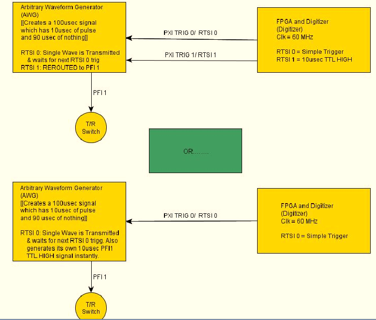
I want my signal generator (PXI-5422) to produce a pulse of 10usec with its PFI1 range each time that a wave of exit CH0. The frequency of repetition of the CH0 impulses and the port of PFI1 is 10 kHz. Is it possible for the signal generator automatically generate this HIGH TTL signals for usec 10 on the PFI1 line all at the same time produce a long-wave 100 usec?
Another approach, that I'm considering is to re - route a pulse of RTSI1 (10usec) from an FPGA and output via port PFF1 of the GTS. However, I doubt that this is possible, as the HELP MENU for the working group said that the report can only occur when the Working Group is in "idle" mode.
Any help will be greatly appreciated!
Have a nice day
 I have attached a diagram of operation that hopefully, explains what I'm trying to do a little better. Once again thanks for looking!
-Daniel
Hi Denn_Mann,
To get around the limit of 320ns, you should be able to use scripts with the FGEN markers to achieve your goal. Anything you want to do is use of script with markers in alternating mode. You may want to toggle high then low rocker after the number of samples you want pulse is high while your signal is present. I've linked some information below that should be good resources for script for you if you are not familiar.
Trigger on the arbitrary signal generators and advanced waveform sequencing
Creating an event marker in Script Mode
Script mode
Example of the expedition: "Fgen Arb Script.vi.
Kind regards
Ann Travis
-
How to build a parser of vector signals PXI using different module combinations
Normal
021
fake
fake
fakePT - BR
X NONE
X NONEMicrosoftInternetExplorer4
/ * Style definitions * /.
table. MsoNormalTable
{mso-style-name: "Table normal";}
MSO-knew-rowband-size: 0;
MSO-knew-colband-size: 0;
MSO-style - noshow:yes;
MSO-style-priority: 99;
MSO-style - qformat:yes;
"mso-style-parent:" ";" "
MSO-padding-alt: 0 cm 0 cm 5.4pt 5.4pt;
MSO-para-margin-top: 0 cm;
MSO-para-margin-right: 0 cm;
MSO-para-margin-bottom: 10.0pt;
MSO-para-margin-left: 0 cm;
line-height: 115%;
MSO-pagination: widow-orphan;
font-size: 11.0pt;
font family: 'Calibri', 'sans-serif ';
MSO-ascii-font-family: Calibri;
MSO-ascii-theme-make: minor-latin;
MSO-hansi-font-family: Calibri;
MSO-hansi-theme-make: minor-latin;
mso-fareast-language: EN-US ;}Normal
021
fake
fake
fakePT - BR
X NONE
X NONEMicrosoftInternetExplorer4
/ * Style definitions * /.
table. MsoNormalTable
{mso-style-name: "Table normal";}
MSO-knew-rowband-size: 0;
MSO-knew-colband-size: 0;
MSO-style - noshow:yes;
MSO-style-priority: 99;
MSO-style - qformat:yes;
"mso-style-parent:" ";" "
MSO-padding-alt: 0 cm 0 cm 5.4pt 5.4pt;
MSO-para-margin-top: 0 cm;
MSO-para-margin-right: 0 cm;
MSO-para-margin-bottom: 10.0pt;
MSO-para-margin-left: 0 cm;
line-height: 115%;
MSO-pagination: widow-orphan;
font-size: 11.0pt;
font family: 'Calibri', 'sans-serif ';
MSO-ascii-font-family: Calibri;
MSO-ascii-theme-make: minor-latin;
MSO-hansi-font-family: Calibri;
MSO-hansi-theme-make: minor-latin;
mso-fareast-language: EN-US ;}I understand
Vector signal analyzers OR consist of 2 or 3 separate PXI modules: 1
digitizer, 1 buck converter of RF frequencies and 1 generator of signals (model 5663).1. can I use digitizer and signal
generator general purpose oscilloscope and generator of signals separately?2 may I build my own VSA by choosing
different combinations of scanners and the signal generators? Or replace the signal
generator by an arbitrary signal generator?3. I
intend to buy a digitizer/oscilloscope and an arbitrary signal generator
analysis of response of frequency on the transformers. Later I plan to
buy a step-down converter frequency and build a vector signal Analyzer. Is this possible?Hello
The frequency IF the 5660 and 5661 (it's the same thing) is 15 MHz, with an instantaneous bandwidth of 20 MHz. The difference between the 5660 and the 5661 is located in the digitizer that accompanies it. The 5660 uses the PXI-5620 digitizer that has a sampling rate 64 MECH. / s and a buck converter of digital frequency limited to 1.25 MHz of bandwidth. The 5661 uses the digitizer PXI-5142, giving you a MECH 100. / s rate and a PSO allowing digital downconversion circuit and the decimation of the full bandwidth of 20 MHz.
The common comment in the SBA above is the RF PXI-5600 frequency step-down converter which is a superheterodyne architecture of three floors. OL is for the three stages of this module are auto-approvisionnées in their own country. The architecture of several step allows for rejection of the improved image and filtering at the expensive of a noise floor slightly higher due to the signal path more complex. There also an OCXO on board, this gives him a time reference more precise - noise reduction phase etc. The PXI-5600 by itself is wide from three locations.
The SMU-5601 since SMU-5663 step-down is designed based on the single frequency step-down converter and resumes from a single location. The celled frequency step-down converter gives you improved noise floor characteristics and a better dynamic range, with the rejection of the image fees, having does not simply because there is only one step. The LO is provided by an external module in this case for several reasons. Have a separate external LO allows more modularity in your system, as well as the ability to share a single LO generator between several vendor-specific attributes. This opens the possibility of MIMO applications. The internal of the NI PXI-5600 LOs are not shareable and therefore cannot be synchronized between several PXI-5600 s. The PXI-5663 (all three modules) takes up the same amount of space in the slot as a single NI PXI-5600 without a digitizer.
The PXI-5154 is indeed a powerful scanner, given its instantaneous bandwidth of 1 GHz. Remember, however, that the connector Active Directory on this digitizer is 8 bits, compared to the 5622 which is 16-bit. If you need more resolution is of course entirely depends on your application. The PXI-5600, as SMU-5601 is controllable as a buck converter stand-alone frequency using the DAMA API OR. You will need to program your application with the scope API for use with PXI-5154 OR and the API de DAMA. A few other caveats to note is that there is no PSO on the PXI-5154 so you can't enjoy the Equalization filter to correct the frequency of the NI PXI-5600 response. Also, as I mentioned above, the frequency of YEW of the NI PXI-5600 has 15 MHz with a bandwidth of 20 MHz - processor 1 GHz bandwidth on your digitizer will be somewhat of an overdose of the IF signal.
While you're dead on with the advantage of modularity, I would take the time to really meet your search application and ensure that different choices of module and their combinations to meet these needs.
Hope that helps!
-
Hi all
6341 USB only generates a 5V DC signal. It works of NI USB-6009, but not of 6341. IM choosing AO, 0, 1 sample (on request) and feed a constant 5 integer to him. With the help of pins 15 and 16 (AO0 and AO 0 GND)
Using Labview 2013 and DAQmx 9.7.5
Help please!
Have you tried to use the test panel in MAX? It is a good starting point. The other thing is to try other analog output channels to see if none of them work.
It could also be that your 6341 does not keep the value that you are out once the program ends. You have just a DAQ support to write a single point, then your program ends. Try to test the panels in MAX and see if you can monitor the AO line like that.
You can also try an example of shipping from the example Finder (help > find examples). I recommend watching analog voltage - on application exit.
-
I am actully trying to create a time delay in a signal and then later I want to apply an algorithm to find TDOA between signals from a single signal source. They have a relative phase shift and tried to model a VI so that I can see the signals visually and analyze TDOA analytically first, and then ensuring the proper functioning of the Algo.Currently I am unable to differentiate visually signals having different phase on the only indicator. I see that a single waveform. I want to see both...
Hi defined
Right-click your plot of annexed table and go to the tab 'Balance '. At the bottom of the "Balance" tab, make sure the 'ignore wave timestamp x - axis' is not checked. The parameter t0 on function 'Building the waveform' is a timestamp data type. If this box «ignore...» "is checked, the chart uses the indices of values Y, which always start at zero.
Note that the generated waveform will have a number of samples and that change the original horodotage moving all samples.
Let me know if you have any other questions!
-
Hello
I'm totally new to LabView using Labview 8.6.
I have a PXI-6704 and on three channels, I should generate a ramp between 0V and 840 mV less than 1 ms, then the signal must remain constantly at the 840 mV. This signal will begin some on-chip oscillators.
I checked the other kind of similar examples as well, but as it's my first experience in LabView I really understand many of them.
Please can someone help I have to use to get the EXPECTED signal? Or if someone has a vi to do this...
Thank you
Kriváň
Help > examples > entry & exit hardware > DAQmx.
-
PXI-4461 generate voltage update
Hello
When you try to run the sample Daqmx VI "Gen - Update.vi of tension" with an NI PXI-4461, I get the following error:
200758 error:
"Type of sample Timing is set to on demand that is not supported for analog output on this unit"
What does that mean?
Is there another way to generate a constant DC signal with the 4461?
Also - for next time that consider us to buy a new card - where can I get information on DAQmx properties (like this one) are supported for each camera?
Thank you
Ran
Hi Ran,
The 4461 NOR supports HAVE no single-point / AO of because it is based on delta-sigma converters a/n/CED, which require a clock free run at a constant speed.
There are two ways to output a signal DC with an NI 4461 (or NI 4431):
- Continuously to generate a waveform to DC (containing several repeated values).
- Set channels DAQmx > AO. IdleOutputBehavior to "Maintain the existing value" can generate several updates.
The help of LabVIEW has a page of "properties of the NI PXI-4461 supported", but it does list all the supported values for each property for each device. NOR-DAQmx help has a page entitled "Considerations for DSA timing devices" that talks on this subject:
"
Considerations of timetable for DSA devices
Supported sampling frequencies
Unlike some other devices DAQmx, DSA devices have a maximum and a minimum sampling frequency. Check your device specifications determine the range of sampling frequency.
Other considerations of DSA calendar
DSA devices do not support the type of synchronization on demand. All acquisitions of DSA and generations require hardware timing of a stable clock.
DSA devices do not support external synchronization sources of arbitrary external signals such as tachometers and encoders. PFI lines on the DSA hardware can accept external clocks. You can program a DSA device to use an external clock only when it is a slave in several synchronized system device. Refer to synchronization of the DSA for more details.
"
Brad
Maybe you are looking for
-
Just upgraded to FF 12 FF 3.6 and most of my favicons are now places dotted. Is it possible to get favicons associated with each web site to load? I've seen some suggested code to add, but I'm not savvy web code. Thank you!
-
Rocket will not appear on Win7, Fuze + screen goes black
Sansa Fuze + with Firmware 2.38.06A on Win7 I use an Amazon Kindle cable to connect my Sansa Fuze + Win7. Because I forgot the cable supplied with the rocket. They are two data cables so that both should work. When I turn on my Fuze +, it turns on no
-
My grandson has tried to install a Microsoft LifeCam our Vista Home Premium system 5000.on... He did something in the area of administrative privileges... this software will be neither uninstall (error file security: c\Program\Files\MicrosoftLifeCam\
-
Get an IRQL error when reinstalling Vista on a formatted HARD drive.
My (HP a1700n) office has been very slow, perhaps a virus. I ran Norton NIS and also had Norton disk utilities cleaner. Before that the Office stopped completely, I was able to shoot the important things (pictures, videos, etc) nothing else I could l
-
IOS VPN will not respond to connections Cisco VPN Client.
Hi all I'll put my routers fire here. I have two 2921 SRI both with licenses of security concerning leased lines separated. I configured one to accept our workers to remote Client VPN Cisco VPN connections. I have followed the set up process I used o