signal CC 6341
Hi all
6341 USB only generates a 5V DC signal. It works of NI USB-6009, but not of 6341. IM choosing AO, 0, 1 sample (on request) and feed a constant 5 integer to him. With the help of pins 15 and 16 (AO0 and AO 0 GND)
Using Labview 2013 and DAQmx 9.7.5
Help please!
Have you tried to use the test panel in MAX? It is a good starting point. The other thing is to try other analog output channels to see if none of them work.
It could also be that your 6341 does not keep the value that you are out once the program ends. You have just a DAQ support to write a single point, then your program ends. Try to test the panels in MAX and see if you can monitor the AO line like that.
You can also try an example of shipping from the example Finder (help > find examples). I recommend watching analog voltage - on application exit.
Tags: NI Hardware
Similar Questions
-
Amnesty International and counter sync + USB signal stream (USB-6210 vs USB-6341)
Hi all
I'm at a stage of identification of a material suitable for the following tasks:
- 5 analog inputs (AIs) of reading at the same time, tensions at a rate of kSps (at least) 10,
- application captures 2 inputs using timers (detection of contours with timestamps), square wave entry with duty ratio of 50 percent and about 1.5 kHz frequency and variable pulse width / frequency (from 2 sensors hall, representative of the DC motor rotation speed and direction, quadrature signals), resolution of timestamps should be (at least) 50 ns,
- AIs and counters should behave in a deterministic way, and must be synchronized in a way,
- data to be transferred via the USB port of a host computer with Matlab Data Acquisition Toolbox (unfortunately not LabVIEW).
I've identified the long USB-6210 USB-6341 and potential candidates of material to accomplish the above tasks, but after reviewing several documentation and the topics of the forum, I'm still a bit confused, if both are fully working and my approach described below is not working properly.
Counters: I intend to use the internal time base available 20 MHz as being the source of meter to get into account the resolution of timestamp 50 ns. External impulses hall are used as sample clock (about 1.5 kHz, see above). As the pulse width varies, the sample clock is not constant.
AIs: Using a 10 kHz internal clock signal derived from the time base of 20 MHz for timing and analog inputs (trigger) start-up and counters simultaneously material should translate into the required synchronization and deterministic behavior.
It work? Other recommendations?
Next is the USB data transfer: all HAVE 5 and 2 data entry of the meter must be correctly transferred to the host computer (the corresponding rates are shown above). USB-6210 is capable of 4 USB signal flow, device USB X range (6341) offers 8 of them. Unfortunately, I could not understand the exact meaning of the expression "signal flow" still. Do I need 1 flow of input signals (would be 7 for my application described) or 1 stream for all analog inputs and 1 for counter inputs (lead 2 streams for my request). Is there no further details on this approach (more than Streaming of signals of NOR) USB signal flow?
Any challenge to the described application that I might have forgotten? 6210 USB seems to a very limited number of entry PFI, maybe even too low for my meter participate application?
Looking forward to your comments and advice.
Concerning
jAwA
1. I recommend the X-6341 series on the M-series 6210 sake of counters/timers. It is more of them, and each of them is more capable. It can also have a great FIFO embarked for meters that may be important in certain tasks, although I don't think that you currently deal with one of them.
2. your general concepts on timing & sync are satisfactory. You will be able to share and to route signals that help ensure synchronization and determinism between the timestamps for your various tasks. Note that for meter entry tasks, you need set up the trigger 'Arm Start' rather than the regular start trigger.
3 is not authoritarian, but I believe that the flow of signal # will correspond to the tasks #. For you, it would be 1 task of HAVE and tasks CI 1 or 2. (Not clear if you have 1 Encoder with 2-channel quad that would require 1 task of CI, or if you have 2 encoders with 4-way quad).
4. pay attention to the hall effect signals that are not virgins. Digital filtering is available and probably better on the X-series, the series M.
5. strictly speaking, edge detection is a type of digital input task that produces samples but no timestamps. Ideally, I would like to parallel wires on the two digital inputs for the entries of detection and counter change to position quadrature decoding. Then I would sample the counters Encoder 1 or 2 using the internal pulse 'event of detection of change '. I would create another counter timestamp change detects pulses as well.
-Kevin P
-
connect multiple signals card NI USB-6341
Hallo,
I'm trying to connect the signals of several NI USB-6341 map.
This map has 16 channels but not 32 pins available.
for example if I want to connect a signal on channel 0 I connect to pins 1 and 2 and for channel 8, I have to connect to channels 2 and 3.
If I connect only channels 0-7, it works but if I connect channel 8 I do not get the real value of this signal.
any ideas?
Thank you
Theodore
Theodore,
This sounds like it should work. Basically, you use AI0-3 and AI8 - 11 for your four differential signals. This leaves you AI4 - 7 and AI12-15 free for single operation is complete. The configuration of the terminal can be defined on each channel. To do this, you can use DAQmx create channel several times to add channels with a different configuration to your task. If you need details on it, let me know what environment you'll be programming, and I'll see if I can provide more specific assistance.
Hope that helps,
Dan
-
I am currently trying to catch once a rev signal in the form of a square wave of 5 v, using an acquisition of data USB-6341. I have it configured as an analog voltage currently and am able to look at the level of voltage coming out. My first attempt was to take the output voltage and compared to a threshold and trigger an event from that, but I could never catch a value on the threshold. How can I trigger on a rising edge for this type of signal?
Thanks for the details, which helps a lot. I thought the camera was a configurable delay - more modern do machine vision cameras.
So, essentially, you want to trigger the camera to capture a picture whenever the time by rev signal is considered only if another condition (such as data acquisition channel exceeds the threshold) is also true at this time?
The inconsistency, you are referring is almost certainly caused by jitter of the synchronization of the acquisition software. You will get a lot more deterministic performance using a periodic trigger of material for the camera, then throw the images you don't need. The only real downside to this is that time CPU extra absorbent false images, which should be minimal. If you want a pure solution of HW, perhaps use an external Boolean AND door to ensure the time by rev signal only go through if another signal (defined by the DAQ card whenever the other condition) is high.
-
Audio measurement with the USB NI 6341
Hi, I tried to find a forum, but has not found an answer to my topic.
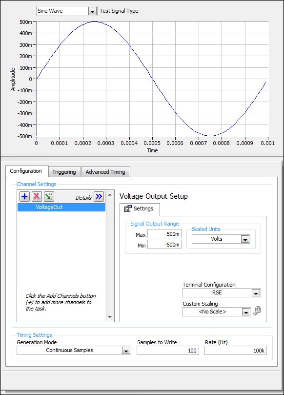
I have an usb-6341 or data acquisition. in our project, I want to generate 1 kHz sine waves go AO0 and inject our test module and the output
I want to measure the output signal of AI1.
in the NI MAX tasks Panel, I made this settings
If I understand correctly to produce the output signal of 1 kHz I put samples to write = 100 and a frequency of 100K?
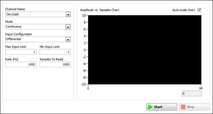
But what settings I need to set in the window of analog input
Thanks for a response
Hi Arbo,
the configuration depends on what type of signal you would expect.
If it will be similar (frequency & amplitude) that generated, then configure the same as AI. One thing you should pay attention to, is to choose an appropriate Terminal configuration (Diff, CSR, NRSE) - you can read about it here: http://www.ni.com/white-paper/3394/en/#toc4
-
SMU-4304 causing the ripple on the input signal?
I have an SMU-1082 chassis that contains a high-6341 and a PXI-4304 module. To check my code, I have connected the analog input (channel 0) of the 4304 to the digital output (PFI 12) of the 6341. My program VI shows a ripple of Vpp 0.2 on the analog input that I'm not using a scope.
The wiring is SMU-6341 [12 PFI, DGND]-> SCB - 68 a,--> TB-4304 [AI0 +, -]-> SMU-4304
I have attached photos of the verses reach the graphical VI. The scope is the AI0 + AI0-terminals and the TB-4304.
Y at - it a supplement on the ground that I should use, or is - this normal for the-4304 to add the ripple?
Thank you
Ron
Short answer, is that there is nothing wrong with what you see.
You have connected a digital output signal low impedance to a digitizer analog high input impedance. Since a digital signal is essentially a square of variable in time wave and square wave have edges of transition that contain information of very high frequency, you will almost always see a form of "ripple" (see animation synthesis of fourier of a signal square from this Wikipedia page ). Thus, a digital output signal is more concerned with the synchronization and the upgrade to be a square wave perfect.
In addition, you can see additional "ripple" because of differences between the SMU-4304 and the noculars that you have demonstrated. the noculars can be a combination of a bandwidth of upper entrance (which can come from various sources like low sampling frequency on the 4304 which would result in a higher frequency of information recorded by the noculars for smoother transitions to research) and, possibly, a lower input impedance (causing less, if any, the reflection of signal which would cause the ringing of the signal).
-
We have a NI USB DAQ to 6341. I want a waveform analog output by external triggers sawtooth. In other words, there will be a sawtooth signal generated each 480 pulse input. The frequency of the trigger is 5 k Hz, therefore, the sawtooth signal generated is around 10 Hz.
But I keep on getting error about tampons codes. This time, the error message is:
Error-201025 occurred at DAQmx start Task.vi:7220001
Possible reasons:
Buffer not timed by the equipment operations are not supported for this device and the Type of channel.
Set the size of greater than 0 buffer, do not set the timing of the sample clock or the Type of sample on request time value.
Task name: _unnamedTask<856>
Source:
DAQmx Start Task.vi:7220001
The task name: _unnamedTask<856>Can someone help me with the related code?
Thank you!
This problem occurs because the DAQmx starting VI is execution of each loop. This restarts the task more before she can finish out the last set of data. In most of the applications you will start the task once and let it go until it's over. Some applications require to start and stop periodically, so you should use the task to stop DAQmx before reusing the VI to start.
I think that there is a fundamentally better way to create your application. If I understand this right, you want a sample of the wave in saw teeth for each pulse of the "external" release trigger. Is this fair? If this is the case then what you really want is to use an external sample on the VI of DAQmx Timing clock. This is similar to how this example is implemented: https://decibel.ni.com/content/docs/DOC-11195
Also, I think what you're trying to do is to repeat the same output samples several times. If this is the case, then you want to use a property node to regenerate the samples. In other words, you just send a signal sawtooth with 480 samples and the DAQ hardware will repeat these samples repeatedly until you stop the task: http://digital.ni.com/public.nsf/allkb/DD750D84BAD703E386256E6E005B41AC
Jeremy P.
-
myDAQ inaccurate reading of the analog signal
Hello
I'm usign the myDAQ in lieu of a USB6341 who is busy on another configuration. The DIF is with the USB6341 I connect two analog inputs without any noise problems, whereas with the myDAQ, I get what you see in the image as an attachment.
Now, (the white line) of a flat line but often I get all these ouliers tips coming clearly through the myDAQ.
Two different voltage on two analog input signals of the my DAQ I can see the same spikes descending in the same moments for both signals, which is another confirmation that the noise is added by the myDAQ.
Also, try different myDAQs (we have many University) does not solve the problem.
Any idea on how to solve this problem?
Thank you very much.
Giacomo
Hello, Giacomo,.
Sorry for the late reply.
Now that you mention the myDAQ DMM.
Please note that the DMM uses a different circuit (Figure 2, page 5):
http://www.NI.com/PDF/manuals/373060e.PDFHow the signal looks like with the myDAQ scope Soft Front Panel?
Although the USB-6341 has different (and better) specifications seems to be rather a noise or signal problem floating.
Can you 100% certainly confirm that you do not see this problem with the USB-6341 when you perform a differential measure?Have you tried the method explained in Figure 7 on page 13?
Do you see a difference when doing this? -
How do I synchronize pxi-6341 analog output to the analog in pxi-4304
I have an SMU-1082 chassis that contains a high-6341 and a PXI-4304 module. I went out a sinusoidal signal of pxi-6341. AO.0 channel for the pxi-4304. Channel ai.0. The pxi-4304 isn't receiving all signals up to about 75 MS later. How can I synchronize synchronization between the 2 modules together to stop this loss of data?
(Finally, I run a waveform digital off the 6341 and in a device while the 4304 captures analog response from the device. "So I'll need to have all sync'd up).
Thank you for your help,
Ron
After trying many "tricks" with various DAQmx screws, I finally found the solution. I simply had to stagger the 'task to start DAQmx' between the entry and exit, as shown in the attached photo.
Hope this helps someone.
-
Model generation with USB-6341?
Hi all
We have developed a software quasi multifunction 'device-independent '. This sw is capable of generating the sequence shot timed with the device really used. Up to now, we have used devices PCI-6025 and USB-6221, but now we bought a USB-6341 and when I try to use a message of 200565 error pops up: "specified digital channel contains more bits supported by the version 8 bits of the Port DAQmxBase write.» Use the version of DAQmxBase Port write who takes in charge the broader digital ports. Minimum size of write in bits: 32 "
I tried to change PORT0, PORT1 and PORT2 but only PORT0 is legal for the model generation process and it requires DAQmxWriteDigitalU32 function...
I don't understand why.a / 6341 contains 24 DIO lines
b / only 8 DIO lines are clocked by materialThen there are 24 DIO lines (i.e. 24-bit 32 no!), but only 8 lines are timed by the hardware and I want to use only this 8 lines for model generation!
Our whole software is based on 8-bit pattern-berries (writeArray type is "uInt8"). If we cannot use this structure, we must rewrite dozens of functions...So, how can we use the function of DAQmxWriteDigitalU8 with USB-6341 or what can we do?
Thank you
-George Cs.-
Dear George,
It is an interesting question, which may seem a bit unintuitive at first. The main reason for the 32-bit write operation (although the USB-6341 has only 24 DIOs) is that the functions and the driver support other devices too. As you can see in the manual of the unit (http://www.ni.com/pdf/manuals/370784d.pdf) X Renault series supports digital IOs up to 32 bidirectional signals.
To keep things consistent exploitation of 32 bits is required even if you use only a subset of the available ports.
I hope that this helps to explain.
Best regards
-
SMU 6341 and SCB-68: problem with several entries... * URGENT *.
Hello
I have an urgent problem, I would really appreciate help with.
I have a terminal block (SCB-68) connected to a multifunction data acquisition (6341). There are 4 entries in the Terminal:
1 sensor laser displacement, coming from a controller as a signal of analog voltage output ("1V" and "0V" on the controller). Connected to AI 0 and GND.
2. The accelerometer (PKI, coming from a then the voltage signal conditioner) connected to GND AI and AI 10.
3 load cells (PKI, coming from a then the voltage signal conditioner) connected to AI 11, 12, 13 and 14, each connected to the GND PIN is close.
Problem:
By MAX, if I read in 6 channels above my data acquisition (6341), my displacement sensor (#1) and the accelerometer (#2) behave very well. However, among the channels (AI 11 and AI 12) load cell switch in tension, as if they follow the movement sensor voltage (#1). For example, there is usually a mV - 800 in AI 11 voltage change.
This problem disappears when I'm not reading travel (HAVE 0, #1) laser. that is as soon as I remove this channel of my task, the readings of cell and accelerometer support back to normal (base voltage ~ 0V). Yet once if I ask again the laser channel, I see a vertical movement in the readings of load cell 2 (displacement varies with the current tension HAVE 0).
Attempts of fixation:
-tried to change the differential using AI laser sensor 0 and AI 9
-tried to delete the field of laser 120V Power
Any ideas at all would be greatly appreciated!
SCB-68:
http://sine.NI.com/NIPs/CDs/view/p/lang/en/NID/1180
SMU-6341:
http://sine.NI.com/NIPs/CDs/view/p/lang/en/NID/207415
This is the general idea. If you must use high impedance sources and that you have enough channels available, placing a channel of the grounding of entry between each other usually helps. You must analyze these chains grounded. Just grounded isn't them enough.
Example: Sensor has = AI0, ground = AI1, sensor B = AI2, ground = AI3, sensor C = AI4, AI5 = ground. Read AI0:5.
Lynn
-
Measure the time of the rising edges of a digital stream using a USB-6341
I have a DAQ USB-6341 map.
I use Measurement Studio (writing code in c#) on a Windows 7 computer.
I'm relatively new to the DAQ cards, programming, so I could ask something that is obvious (sorry if this is the case).
I went out a stream of digital pulses to an analog output channel. I wired this channel to one input of the meter channel. I am able to measure the number of edges upward to the inlet of the meter channel (since the digial flow is continuous, the number of rising edges increases with time).
I would like a time stamp of each rising transition and I like to keep these timestamps in a table without ever growing (or maybe bin these timestamps in a histogram).
Set up the meter channel to provide the timestamp data? (rather than just count)
Thank you for your help.
WRB,
The meter must be able to measure the relative time between the different edges of your signal. To do this, you will take care to set the meter to measure time. It will measure how long a full period of your signal takes. You can configure edge that you want to start with. You'll want to set up your timed 'implied' measure. This sets up the meter to automatically take action whenever a period is over. While it's not exactly a timestamp, you can find the distance between two edges by adding the time periods between the banks in question.
I see another technique that you can use. This would put the counter to edges of County one of the basics of time of your device (it has 100 KHz, 20 MHz and 100 MHz bases long). Then configure the task to use your signal as a sample (configuration to use rising edge) clock. Whenever the song occurs, you will get the number of ticks ticks selected timebase that took place at that time. One thing to note here, however, is that the counters are 32-bit wide, so your code will have to manage the overthrow of this charge if you are using a fast time and base running for long periods of time.
Hope that helps,
Dan
-
Two signals interfering with each other
Hello
I have a problem with a trace of pressure and a vibration sensor. I have a card PCIe - 6341 DAQ. I connect my pressure signal to a channel (say ach0) and I connect the vibration to another analog channel (say ach7).
In labview, I use an assistant DAQ. When I use it to sample only one of the signals, there is no problem. If I add two channels in the configuration dialog box, the signal pressure becomes superimposed vibration signal.
Analog signals entering data show no interference (checked with an oscilloscope). I suspect that what is happening inside the data acquisition card.
Any ideas why this happens?
Thank you
Masoud Mashkournia
Hi Masoud,
It seems that you see 'ghosts' on your channels. The 6341 multiplex via the analog inputs. Therefore, if you are scanning between high voltage and low voltage, especially when you use CSR, you can see ghost images if the signal from the previous channel file completely or have a path to the ground. Here is a good article from the knowledge base that describes ways of eliminating this remanence.
I noticed that you use the configuration of the CSR on your DAQ Configuration Wizard. Try using a differential input configuration. This can help eliminate unwanted common mode voltages. In addition, you can try place a middle way in scanning which is connected to the ground at AIGND in the DAQ command scan. This can help with the mass of the previous signal. Most likely, you will want to scan in this order: pressure, ground, vibrations.
Please let me know if it helps.
Best,
-
Questions of signals (s7 edge LTE - iPhone 7 Plus 4 G/E)
Hey guys,.
I know there are a lot of posts on this topic but I can't really find the one that corresponds to this...
So I moved from s7 Edge for iPhone 7 more. Since the switch, I have signal problems. Where, normally, I LTE 3 bars on my edge of s7, I now get 4g and E even on my iPhone 7 more. What is going on!!! BTW, I'm on T-Mobile.
Thank you
Hey Greggaa,
Thank you for being a part of the communities of Apple Support.
If you get a poor cellular signal where you used to get full LTE signal, then it might be an update available for your iPhone carrier. Please follow the steps in the article to check this update:
Update the settings of your company on your iPhone or iPad
Take care.
-
I have an iPhone 5s (model 1533) and after the update to iOS 10 I can't get a signal, I tried a full restore and update and also reset network as well as the obvious reboot. First, he would get a signal a little while but if I tried to make a call, it would go directly to no signal, it also seems to have the power of the weak wifi signal too, related? Must say that I had a lot of problems with my apple stuff recently, at the end of my home! All ideas welcome please?
I had the same problem on Verizon. I fixed mine by going to settings, cell and disable roaming data and then on again. Its happened twice so far, as well as a few other bugs. iOS 10 is probably the worst launch of iOS.
Maybe you are looking for
-
Necessary German spelling checker
I would get a German spelling checker in Firefox (similar to the way in which it exists for Thunderbird). This spelling checker can be installed in Firefox 4?
-
Why when I open the other Web site I don't see photo
the website asialadyintroductions.com when I open it, I don't see the pictures of me and my friends colleagues... Why URL of affected sites http://www.asialadyintroductions.com
-
Question about backup of the partition on the Qosmio G20
Hi everyone, I was wondering is it possible to get the backup of your hard drive or the partition on qosmio g20? I tried the real picture, and ghost, but they could not get access to the qosmio scsi disks, when I ve checked toshibas recovery dvd I sa
-
HP DV7 - 1247CL: I was stupid and broken my RAM housing... where can I find the part to fix it?
Can someone tell me where I can buy a replacement for my RAM box? I finally decided to go on my poles 2x2gb for 2 x 4 GB sticks, but it was late, I was tired and I broke accidentally one of the arms of the RAM box because I was stupid. So now, the RA
-
Access Internet via WiFi with E3200
Hello is it possible the E3200 router to connect to internet via wifi (WLAN) interface? In fact I can use the ethernet port called 'Internet' to connect with my router Fritz Box (which is responsible for my internet connection to my DSL provider). Bu