generate waveforms
Hi all
How can you generate waveforms with time and amplitude? where you mention amplitude step size and grandeur of no time.
Thank you
This strangely similar to work at home.
You try to build a specific type like a sine or triangle wave?
Where are you stuck?
I recommend you watch the LabVIEW tutorials online
LabVIEW Introduction course - 3 hours
LabVIEW Introduction course - 6 hours
Tags: NI Software
Similar Questions
-
generate the output waveform on 6259
Hello
I would like to generate signals of "simple" digital square output 3 6259 NI Board of Directors of 80 Hz.
Because of the wiring of my test tool driven 6259 Board, I can't use the output of the meter, but I need to plug into 3 output lines.
I re-used an existing vi and made by a subcontractor, but the generated waveform on my DUT does not have the expected frequencies (although it seems OK on the generated graph). Indeed, there are some forms of square waves, but not continuously. A sort of "pomade" and "elected" frequency does not match the measured frequency. If someone has an idea to help me, I have not experience on labview yet!
Thank you!
You have 4 unique digital States aimed at bike. Each cycle produces 1 full period of each of your square waves. If you want the output to 80 Hz, you must set the sample to run 4 * 80 = 320 Hz clock.
The other thing you see on the scope is that there are short bursts of pulses with parent long time between bursts. The calendar during the bursts are what control tasks. The time between bursts is caused by using the button "run continuously. Also that according to them, you complete vi almost immediately rather than waiting until they run awhile. Put an end to the execution of vi initiates self-cleaning of LabVIEW. These things represent the time brief burst and the ISH between bursts.
-Kevin P
-
delay between the identical waveforms generated
Hello world. I want to generate tension by the use of the NI USB - 6353 X. When I tried to use the vi 'Voltage - finished output.vi' example, I realized that there is a period of time between two generated waveforms. It is an undesirable situation for our application. Why is this delay happens? How to generate at the same time?
VI of function generator based on there is an entry called Signal of Reset. Than the true value. What is happening is that your second wave comes to be a continuation of the first. As the first waveform settings say he needs a little more time, you get this time dead at the beginning of your second waveform.
-
Generate digital waveforms of high frequency
Hi all
I have some problems. Today, I am generating several digital high frequency waves with my DAQ (PCI-6251) card. The duty cycle of the waveform must be adjustable.
The required frequency is 100 kHz.
To do this, I have tried several solutions:
(1) I used counters in the acquisition of data to generate waveforms, and it worked fine. However, I have only two counters. In my application, I need to at least three waveforms with different cyclical report;
(2) I used a 'loop' and structures 'case' in labview to build the model of waveform and then feed them to the digital I/o. However, the problem with this solution is that the frequency of the wave generated cannot be high.
(3) I used a 'digital' generator in Labview to generate waveforms and then feed them to the digital I/o. In this case, the time base is from an external source (200 kHz). However, with this solution, the cycle is not adjustable.
Please give me some advice on how to make these waveforms. Your assistance is appreciated.
OK, so I may be wrong, but after mucking around for a bit, I realized that the regeneration should be automatic - in other words, if you a pattern to the right and then just leave your VI work in a while loop, you will find that the generation is continuous. Discover the correlation dig write metered in the finder for example Labview. You can leverage this as you get the cyclical report you are looking for. You can split the signal down what you write a single period consisting of a series of 0 and 1. In other words, if you want a wave of 100 kHz with a cycle of 20%, you write a pattern of digital waveforms a 1100000000 at the rate of 1 MHz. Using this technique, the resolution of the cycle will be limited by the on-board clock speed (80 MHz = 0.125%).
Let me know if this makes sense - I am unable to reproduce this on my desktop and have never had to do this before.
Cheers, Matt
-
niHSDIO dynamic generation and Acquisition using LV configure Trigger VI
Hello!
My experience is limited within the environment of digital programming; Nevertheless, I have worked on this problem for a few days and would appreciate some comments if possible.
I am trying simply to generate and acquire a duty cycle of 50% of 8 MHz TTL pulse train on a PIN DIO of the PCI-6541 and acquire back from the signal on another axis of DIO. I have a connector corresponding to the embedded 6541 VHDCI connector which of course the generation and acquisition DIO welded pins to provide a loopback effect.
In short, I use the niHSDIO configure Trigger VI (instance--> start Trig: SW), niHSDIO send software Edge Trigger VI and write Named Waveform VI (instance--> data: 1 D U32) in the generation section. For the section of the acquisition, in short, I use the VI of waveform Fetch niHSDIO (instance--> single record: WDT).
I see results in the waveform acquired showing the generated and acquired digital TTL pulse on the respective DIO pins train, but I can't seem to get my 8 MHz frequency requirement. In addition, the lower part of the assignment of pin DIO, more frequency. Unfortunately, due to the configuration system required, I have confined myself to pin 12 DIO for the generation of digital pulses. Even with a 50 MHz clock frequency, I'm ~ 6 kHz of frequency acquired max. I looked at changing the parameters of the wave form VI named write, but it is not possible because the VI call a library function node. I also tried to generate a waveform of 8 MHz through a VI of generator of digital model, but I do not believe, you can trigger on generated waveforms? It seems that you must generate data using a simple loop to as a counter and sending the result to the waveform VI named write. Are there other ways I can simply generate and acquire a digital signal of TTL of 8 MHz (no external connection)?
In any case, any kind of feedback would be greatly appreciated.
Thanks in advance for your time.
Dan
Dan,
Sorry about the nomenclature. I usually use 0 x or 0 b for indication of radix, it is not necessarily a kind of standard, just what I used in my old days of the Assembly.
Looks like you have a knowledge about the data. Basically the material is just save in DRAM an array of words of 32 bits, with each bit corresponds to a data channel and each element being generated to the sampling clock rate you enter to your vi. Everything else is just easy data manipulation or usage. The interleaving method is just as I like to create a toggle model. You can easily do a loop with an inverter and feedback node or use on the construction in screws to signal generation. In addition, you can use the software digital waveform editor or control panel test to generate the county or toggle modes.
Give us an update when you enter the laboratory and let us know if you encounter any other disorder.
-
FPGA wave sinusoidal generation discontinuity
Hi all
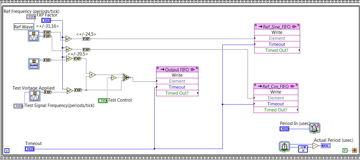
I have a question about the generation of sinusoidal waveform FPGA: the generated waveform has unknown non-periodic discontinuity. I want to know where it was generated and how to solve it.
As you can see on my FPGA code below, I generated reference signal - a wave of fishing and a cos wave by using the function of 'generation of the sine wave. Then I write the data to their corresponding FIFO and the sampling rate is controlled by "Period In (usec)" and it is set at 20. Thus, the sampling rate is 50KS/s.
Fig. 1. Code generation of FPGA sin wave
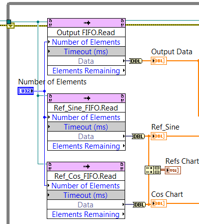
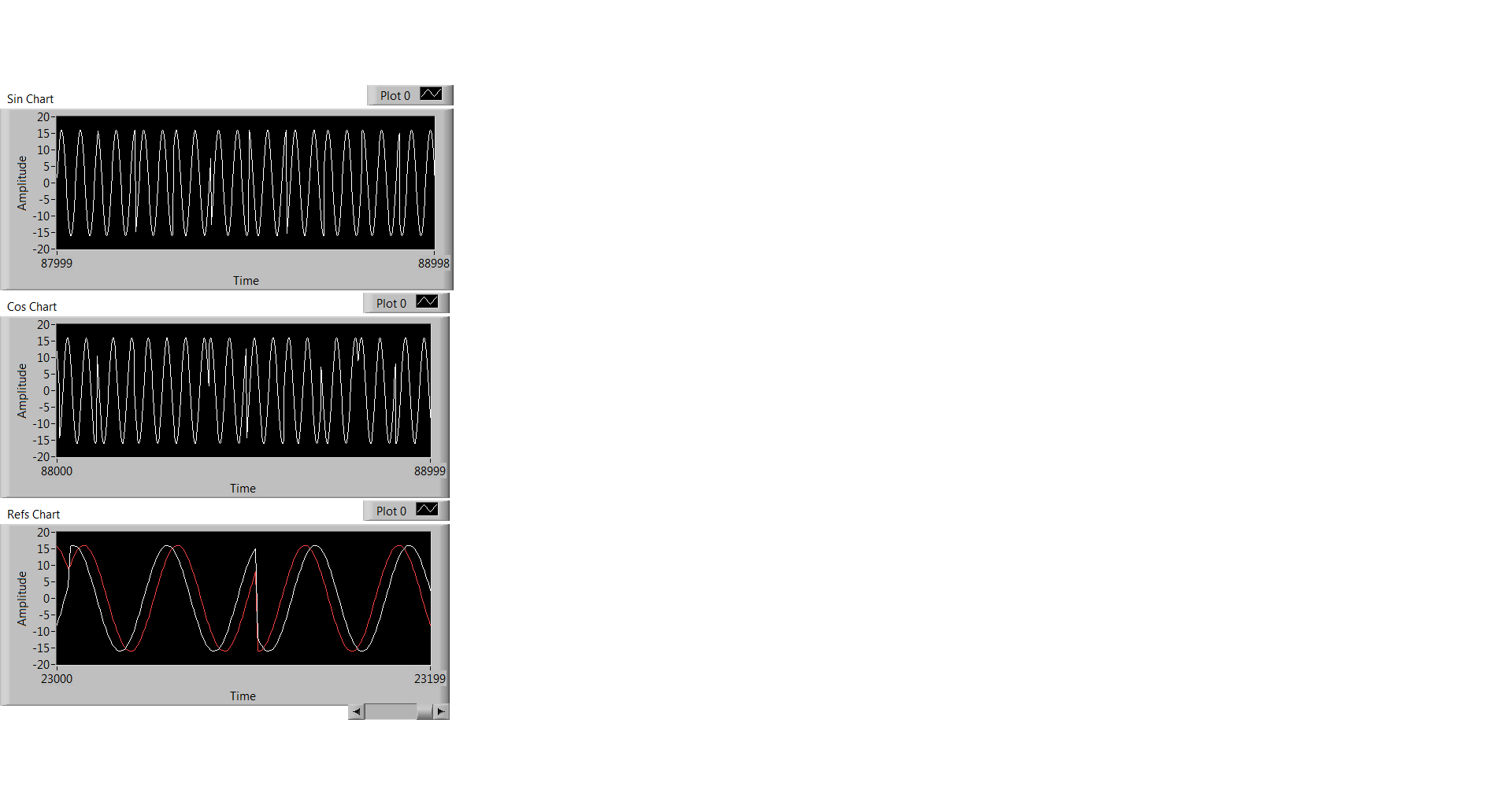
At the level of the RT, I observe the data through the code illustrated in Fig. 2, and what I observe is Fig. 3. Three graphics from top to bottem are: result of the sine, cosine wave result, sin / cos wave shown using the same chart.
Fig. 2 RT level Code
Fig. 3 Sin / Cos waves are the result
Everyone has the same problem ever or any input on what has caused this?
Thank you!
Kind regards
Doris
Hello
Thanks for responding! I think I solved this problem. What's happened is that the execution time for the rest of my code of RT level is longer than the duration for the FIFO to be filled, so the code FPGA that writes data in the FIFO to wait to get code RT to finish. FIFO data are not time continues because of this reason.
Kind regards
Doris
-
Multi-multifunction-Synch rate HAVE AO
Hi all
I'm new to Labview and these tips.
I work through the AI Multi-multifunction-Synch-AO example as found for example NI Finder and I was wondering what difference between it the "rate of generation of update" output "Sample clock" and the sampling rate is on in the "sample information" of the "core generator.
My first thought was that first of all, a control material and a second control of the software, but I find that when the two are adjusted against each other, my changes of sinusoidal frequency, even when the frequency parameter is left unchanged.
Thanks in advance.
Hi currentenglish,
Generation of update rate attached to the "sample clock" indicates the rate at which the jury will clock samples.
The "sample information" is used by the software to generate a waveform appropriate considering the rate of the material. If there is an incompatibility between these two values, you will have a different frequency than you expected. For example, if you generate the waveform into thinking that the sample clock is 1 kHz, but it's really only 500 Hz, the generated waveform will be half the frequency you specify.
You should connect the rate of generation of update in the sampling information to ensure that they are always the same. I'm actually a little surprised that this example of shipping is already this.
Best regards
-
BUG? Out of multi channel analog Flips which channel it sends
I a program that channels acquires 4 analog inputs, 2 analog output channels to send and acquires 2 input channels of the counter (on a separate card)
My problem is that the analog output flips which channel it outputs. I built a table and my waveform desired ao0 at the top of the table build entry, then I drag the table of construction down to make entry as a second entry and I plug my second wave this entry. I noticed strange things on the scope. The program worked correctly, but repeatbly.
The analog output channels the following steps
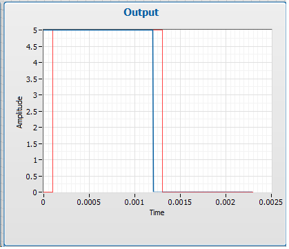
channel 0 is sent to a level of zero, then for 1 data point a level 5. It comes to trigger a signal generator to the output of a wave of fishing 1 Hz, 1Vpp, 2cyc
1 channel is sent with a square wave to trigger a camera to take a picture for each pulse.
Step 1: Open SLOSHTABLEV4.vi
Step 2: run.
Note: the channel impulse is sent the trigger generator waveform causing the waveform to generate each pulse
the trigger channel ends as high. to 5 volts.
Step 3: Run simpleao.vi and set both channels to zeroStep 4: See Re running SLOSHTABLEV4.vi that flips out what channel it is sent!
There are three forms of production,
the right one
one where the waveform relaxation is camerapulse
one where the waveform trigger is activated from the beginning.The solution was to update the drivers. Ugh!
-
Hello, everyone!
I m using USB 6251 OEM for more than two years without major problems, but my applications are increasingly complex and OR start offering NI USB 6353, with many improvements, mainly on the transfer speed.
My problem is: using 6251 I run an application that generates analog data with 100KS/channel (2 channels) and generates a digital stream data with 1MHz, 8 bits wide. Both tasks are Nsamples mode, without regeneration and can´t stop or loose data while running. It works really fine on 6251. On labview, just changing the necessary (using Daq Assisant to replace tasks) to use 6353 an error message appear on screen:
"Overflow memory on-board unit. Due to the limitations of system and/or the bandwidth of the bus, the driver could not write data to the device fast enough to track the rate of output of the device. Reduce your sampling rate, or reduce the number of programs that your computer runs at the same time. »
If 6353 is faster than 6251 why this error just on 6353? 6353 is worse than 6251 inthis?
Cristiano
Hi André,.
I m waiting for a work around to fix this bug. In my application, I use this way to generate waveforms for more control. The application control how many cycles is generated on each stage, based on digital input, digital output stream is also controlled. In this way is really important have these two tasks running at the same time. We have the same tasks on 6251 and we decided to migrate to 6353 because it has more channels and improvements on communication.
Thanks for everything and I m waiting for a report to correct this bug.
Cristiano
-
variable phase shift between two analog output signals
Hey! I would drive two different piezo elements with an sine - / square signals and have a phase shifted output signals. After some trail and error, I was able to get a second analog output on my card PCI-6221 (using LabView 8.2) also allowed me to have different amplitudes for both signals. However, I could not output signal having a frequency different and most importantly to my request to have one of the signals variably shifted phase.
Thanks for the very useful suggestion. I have attached the file .vi installation I've run so far.
Hello!
A way to generate waveforms is using the analog waveform Toolbox. I created an example VI that is attached and that shows you a way to use the base generating function VI. I saved for LabVIEW 8.2.
I hope this helps!
-
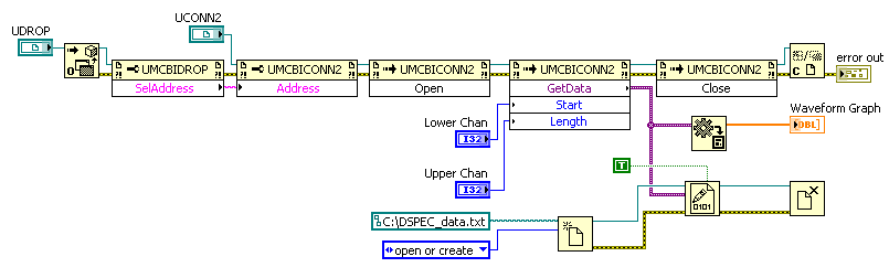
I want to save data in a binary file. This VI takes into account several channels and displays them in a bar chart. The generated waveform out with precision, but the generated text file does not save the data. It's only a few characters long, and I don't seem to be able to interpret it at all. I tried to save the data of type variant and the data after the conversion (before it is in graphic form). The files and the VI are attached below. Any advice on where I'm wrong would be greatly appreciated.
Shultz,
Do you intend to write a binary file (more effective, unreadable by humans) or (less effective, human-readable) text file? They are of two different file types.
The code in your screenshot opens a text file but then saves the binary data of the Variant. These data are likely not as ASCII (text) format so when you try to play you see what appears to be garbage (really, what happens is that your text editor's interpretation of the 1 and 0 of binary data of type variant as ASCII coding).
If the chart appears correctly, then I think that the GetData UMCBICONN2 returns an array of numbers. In this case, you want to convert this table of numbers to strings, and then use writing text VI of file to save to disk as follows:
Sorry for the screenshot - I would normally post an excerpt or at least fix the VI but I work on a development machine that does not have a version of LabVIEW on it and you don't would not be able to open any VI I saved.
I hope this helps. Best regards, Simon
-
DAQ product with +/-analog output 12V?
We are looking to update a manual test area.
We are looking for a product DAQ with analog outputs capable of +/-12V
We are not generating waveforms. Just using LabVIEW to a tension he set in the range of - 12V and + 12V.
OR anything with this ability he selling?
I found the NI PCI-6703 and would serve our needs except that it is +/-10V.
Good morning New York,
Consider the SMU-4322 or NI 9269. The SMU-4322 supports + / 16V by channel. The NI 9269 has 4 (+/-10V) channels that can be cascaded for isolated older tensions.
Kind regards
Izzy O.
Product Support Engineer
NI.com/support
-
I am actully trying to create a time delay in a signal and then later I want to apply an algorithm to find TDOA between signals from a single signal source. They have a relative phase shift and tried to model a VI so that I can see the signals visually and analyze TDOA analytically first, and then ensuring the proper functioning of the Algo.Currently I am unable to differentiate visually signals having different phase on the only indicator. I see that a single waveform. I want to see both...
Hi defined
Right-click your plot of annexed table and go to the tab 'Balance '. At the bottom of the "Balance" tab, make sure the 'ignore wave timestamp x - axis' is not checked. The parameter t0 on function 'Building the waveform' is a timestamp data type. If this box «ignore...» "is checked, the chart uses the indices of values Y, which always start at zero.
Note that the generated waveform will have a number of samples and that change the original horodotage moving all samples.
Let me know if you have any other questions!
-
file lvm recorded with time stamp graphic display
Hello
I have headaches display my data with correct timestamp. There are so many methods to save the data. Here, I decided to save it in a text delimited as lvm. a screenshot of my vi segment is attached. I want to use this way rather than other methods is the flexibility it offers. I'll be able to add more data to store that I develop the vi. (So I'm storing data of the DAQ assistant and my calculated values.) I've attached a screenshot of the file I also read.
I would use another vi to open this file and it draw a chart/graph to show a trend of the acquired data. Can someone pls Advisor mid on which is a better way for mi to do?
Thank you very much!
POH
Hi Malou,
Sorry for the late reply, I was rushing to complete my project, has not been able to answer.
Yes, I managed to solve it. In any case, I've used this high rate in the acquisition of data wizard is to allow the acquisition of continuous mode & use a software filter instead of filter material. However writes to the folder this way - write string in .lvm, max is 10 samples/s unless I have use tdm (I'll then everything in the newspaper).
I was not able to display the correct timestamp was due to the fact that I have does not add to the timestamp of the start time for the timestamp in waveform display. I won't be able to go down to my lab, & my machine have no LabVIEW, so what I do is to extract some parts of my report to share.
For the part that I used to display the graph (can be seen on the attachment), I deleted the 1st column, which is the time stamp (for display of the spreadsheet), but extract the 1st element - convert timestamp DBL it when I start recording in the DAQ vi (written with the header).
This excerpt (which could be considered as a group of numbers in the file lvm) and converted to the type timestamp and wired for generating waveform block, providing the start time of the wave.
Then I replace the use of the chart with graphic, graphic is suitable for data acquired and graphic tracing is better for the time of execution of the data display. now it seems to work fine for me, except for the load time may take some time for larger files.
Thank you for your participation in this thread!
See you soon!
POH
-
Hello
I know is he already written VI to generate a double 33220A pulse which we can control 1 and 2 pulse time and the time between the 2 impulses?
Thanks for your advice in advance.
Use generate waveforms arbitrary comes with his instrument driver, http://sine.ni.com/apps/utf8/niid_web_display.model_page?p_model_id=104, write a table of data point replect your two impulses.

Maybe you are looking for
-
OfficeJet 6500 Wireless: paper jam to halfway through the process of copying
try to do a copy and paper jams to halfway through the process, and the custom of move. I believe that the error message reads: error in the printer (0 x 61011 beb) im not sure if this is what reads the lettering is hard to read while scrolling by on
-
I just got a call from a gentleman who said he was with the support of Startech and they had received a report of error on my computer (which is possible). He asked me to allow him to log on to my computer. Anyone know if it's legitimate?
-
Why my laptop isn't load... in fact, why isn't same regestering the Ruddy thing is pluged?
It's a srs Dell and I had six months give or take. Today all a süden is not load or record as well as the dam thing is pluged. What should I do? Any help would be welcome.
-
I have 2 problems first no sound and then my cd/dvd drive has stopped working Rather than simply erase the audio driver I erased everything (even hidden) in my sound, video & game in the Device Manager controller. The windows driver try to give me i
-
HP Officejet 6700 Premium: Officejet 6700 premium prints in color but not black
Hello, I had this printer new and used for 6 months, worked perfectly. We moved and he was sitting in the box for the last 16 months. I have just connected printer to the top and she supposed to replace the black print cartridge, so I did. He also